Dual Rate setting
Up to 6 dual rates can be set for each condition. *D/R (Dual Rate) is set for each condition, and is not reflected at other conditions. *D/R (Dual Rate) at the top of the D/R list has priority.
Setting method
- Touch the [D/R] button from the AFR (D/R) screen of the function (ailerons, elevators, etc.) whose dual rate you want to set. The D/R list screen shown below is displayed. Touch the (function) button of the dual rate number to be assigned. That rate is automatically assigned to that function.
- Next, select the switch and its ON/OFF directions.
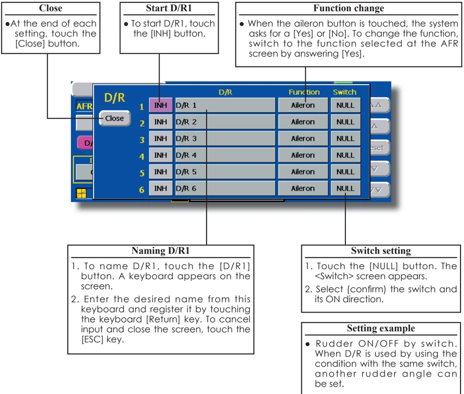
Close
- At the end of each setting, touch the [Close] button.
Start D/R1
- To start D/R1, touch the [INH] button.
Function change
- When the aileron button is touched, the system asks for a [Yes] or [No]. To change the function, switch to the function selected at the AFR screen by answering [Yes].
Naming D/R1
- To name D/R1, touch the [D/R1] button. A keyboard appears on the screen.
- Enter the desired name from this keyboard and register it by touching the keyboard [Return] key. To cancel input and close the screen, touch the [ESC] key.
Switch setting
- Touch the [NULL] button. The <Switch> screen appears.
- Select (confirm) the switch and its ON direction.
Setting example
- Rudder ON/OFF by switch. When D/R is used by using the condition with the same switch, another rudder angle can be set.
76 <Model Menu (Common Functions)>
Prog. Mixes
Program mixing which can be freely customized. Up to 10 mixings can be used for each condition. [All model types]
Programmable mixing may be used to correct undesired tendencies of the aircraft, and it may also be used for unusual control configurations. Mixing means that the motion of a command channel, called the "master," is added to the motion of the mixed channel, called "slave."
You may choose to have the Masters trim added to the Slave channel response, if you desire ("Trim" setting). The mixing curve can be changed so that the undesired tendencies can be corrected effectively by setting the LINEAR1/LINEAR2/EXP1/EXP2/VTR/LINE/SPLINE modes. The Delay function can be programmed for each rate. The Delay is used to change the rate smoothly when switching. You may define Mixing ON/OFF switch, control or you may choose to have mixing remaining on all the time.
Offset-type mixing applies a fixed offset or preset to the programmed channel servo operation and may control up to four circuits simultaneously. The Programmable mixing includes a powerful link function, which allows Programmable mixing to be linked with the special mixing functions, or with other programmable mixing functions. The link function can be set up for Master and Slave channel individually.
The slave channel AFR mode (STK-STK mode) may be selected, where the slave channel AFR and D/R settings are observed when Link function is set. The knob for fine tuning can be set up for every mixing circuit. (Fine tune function)
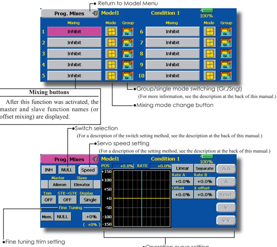
- Touch the [Prog. Mixes] button in the Model Menu to call the setup screen shown below.
• Return to Model Menu
Mixing buttons After this function was activated, the master and slave function names (or offset mixing) are displayed.
•Group/single mode switching (Gr./$ngl) (For more information, see the description at the back of this manual.)
•Mixing mode change button
•Switch selection (For a description of the switch setting method, see the description at the back of this manual.)
•Servo speed setting (For a description of the setting method, see the description at the back of this manual.)
•Fine tuning trim setting (For a description of the setting method, see the description at the back of this manual.)
•Operation curve setting (For a description of the curve setting method, see the description at the back of this manual.)
<Model Menu (Common Functions)> 77
Setting methods
●Group/single mode selection
Activating functions for only the selected conditions:
- Touch the Group button and switch to the $ngl mode. *Each time the button is touched, it toggles between the Gr. and $ngl modes.
●Mixing mode selection
Using the offset mode:
- Touch the Mode button and switch to the Offset mode. *Each time the button is touched, it toggles between the Mix and Offset modes.
●Mixing setup screen selection
- Touch the button of the mixing you want to set. The mixing setup screen is displayed. Activate the function.
- Activate the function by touching the [INH] button. *Each time this button is touched, it toggles between [INH] and [ON/OFF].
●Mixing ON/OFF switch setting and ON/OFF direction switching
*An ON/OFF switch is not set even when the function is activated.
- When you want to turn mixing ON/OFF by switch, touch the [NULL] button to call the <Switch> screen and then select the switch and its ON direction. *For a description of the selection method, see [Switch Setting Method] at the back of this manual.
●Master channel setting (except offset type mixing)
- Touch the Master button to call the Function menu and select the master channel.
- To link this mixing with other mixing, touch the button at the left of the master channel and select link. *Each time the button is touched, it toggles between mixing direction + and - and "No display" (no link). *Master channel control can be set to stick, VR, and other simple travels which do not include ATV, AFR, D/R, mixing setting, etc. In this case, display the <Switch> screen by touching the [H/W] button and then select master channel side control.
●Slave channel setting
- Touch the Slave button to call the Function menu and select the slave channel.
- To link this mixing with other mixing, touch the button at the right-hand side of the slave channel and select link. *Each time the button is pressed, it toggles between mixing direction + and - and "No display" (no link).
●Trim mode ON/OFF setting
- To turn the trim mode ON/OFF, touch the Trim button on the screen. *When mixing includes master side trim, set the Trim button to [ON]. When mixing does not include master side trim, set the Trim button to [OFF]. *Each time this button is pressed, it toggles between [ON] and [OFF]. *This is effective when the master channel is set by Function.
●Slave channel AFR mode (STK→STK)
- When Link is set at the slave side, and you want to add AFR (D/R) to the mixing rate, select [ON]. When you do not want to add AFR (D/R) to the mixing rate, select [OFF]. *Each time this button is pressed, it toggles between [ON] and [OFF]. *This is effective when making corrections when the fuselage is the same but the rudder angles are substantially different.
●Mixing curve type selection
- Touch the curve type selection button of the curve type you want to use to display the selection screen and then select the curve you want to use. *For a description of the curve setting method, see the description at the back of this manual.
●Fine tuning trim setting
- When using the curve fine tuning function, touch the [NULL] button of the Fine Tuning item to call the <Switch> screen and then select the lever, VR, etc. you want to use. *For a description of the fine tuning trim setting method, see the description at the back of this manual.
●Servo speed setting
- When setting the servo speed, touch the Speed button. The Servo Speed setup screen is displayed. *For a description of the servo speed setting method, see the description at the back of this manual. *Offset mixing changes the speed. Use the Speed In and Speed Out buttons to readjust the speed.. The mixing switch can set a delay with a different rate at starting and stopping. *This function is inactive when a mixing switch is not set.
78 <Model Menu (Common Functions)>
Fuel Mixture
Dedicated mixing used in needle adjustment of engines which use a fuel mixture control carburetor. [Airplane, helicopter]
This function is dedicated mixing used in needle adjustment of an engine that uses a fuel mixture control carburetor.
*The needle channel is assigned to CH9 as a default.
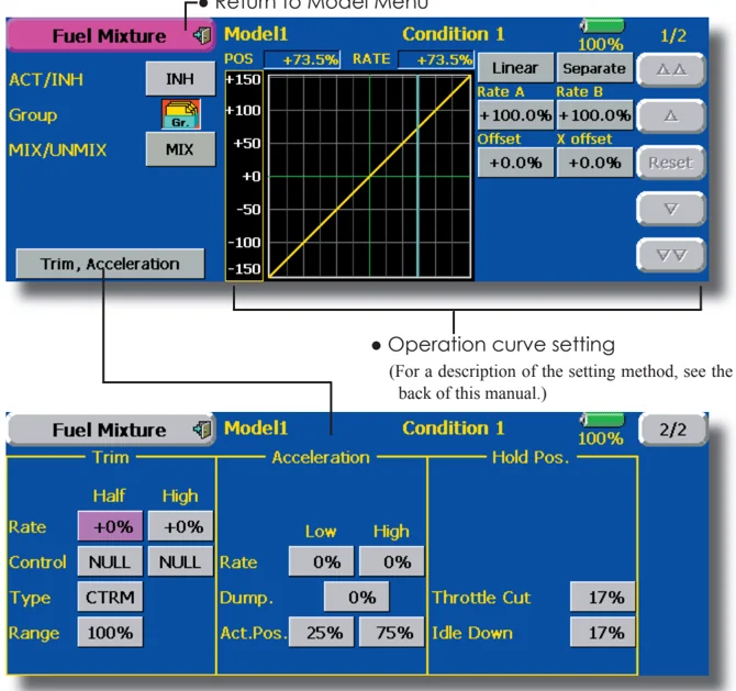
• Touch the [Fuel Mixture] button in the Model Menu to call the setup screen shown below.
Setting method
CTRM mode: Maximum amount of change near center by center trim operation. When the adjustment range (Range) value is made small, trim is active only near the center.
NORM mode: Normal trim (parallel movement trim) operation. When the adjustment range (Range) value is made small, trim is active only near the center. Needle high trim works as high trim based on the center. This operation is similar to reverse ATL trim.
-
An acceleration function can be set. This function is used when there are symptoms of the mixture being either too rich or too lean, which would be generated by sudden operation of the throttle stick. An acceleration (ACLR) function and deceleration (DCLR) function, which temporarily increase and decrease the fuel supply at acceleration and deceleration, can be set.
-
The return time after operation (Dump) can be set for both setting at acceleration (High) and setting at deceleration (Low).
-
A needle throttle cut function can be set.
-
Operation linked with the throttle hold functions (Cut and Idle), Throttle Cut function, and Idle Down function is possible.
-
The needle side cut position can be set. Set it to the fuel side full open position.
When the MIX mode is selected, the throttle curve set data becomes the mixing master. In the UNMIX mode, the throttle stick position becomes the mixing master.
<Model Menu (Common Functions)> 79
MODEL MENU (AIRPLANE/GLIDER FUNCTIONS)
The dedicated mixings, etc. usable when airplane, glider, or EP glider model type is selected are displayed in this Model Menu functions section. First use the Model Type function of the Linkage Menu to preset the model type, wing type, and tail type matched to the fuselage used. Later setting resets the data set by mixing function, etc.
These dedicated mixings can be set for each flight condition, as required. When you want to use the system by switching the settings for each condition by switch or stick position, use the Condition Select function to add flight conditions. (Up to 8 conditions can be used)
Note: The T14MZ is designed so that the airplane and glider (including EP glider) model types can handle fuselages of the same wing type.
The functions common to airplanes and gliders, except some dedicated functions, are summarized without regard to the model type.
The setting items are different, depending on the number of servos, etc. according to the wing type used. However, reread them. The setup screens in the instruction manual are typical examples.
- Touch the Model Menu button of the Home screen to call this Model Menu.
- When the button of the function you want to set is touched, a setup screen appears.
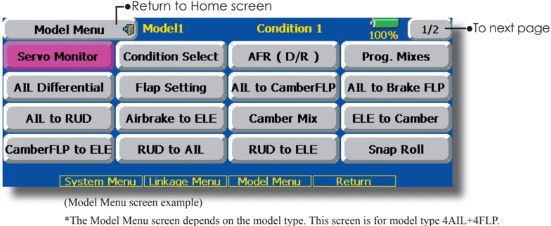
(Model Menu screen example) *The Model Menu screen depends on the model type. This screen is for model type 4AIL+4FLP.
Model Menu functions list
●AIL Differential This function adjusts the left and right ailerons. Roll axis correction and fine tuning with a VR are also possible. This is convenient when making settings during flight. [Airplane/glider, 2 ailerons or more]
●Flap Setting The flaps can be adjusted independently. For a 4 flaps model, the camber flaps can be mixed with the brake flaps. [Airplane/glider, 2 flaps or more]
●AIL to Camber FLP This mixing operates the camber flaps in the aileron mode. It improves the operation characteristic of the roll axis. [Airplane/glider, 2 ailerons + 2 flaps or more]
●AIL to Brake FLP This mixing operates the brake flaps in the aileron mode. It improves the operation characteristic of the roll axis. [Airplane/glider, 4 flaps or more]
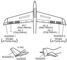
●AIL to RUD This mixing is used when you want to operate the rudder at aileron operation. Banking at a shallow bank angle is possible. [Airplane/glider, 2 ailerons + 2 flaps or more]
●Airbrake to ELE This mixing is used to correct operation of the airbrakes (spoilers) when landing. [Airplane/ glider, general]
●RUD to AIL This mixing is used to correct roll maneuvers, knife edge, etc. of stunt planes. [Airplane/glider, general]
80 <Model Menu (Airplane/Glider Functions)>
•Camber Mix This mixing adjusts the camber and corrects the elevators. [Airplane/glider, 2 ailerons or more]
•ELE to Camber This mixing is used when you want to the mix camber flaps with elevator operation. Lifting force can be increased at elevators up. [Airplane/glider, 2 ailerons or more]
•Camber FLP to ELE This mixing is used to correct for attitude changes when the camber flaps are being used. [Airplane/ glider, 2 ailerons + 1 flap or more]
•Butterfly (Crow) This function is used when powerful brake operation is necessary. [Glider, 2 ailerons or more]
•Trim Mix 1/2 The ailerons, elevators, and flaps trim offset rate can be called by switch or condition selection. [Glider, 2 ailerons or more]
•Airbrake This function is used when airbrakes are necessary when landing or when diving, etc. during flight. (Airplane, general)
•Gyro This is dedicated mixing when a GYA Series gyro is used. [Airplane/glider, general]
•V-tail This function adjusts the elevators and rudder of V-tail models. [Airplane/glider, V-tail specifications]
•Ailelevator This function adjusts the elevators and ailerons of models with elevator specifications. [Airplane/ glider, elevator specifications]
•Winglet This function adjusts the left and right rudders of winglet models. [Airplane/glider, winglet specifications]
•Motor The operation speed when the motor of F5B and other EP gliders is started by switch can be set. [EP glider, general]
•RUD to ELE This function is used to correct roll maneuvers, knife edge, etc. of stunt planes. [Airplane, general]
•Snap roll This function selects the snap roll switch and adjusts the steering angle of each rudder. Servo speed can also be adjusted. [Airplane general]
•Multi Engine This function adjusts the throttles independently when using a multi engine model. (Maximum 4 engines) [Airplane, general]
 AIR BRAKE
RUDDER 1
Winglet
(at Flying wing)
AIL 3
(Chip Aileron)
AIL1
(Main Aileron)
FLP 1
(Camber Flap)
FLP 3
(Brake Flap)
FLP 4
(Brake Flap)
AIL 2
(Main Aileron)
FLP 2
(Camber Flap)
AIL 4
(Chip Aileron)
RUDDER 2
Winglet
(at Flying wing)
V-TAIL ELEVATOR (RUDDER 2) RUDDER (ELEVATOR 2)
AILEVATOR ELEVATOR (AILERON 5) ELEVATOR 2 (AILERON 6)
<Model Menu (Airplane/Glider Functions)> 81
AIL Differential [Airplane/glider, 2 ailerons or more]
The left and right ailerons differential can be adjusted independently. The differential rate can also be adjusted according to the flying state by setting a fine tuning VR.
•A fine tuning curve can be set. Note: Aileron up/down setting (%) reset is +100% when reset when setting is +, and -100% when reset when setting is -. Left and right mixing causes + and - to change. Before flying, confirm the direction of operation.
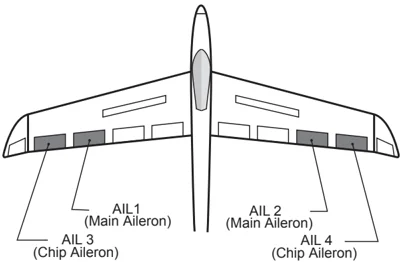
• Touch the [AIL Differential] button in the Model Menu to call the setup screen shown below.
<Wing type: 4 ailerons screen>
*The display screen is an example. The actual screen depends on the Model Type.
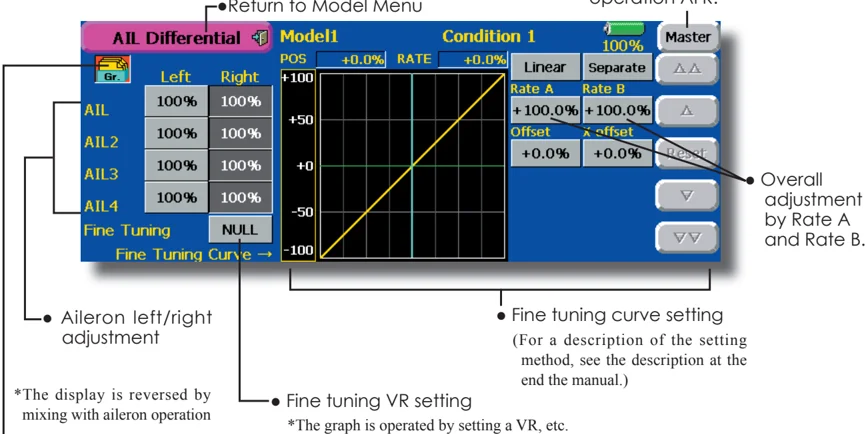
• Return to Model Menu • Calls the AFR screen directly when adjusting aileron operation AFR. • Aileron left/right adjustment *The display is reversed by mixing with aileron operation • Group/single mode switching (Gr./Sngl) (For more information, refer to the description at the back of this manual.) • Fine tuning VR setting *The graph is operated by setting a VR, etc. • Fine tuning curve setting (For a description of the setting method, see the description at the end the manual.) • Overall adjustment by Rate A and Rate B.
Setting method
• Touch the aileron (AIL) 1~4 left (or right) button, and adjust the aileron angles when the stick is moved to the left (or right) end. *The aileron AFR screen can be directly called from the AIL Differential setup screen. ([Master] button) • When setting the fine tuning VR, touch the "NULL" button to call the <Switch> screen, and then select the fine tuning VR. • The fine tuning rate can be set by curve.
82 <Model Menu (Airplane/Glider Functions)>
Flap setting [Corresponding model type]: Airplane/glider, 2 flaps or more
The up/down travel of each flap (camber flaps: FLP1/2, brake flaps: FLP3/4) can be adjusted independently at each servo according to the wing type.
• The operation reference point of each flap can be offset
The camber flaps of a 4-flap model can be mixed with the brake flaps. (Brake FLP to camber FLP)
• An ON/OFF switch can be set.
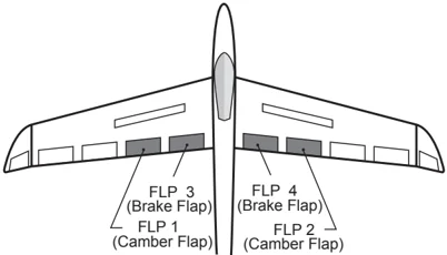
FLP 3 (Brake Flap) FLP 1 (Camber Flap) FLP 4 (Brake Flap) FLP 2 (Camber Flap)
• Touch the [Flap Setting] button in the Model Menu to call the setup screen shown below.
<Wing type: 4 flaps screen>
*The display screen is an example. The actual screen depends on the model type.
• Return to Model Menu
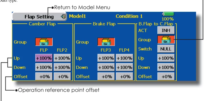
Group/single mode switching (Gr./Sngl) (For more information, see the description at the back of this manual.)
• Operation reference point offset • Up side/Down side adjustment
Setting method
• Touch the flap (FLP) 1~4 Up or Down button according to the wing type and adjust the travel independently.
• To offset the operation reference point of each flap, touch the corresponding Offset button. Use the adjustment buttons displayed on the screen to offset the reference point.
• When using Brake FLP to Camber FLP mixing, touch the ACT button and set the function to ACT (ON). When setting a switch, touch the [NULL] button of the switch to call the <Switch> screen, and then select the switch and set its ON direction. (Always ON at "NULL" setting) (For a description of the switch selection method, see the description at the back of this manual.)
<Model Menu (Airplane/Glider Functions)> 83
AIL to Camber FLP
[Corresponding model type]: Airplane/glider, 2 ailerons + 2 flaps or more
This mixing operates the camber flaps (FLP1/2) in the aileron mode. When the aileron stick is manipulated, the ailerons and camber flaps perform aileron operation simultaneously and the operation characteristic of the roll axis is improved.
- The aileron left/right mixing rate of each flap servo can be fine-tuned.
- A mixing curve can be set.
- An ON/OFF switch can be set.
- Linking is possible: Links this mixing to other mixings.
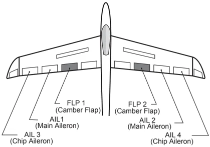
- Touch the [AIL to Camber FLP] button in the Mode Menu to call the setup screen shown below. The display screen is an example. The actual screen depends on the model type.
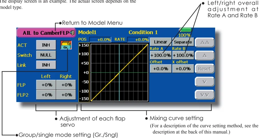
Setting method
- Touch the ACT button and set the function to ACT (ON).
- When setting a switch, touch the [NULL] button of the switch to call the <Switch> screen, and then select the switch and set its ON direction. (Always ON at "NULL" setting) (For a description of the switch selection method, see the description at the back of this manual.)
- Touch the left or right button of each flap servo, and adjust the mixing rate with the adjustment buttons. When the mixing direction is reversed by the linkage, adjustments can be made by changing the mixing rate polarity.
- A mixing curve can be set. (For a description of the mixing curve setting method, see the description at the back of this manual.)
- To set linking, touch the Link button and set it to ON.
84 <Model Menu (Airplane/Glider Functions)>
AIL to Brake FLP [Corresponding model type]: Airplane/glider, 4 flaps or more
This mixing operates the brake flaps (FLP3/4) in the aileron mode. When the aileron stick is manipulated, the aileron and brake flaps perform the aileron operation simultaneously and the operation characteristic of the roll axis is improved.
- The aileron left and right mixing rates can be adjusted for each flap servo.
- A mixing curve can be set.
- Mixing during flight can be turned ON/OFF by setting a stick. (Always ON at NULL setting)
- Linking can be set: Links this mixing to other mixings.
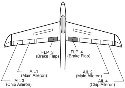
- Touch the [AIL to Brake FLP] button in the Model Menu to call the setup screen shown below.
The display screen is an example. The actual screen depends on the model type.
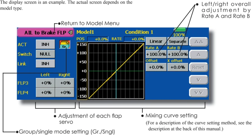
●Setting method
- Touch the ACT button and set the function to ACT (ON).
- When setting a switch, touch the [NULL] button of the switch to call the <Switch> screen, and then select the switch and set its ON direction. (Always ON at "NULL" setting) (For a description of the switch selection method, see the description at the back of this manual.)
- Touch the left or right button of each flap servo, and adjust the mixing rate with the adjustment buttons.
When the mixing direction is reversed by the linkage, adjustments can be made by reversing the mixing rate polarity.
- A mixing curve can be set.
(For a description of the curve setting method, see the description at the back of this manual.)
- To set linking, touch the Link button and set it to ON.
<Model Menu (Airplane/Glider Functions)> 85
AIL to RUD [Corresponding model type]: Airplane/glider, general
Use this mixing when you want to mix the rudders with aileron operation.
- A mixing curve can be set.
- Mixing during flight can be turned ON/OFF by setting a switch. (Always ON at NULL setting)
- The mixing rate can be fine-tuned by setting a VR.
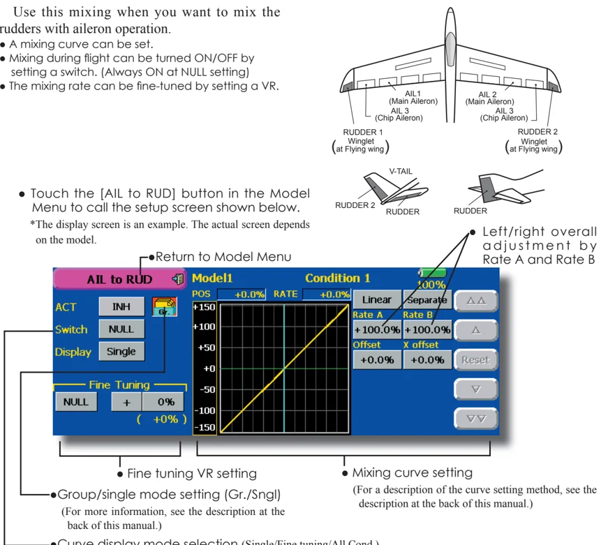
- Touch the [AIL to RUD] button in the Model Menu to call the setup screen shown below. The display screen is an example. The actual screen depends on the model.
- Return to Model Menu
- Fine tuning VR setting
- Group/single mode setting (Gr./Sngl) (For more information, see the description at the back of this manual.)
- Curve display mode selection (Single/Fine tuning/All Cond.)
- Left/right overall adjustment by Rate A and Rate B
- Mixing curve setting (For a description of the curve setting method, see the description at the back of this manual.)
Setting method
- Touch the ACT button and set the function to ACT (ON).
- When setting a switch, touch the [NULL] button of the switch to call the <Switch> screen, and then select the switch and set its ON direction. (Always ON at "NULL" setting) (For a description of the switch selection method, see the description at the back of this manual.)
- When setting a VR, touch the Fine Tuning "NULL" button to call the <Switch> screen, and then select the VR. The adjustment rate and direction can be set. The VR operation mode can also be selected.
- A mixing curve can be set. (For a description of the curve setting method, see the description at the back of this manual.)
- The curve display mode can be changed. Single : Displays the mixing curve only Fine tuning : Displays the mixing rate of the fine tuning VR All Cond. : Displays the mixing curve of all the conditions. (When conditions are set)
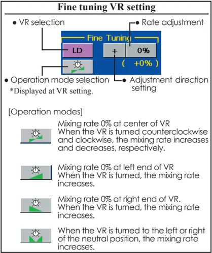
Fine tuning VR setting
- VR selection
- Operation mode selection *Displayed at VR setting.
- Rate adjustment
- Adjustment direction setting
[Operation modes]
Mixing rate 0% at center of VR When the VR is turned counterclockwise and clockwise, the mixing rate increases and decreases, respectively.
Mixing rate 0% at left end of VR When the VR is turned, the mixing rate increases.
Mixing rate 0% at right end of VR. When the VR is turned, the mixing rate increases.
When the VR is turned to the left or right of the neutral position, the mixing rate increases.
86 <Model Menu (Airplane/Glider Functions)>
Airbrake to ELE [Corresponding model type]: Airplane/glider, general
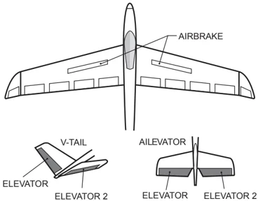
This mixing is used when you want to mix the elevators with airbrake (spoiler) operation. It raises the elevators to correct for drooping of the nose during airbrake operation.
This function does not operate when airbrake is not assigned at the Function menu in the Linkage Menu.
- The Rate 1 side/Rate 2 side mixing rate with the elevator servos can be adjusted.
- A mixing curve can be set.
- Mixing during flight can be turned ON/OFF by setting a switch. (Always ON at NULL setting)
- The mixing rate can be fine-tuned by setting a VR.
- Touch the [Airbrake to ELE] button in the Model Menu to call the setup screen shown below.
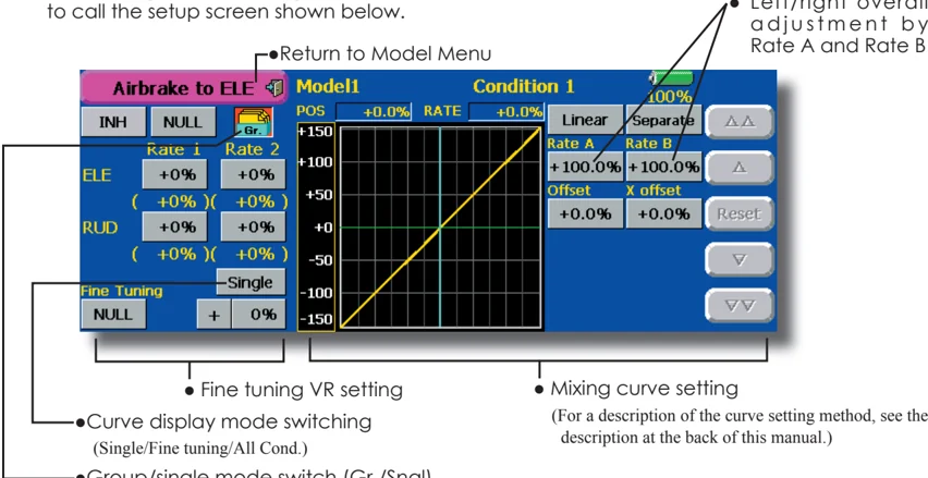
- Return to Model Menu
- Fine tuning VR setting
- Curve display mode switching (Single/Fine tuning/All Cond.)
- Group/single mode switch (Gr./Sngl) (For more information, see the description at the back of this manual.)
- Left/right overall adjustment by Rate A and Rate B
- Mixing curve setting (For a description of the curve setting method, see the description at the back of this manual.)
Setting method
- Touch the "INH" button and set the function to ACT (ON).
- When setting a switch, touch the [NULL] button to call the <Switch> screen, and then select the switch and set its ON direction. (Always ON at "NULL" setting) (For a description of the switch selection method, see the description at the back of this manual.)
- When setting a VR, touch the Fine tuning "NULL" button to call the <Switch> screen, and then select the VR. The adjustment rate and direction can be set. The VR operation mode can also be set. (For a description of the fine tuning VR setting method, see the description at the back of this manual.)
- A mixing curve can be set. (For a description of the curve setting method, see the description at the back of this manual.)
- The curve display mode can be set.
Single : Displays the mixing curve only Fine tuning : Displays the adjustment rate of the fine tuning VR All Cond. : Displays the mixing curve of all the conditions. (When conditions are set)
<Model Menu (Airplane/Glider Functions)> 87
RUD to AIL [Corresponding model type]: Airplane/glider, general
This function is used when you want to mix the ailerons with rudder operation. It is used when rudder is applied during roll maneuvers, knife edge, etc. of stunt planes. It can be used to bank scale models, large models, etc. like a full size plane.
- A mixing curve can be set.
- Mixing during flight can be turned ON/OFF by setting a switch. (Always ON at [NULL] setting)
- The rate of correction rudder can be memorized by using the memory function. This is convenient when setting a mixing curve. When memory operation (switch operation) is performed in the memory mode with correction rudder applied, the switch operation position at that time is displayed
- Touch the [RUD to AIL] button in the Model Menu to call the setup screen shown below.
on the mixing curve. When the memory mode is exited, the memorized points are automatically reflected on the curve. (When the memory function is used, "Line" type curve is automatically selected.)
- Linking can be set: Links this mixing to other mixings.
- The mixing rate can be fine-tune by setting a VR.
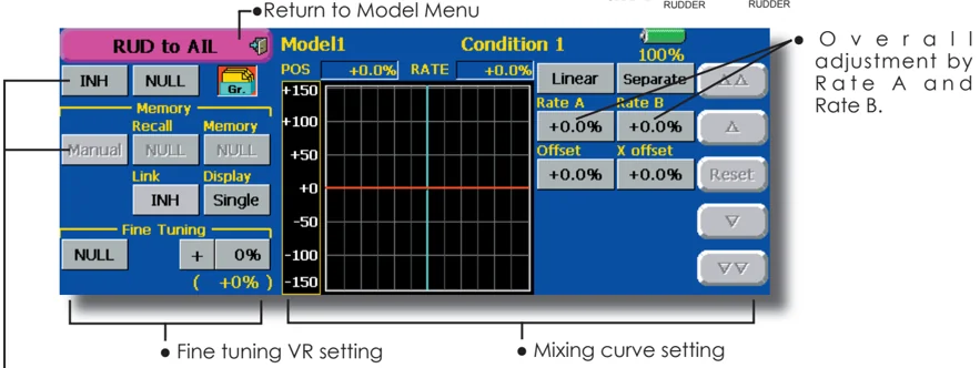
• Return to Model Menu Overall adjustment by Rate A and Rate B. • Fine tuning VR setting • Mixing curve setting (For a description of the curve setting method, see the description at the back of this manual.) • When set to ON by touching [INH], the memory items are displayed.
Setting method
- Touch the "INH" button and set the function to ACT (ON).
- When setting a switch, touch the [NULL] button to call the <Switch> screen, and then select the switch and set its ON direction. (Always ON at "NULL" setting) (For a description of the switch selection method, see the description at the back of this manual.)
- When setting a VR, touch the Fine tuning "NULL" button to call the <Switch> screen and then select the VR. The adjustment rate and adjustment direction can be set,. The VR operation mode can also be set. (For a description of the fine tuning VR setting method, see the description at the back of this manual.)
- A mixing curve can be set. (For a description of the curve setting method, see the description at the back of this manual.)
- The curve display mode can be changed. Single : Displays the mixing curve only Fine tuning : Displays the adjustment rate of the fine tuning VR
All Cond. : Displays the mixing curve of all the conditions. (When conditions are set)
- When linking: Touch the Link button and set it to ON.
Memory function usage method
(Example) Using the memory function with an F3A airplane (knife edge correction)
*When call switch \Rightarrow[SW-A] and memory switch\Rightarrow[SW-H] were set
[Memory function operation]
- Memory function mode: [Manual] \Rightarrow [Memory]
- When the memory switch (SW-H) was set to ON while performing aileron correction when rudder was applied at knife edge, the point position at that time is memorized. Perform memorization while changing the left and right stick positions.
- To recall the memorized positions, set [SW-A] to ON. The memorized correction rate is reflected on the curve, and operation is simultaneously set.
Note: When memorized from manual before flight, be sure that the memory SW is not accidentally set to ON and incorrect mixing setting is not applied when taxiing, starting the engine, etc.
88 <Model Menu (Airplane/Glider Functions)>
Camber Mix [Corresponding model type]: Airplane/glider, 2 ailerons or more
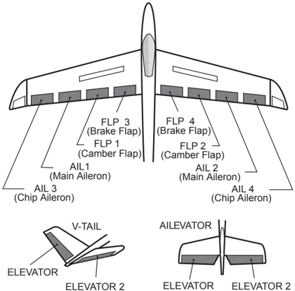
This function adjusts the AFR (D/R) rate of camber operation which operates the wing camber (ailerons, camber flaps, brake flaps) in the negative and positive directions. The aileron, flap, and elevator rates can also be adjusted independently by curve, and attitude changes caused by camber operation can be corrected.
*Initial setting assigns camber operation to side lever LST. • The up/down side rates of the aileron, flap, and elevator servos can be adjusted by curve. When the mixing direction is reversed by the linkage, adjustments can be made by changing the mixing rate polarity.
• Mixing during flight can be turned ON/OFF by setting a switch. (Always ON at NULL setting) • A delay can be set for each condition. A cut switch which can turn OFF the delay function can be set. • The speed of the aileron, flap, and elevator servos can be set. (IN side/OUT side)
• Touch the [Camber Mix] button in the Model Menu to call the setup screen shown below. *The display screen is an example. The actual screen depends on the model type.)
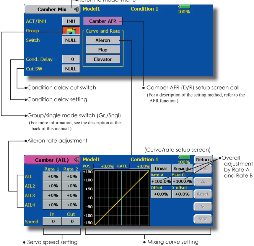
•Return to Model Menu
Camber Mix Model1 Condition 1 100% ACT/INH INH Camber AFR Group Gr. Curve and Rate Switch NULL Aileron Flap Elevator Cond. Delay 0 Cut SW NULL
•Condition delay cut switch •Condition delay setting •Group/single mode switch (Gr./Sngl) (For more information, see the description at the back of this manual.) •Aileron rate adjustment •Camber AFR (D/R) setup screen call (For a description of the setting method, refer to the AFR function.)
(Curve/rate setup screen)
Camber (AIL) Model1 Condition 1 100% Return Rate 1 Rate 2 POS +0.0% RATE +0.0% Linear Separate AIL +0% +0% +150 Rate A Rate B AIL2 +0% +0% +100 +100.0% +100.0% AIL3 +0% +0% +50 Offset X offset AIL4 +0% +0% +0 +0.0% +0.0% Reset In Out -50 Speed 0 0 -100 -150
•Servo speed setting (For a description of the setting method, see the description at the back of this manual.) •Mixing curve setting (For a description of the curve setting method, see the description at the back of this manual.) •Overall adjustment by Rate A and Rate B
<Model Menu (Airplane/Glider Functions)> 89
Setting method
-
Touch the "INH" button and set the function to ACT (ON).
-
When setting a switch, touch the [NULL] button to call the <Switch> screen, and then select the switch and set its ON direction. (Always ON at "NULL" setting) (For a description of the switch selection method, see the description at the back of this manual.)
-
When setting a condition delay, touch the Condition Delay button and set the delay with the adjustment buttons which appear on the screen. The VR operation mode can also be set. (For a description of condition delay, see the description at the back of this manual.)
-
Camber AFR(D/R) screen call Touch the Camber AFR button to call the setup screen. (For a description of the setup method, see the description at the back of this manual.)
(Curve/rate setup screen)
- The curve and rate are adjusted by calling the aileron, flap, and elevator curve/rate screens. The rate and curve of each servo can be set by calling each screen. (For a description of the curve setting method, see the description at the back of this manual.) The servo speed can also be adjusted.
90 <Model Menu (Airplane/Glider Functions)>
ELE to Camber
[Corresponding model type]: Airplane/glider, 2 ailerons or more
This function is used when you want to mix the camber flaps with elevator operation. When mixing is used so that the flaps are lowered by up elevator, lift can be increased.
- A mixing curve can be set.
- Mixing during flight can be turned ON/OFF by setting a switch. (Always ON at NULL setting)
- The mixing rate can be fine-tuned by setting a VR.
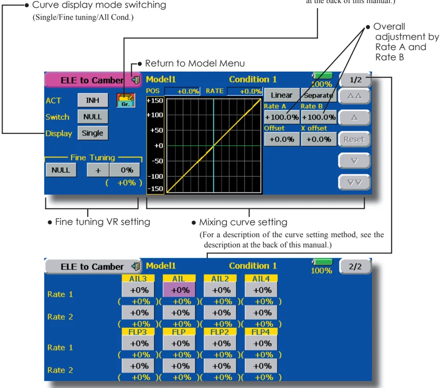
(Ailerons and flaps rate adjustment screen)
Setting method
- Touch the ACT button and set the function to ACT(ON).
- When setting a switch, touch the [NULL] button of the switch to call the <Switch> screen, and then select the switch and set its ON direction. (Always ON at "NULL" setting.)
- When setting a VR, touch the Fine tuning "NULL" button to call the <Switch> screen, and then select the VR. The adjustment rate and adjustment direction can be set. The VR operation mode can also be selected.
- A mixing curve can also be set. (For a description of the curve setting method, see the description at the back of this manual.)
- The curve display mode can be changed. Single : Displays the mixing curve only Fine tuning : Displays the fine tuning VR adjustment rate All Cond. : Displays the mixing curve of all the conditions (When conditions are set)
<Model Menu (Airplane/Glider Functions)> 91
Camber FLP to ELE [Corresponding model type]: Airplane/glider, 2 ailerons + 1 flap or more
This mixing is used to correct changes (elevator direction) generated when the camber flaps (speed flaps) are used.
- The elevator servos up side/down side rate can be adjusted. When the mixing direction is reversed by the linkage, adjustments can be made by changing the mixing rate polarity.
- A mixing curve can be set.
- Mixing during flight can be turned ON/OFF by setting a switch. (Always ON at NULL setting)
- The mixing rate can be fine-tuned by setting a VR.
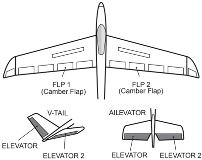
- Touch the [Camber FLP to ELE] button in the Model Menu to call the setup screen shown below.
*The display screen is an example. The actual screen depends on the model type.
- Group/single mode switching (Gr./Sngl) (For more information, see the description at the back of this manual.)
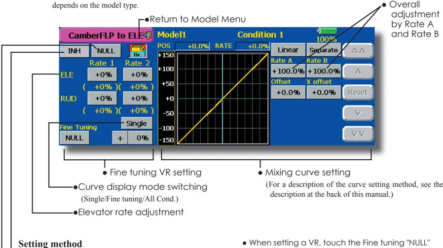
Setting method
- Touch the ACT button and set the function to ACT(ON).
- When setting a switch, touch the switch button to call the <Switch> screen, and then select the switch and set its ON direction. (Always ON at "NULL" setting) (For a description of the switch setting method, see the description at the back of the manual.)
- Touch the elevator servos left and right buttons and adjust the mixing rate with the adjustment buttons displayed on the screen.
*When the mixing direction is reversed by the linkage, adjustments can be made by changing the mixing rate polarity.
- When setting a VR, touch the Fine tuning "NULL" button to call the <Switch> screen, and then select the VR. The VR operation mode can be selected.
- A mixing curve can be set. (For a description of the curve setting method, see the description at the back of this manual.)
- The curve operation mode can be changed. Single : Displays only the mixing curve Fine Tuning : Displays the adjustment rate of the fine tuning VR All Cond. : Displays the mixing curve of all the conditions (when conditions are set)
92 <Model Menu (Airplane/Glider Functions)>
Butterfly [Corresponding model type]: Glider, 2 ailerons or more
This function allows powerful brake operation by simultaneously raising the left and right ailerons and lowering the flaps (camber flap, brake flap).
This setting will allow the ailerons to be raised while the flaps are simultaneously lowered. Butterfly (Crow) produces an extremely efficient landing configuration by accomplishing the following:
- Slow the aircraft's velocity.
- Provide washout at the wing tips to reduce the tendency to tip stall.
- Create more lift toward the center of the wing allowing it to fly at a slower speed
- Mixing during flight can be turned ON/OFF by setting a switch. (Always ON at NULL setting)
- The butterfly operation reference point can be offset. When the Offset button is touched when operated to the position to be changed, the reference point is offset. If the reference point is offset too much, unexpected operation may be performed.
- The ailerons, flaps, and elevators operation speed can be adjusted. (IN side/OUT side)
- A delay can be set for each condition. A cut switch which can turn OFF the delay function can also be set.
- The differential rate can be adjusted.
*When servo binding occurs when setting the ailerons and flaps in butterfly mixing, use the AFR function to adjust the rudder angle.
- Touch the [Butterfly] button in the Model Menu to call the setup screen shown below. (The display screen is an example. The actual screen depends on the model type. The screen shown below is for 4 ailerons and 4 flaps.)
- Touch the ACT button and set the function to ACT (ON).
- When setting a switch, touch the SWITCH [NULL] button to call the <Switch> screen, and then select the switch and set its ON direction.
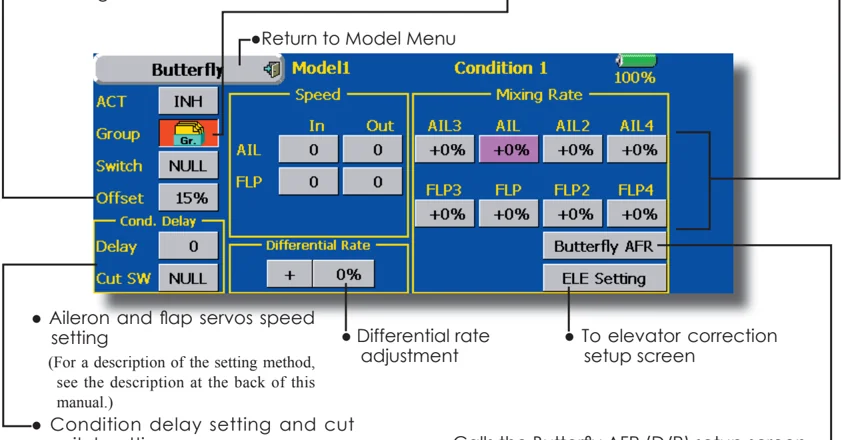
-
Group/single mode switching (Gr./Sngl) (For more information, see the description at the back of this manual.)
-
When offsetting the butterfly operation reference point, operate to the point you want to change and then touch the Offset button. The reference point displays 0%. When [Yes] is touched, the reference point is changed.
-
Touch the Mixing Rate AIL and FLP buttons and adjust the mixing rates.
-
Return to Model Menu
-
Aileron and flap servos speed setting (For a description of the setting method, see the description at the back of this manual.)
-
Differential rate adjustment
-
To elevator correction setup screen
-
Condition delay setting and cut switch setting (For a description of the setting method, see the description at the back of this manual.)
-
Calls the Butterfly AFR (D/R) setup screen (For a description of the setting method, see the description at the back of this manual.)
<Model Menu (Airplane/Glider Functions)> 93
• Touch the ELE correction rate buttons and adjust the rates with the adjustment buttons displayed on the screen.
([ELE Setup] screen)
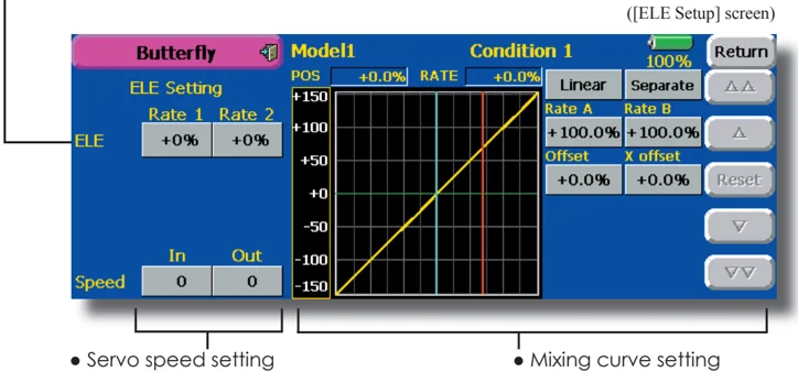
• Servo speed setting (For a description of the setting method, see the description at the back of this manual.)
• Mixing curve setting (For a description of the curve setting method, see the description at the back of this manual.)
94 <Model Menu (Airplane/Glider Functions)>
Trim Mix 1/2 [Corresponding model type]: Glider, 2 ailerons or more
These functions call the ailerons, elevators, and flaps (camber flaps, brake flaps) trim offset rates preset according to the flight state.
The amount of ailerons, elevator, and flaps (camber flap, brake flap) trim offset can be set to a switch.
As an example Trim Mix 1 can be set up for launching, with speed flaps and ailerons dropped, and a slight amount of up elevator. Trim mix 2 can be used for high speed flying, with both ailerons and speed flaps reflexed slightly, and a bit of down elevator.
The trim functions can be activated during flight by setting a switch. To prevent sudden trim changes when switching flight conditions, a delay can be set to provide a smooth transition between the two. Trim Mix 2 will have priority over Trim Mix 1.
Example
- Touch the ACT button and set the trim mix function to [ON]. *When separating the settings for each condition, touch the group mode button and set it to [Sngl].
- Select the ON/OFF switch.
- Select the [Manual] or [Auto] mode. In the [Auto] mode, also select an auto SW. This switch can be linked to a stick, etc. <Speed> In: The operation speed at switch ON can be set. Out: The return speed at switch OFF can be set. <Fine Tuning> The offset rate can be varied in the Fine Tuning numeric range set at screen [1/2] by VR, etc. selection. <Condition Delay> When flight conditions are set, the operation speed can be set for each condition. Condition delay operation can be interrupted and each rudder quickly returned to its original position by selecting a cut switch.
- Touch the [Trim Mix 1] button in the Model Menu to call the setup screen shown below. (The display screen is an example. The actual screen depends on the model type. The screen shown below is for 4 ailerons and 4 flaps.) (Touch the [1/2] button to switch to page 2.)
- Touch the ACT button and set the function to ACT (ON).
- When setting a switch, touch the Switch button to call the <Switch> screen, and then select the switch and set its ON direction. (Always ON at "NULL" setting) (For a description of the switch selection method, see the description at the back of this manual.)
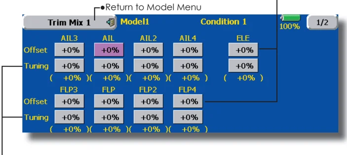
- Return to Model Menu
- The ailerons, flaps, and elevators offset rate can be adjusted. Touch the corresponding button and adjust the rate with the adjustment buttons displayed on the screen.
- When a fine tuning VR is set on the next page (2/2), the ailerons and flaps trim rates can be adjusted. Touch the corresponding button and adjust the rate with the adjustment buttons displayed on the screen.
<Model Menu (Airplane/Glider Functions)> 95
• Group/single mode switching (Gr./Sngl) (For more information, see the description at the back of this manual.)
• When using a fine tuning VR, touch this button to call the <Switch> screen.
Return to Model Menu (Trim mix setup page 2/2)
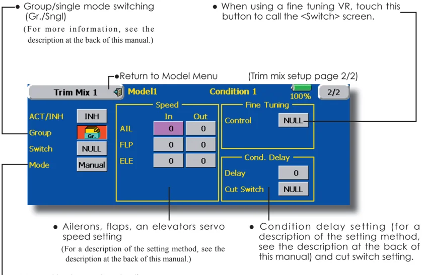
• Ailerons, flaps, an elevators servo speed setting (For a description of the setting method, see the description at the back of this manual.)
• Condition delay setting (for a description of the setting method, see the description at the back of this manual) and cut switch setting.
•Manual/Auto mode selection Manual: Switches the function ON/OFF by switch Auto: Trim mix function call can be linked to a stick, etc. A stick switch, etc. separate from the function ON/OFF switch is set.
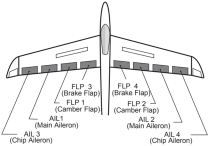
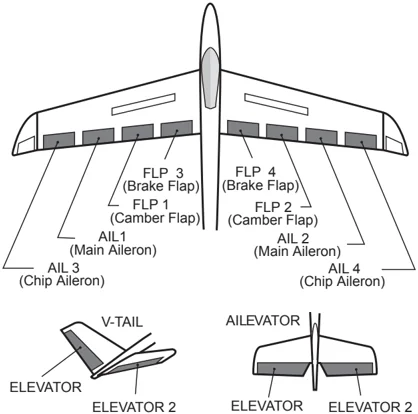
FLP 3 (Brake Flap) FLP 1 (Camber Flap) AIL1 (Main Aileron) AIL 3 (Chip Aileron)
FLP 4 (Brake Flap) FLP 2 (Camber Flap) AIL 2 (Main Aileron) AIL 4 (Chip Aileron)
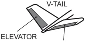
V-TAIL ELEVATOR ELEVATOR 2
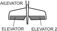
AILEVATOR ELEVATOR ELEVATOR 2
96 <Model Menu (Airplane/Glider Functions)>
Airbrake [Corresponding model type]: Airplane, general
This function is used when an air brake is necessary when landing or diving, etc.
The preset elevators and flaps (camber flap, brake flap) offset amount can be activated by a switch.
The offset amount of the aileron, elevator, and flap servos can be adjusted as needed. Also the speed of the aileron, elevator, and flap servos can be adjusted. (IN side/OUT side) A delay can be set for each condition, and a Cut switch which will turn OFF the delay can be chosen. Trim amounts can be fine-tuned by setting a VR You can also set the Auto Mode, which will link Airbrake to a stick, switch, or dial. A separate stick switch or dial can also be set as the ON/OFF switch.
Setting example for F3A and other flaperon specifications
(When 2 ailerons model type selected) (Page 1/2) Offset rate: AIL: [-35~-45%], AIL2: [-35~-45%], ELE: [+5|7%]
Note: The input numerics are examples. Adjust the travel to match the fuselage.
(Screen 2/2) ACT: [ON] Group: [Sngl] Switch: [SC-C] Mode: [Manual]
- Touch the [Airbrake] button in the Model Menu to call the setup screen shown below. (The display screen is an example. The actual screen depends on the model type. The screen shown below is for 4 ailerons and 4 flaps.) (Touch the [1/2] button to switch to page 2.)
- Touch the ACT button and set the function to ACT(ON).
- When setting a switch, touch the Switch button to call the <Switch> screen, and then select the switch and set its ON direction. (Always ON at "NULL" setting) (For a description of the switch selection method, see the description at the back of this manual.)
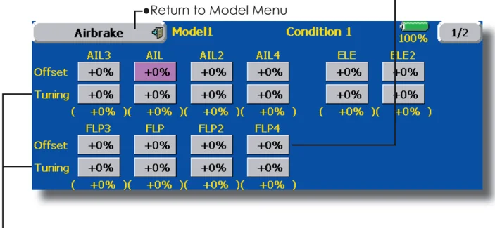
- The aileron, flap, and elevator offset rates can be adjusted. Touch the corresponding button and adjust the rate with the adjustment buttons displayed on the screen.
- When a fine tuning VR is set on the next screen (2/2), the aileron and flap trim rates can be adjusted. Touch the corresponding button and adjust the rates with the adjustment buttons displayed on the screen.
<Model Menu (Airplane/Glider Functions)> 97
• Group/single mode switching (Gr./$ngl) (For more information, see the description at the back of this manual.)
• When using a fine tuning VR, touch this button to call the <Switch> screen.
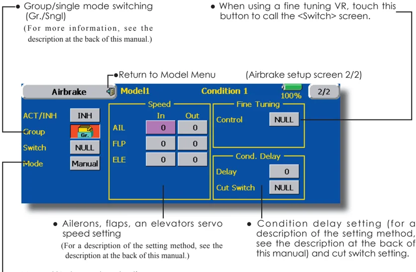
• Return to Model Menu (Airbrake setup screen 2/2)
ACT/INH INH Group Gr. Switch NULL Mode Manual
Speed In Out AIL 0 0 FLP 0 0 ELE 0 0
Fine Tuning Control NULL
Cond. Delay Delay 0 Cut Switch NULL
• Ailerons, flaps, an elevators servo speed setting (For a description of the setting method, see the description at the back of this manual.)
• Condition delay setting (for a description of the setting method, see the description at the back of this manual) and cut switch setting.
• Manual/Auto mode selection Manual: Switches the function ON/OFF by switch Auto: Trim mix function call can be linked to a stick, etc. A stick switch, etc. separate from the function ON/OFF switch is set.
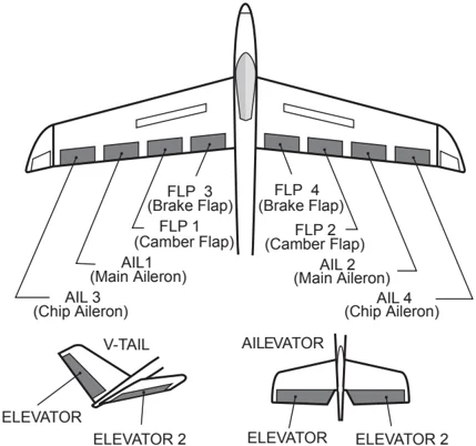
FLP 3 (Brake Flap) FLP 4 (Brake Flap) FLP 1 (Camber Flap) FLP 2 (Camber Flap) AIL 1 (Main Aileron) AIL 2 (Main Aileron) AIL 3 (Chip Aileron) AIL 4 (Chip Aileron)
V-TAIL ELEVATOR ELEVATOR 2
AILEVATOR ELEVATOR ELEVATOR 2
98 <Model Menu (Airplane/Glider Functions)>
Gyro [Corresponding model type]: Airplane/glider, general
This function is used when a GYA Series gyro is used to stabilize the fuselage attitude. The sensitivity and operation mode (Normal mode/GY mode) can be switched with a switch.
- Three rates (Rate 1/Rate 2/Rate 3) can be switched.
- Up to 3 axes (Gyro/Gyro 2/Gyro 3) can be simultaneously controlled.
*Initial setting does not assign a sensitivity channel. Use the Function menu of the Linkage Menu to assign the sensitivity channel (Gyro/Gyro2/Gyro3) used to a vacant channel beforehand.
Set [ACT] and [Trim] other than Function to [NULL].
- Touch the [Gyro] button in the Model Menu to call the setup screen shown below.
- Group/single mode switching (Gr./Sngl) (For more information, see the description at the back of this manual.)
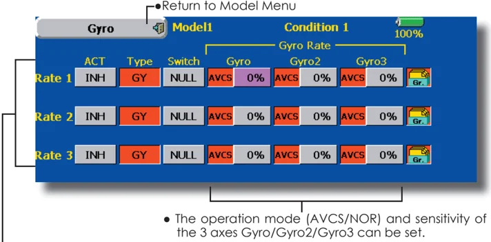
- Return to Model Menu
- The operation mode (AVCS/NOR) and sensitivity of the 3 axes Gyro/Gyro2/Gyro3 can be set.
- Three rates (Rate 1/Rate 2/Rate 3) can be used.
- Touch the ACT button of the rate to be used, and set the function to ACT ([ON] or [OFF]).
- When a Futaba GYA gyro is used, when [GY] type is selected, the sensitivity set value is directly read in both the AVCS and NOR modes.
- When setting a switch, touch the switch button to call the <Switch> screen, and then select the switch and set its ON direction. (For a description of the switch selection method, see the description at the end of this manual.)
(Example) Setting 3 axes using a GYA351 and GYA352 (2 axes gyro)
- Wing type: Aileron 2 servos mounted fuselage selected
- Set Gyro 1 (GYA351): CH7, Gyro 2 (GYA352): CH8, Gyro 3 (GYA352): CH9 at the Function menu of the Linkage Menu.
- Rate 1 [OFF][GY][SW-E][NOR][60%][NOR][60%][NOR][60&][Gr] Rate 2 [INH][GY][NULL][AVCS][0%][AVCS][0%][AVCS][0%][Gr] Rate 3 [OFF][GY][SE-E][AVCS][60%][AVCS][60%][AVCS][60%][Gr] *When separating the conditions, set to [Sngl]. *Set so that Rate 1 is turned on at the back position of switch E and Rate 3 is turned ON at the front position. Since switch E is turned OFF at the center, Rate 2 remains [INH].
<Model Menu (Airplane/Glider Functions)> 99
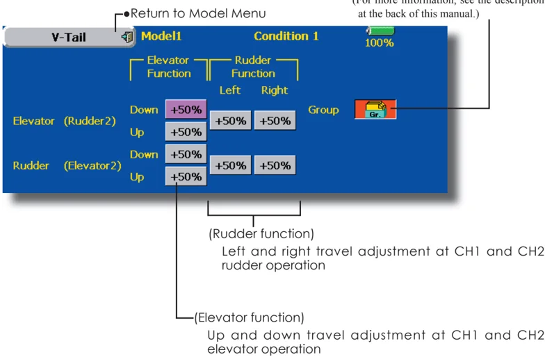
V-tail [Corresponding model type]: Airplane/glider, V-tail
This function let’s you adjust for left and right rudder angle changes at elevator and rudder operation of a V-tail airplane.
V-tail is when 2 servos are used together to control rudder movement as Elevators. In addition to each rudder side moving up and down together, each side moves in opposite directions when moving as Elevators. On a V-tail, this is also known as a Ruddervator, as they can serve the same purpose.
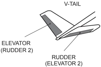
- Touch the [V-tail] button in the Model Menu to call the setup screen shown below.
- Group/single mode switching (Gr./Sngl) (For more information, see the description at the back of this manual.)
100 <Model Menu (Airplane/Glider Functions)>