 LITHIUM-ION BATTERY
●Reset Button
Futaba
How to reset software
If the screen freezes for some reason and you cannot edit, the transmitter power supply is not shut off even if you turn OFF the power switch. You will need to use the reset button or remove the battery and reinsert it again. In this case, the power restarts in "Cold mode". Even though the screen freezes, all the other functions for radio control operation remain operative.
How to change the frequency/How to set ID
The T14MZ system has employed the frequency synthesizer scheme. The T14MZ transmitter will set the frequency of the R5014DPS (PCMG3 receiver) by the wireless data transmission. When you are using a new PCMG3 receiver and changing the frequency, set ID or frequency by the following instructions.
In case of using PCMG3 receivers
*Make sure that PCM-G3 is set as a modulation scheme. Then change the frequency by the following instruction.
How to change the frequency
- Turn on the power of the transmitter.
- Push the area that shows the frequency in the home screen or push the "Frequency" button in the Linkage menu. Then the Frequency Set screen will pop up.
 Frequency Model1 100%
Band No. (Freq. CH) 11 (72.010 MHz)
Frequency Band 72MHz
Area America
Modulation PCM-G3
Receiver ID 00001001
2nd Receiver ID No Use
- Push the "Receiver ID" button. Then ID inputting screen for receiver will pop up. Input the eight-digit ID code attached to the receiver's case. Push the "Yes" button after confirming the ID. *Use the "BS" button to move back digit by digit for correction if you made a mistake. If you want to stop changing ID code halfway, push "Return" button to return to the previous screen. *Once you set the ID code for a receiver, you don't have to set the ID code again as long as you change the receiver itself. *When you need to use two receivers for a large size aircraft, you need to enter different ID codes to those receivers respectively.
- Push the "Band NO. (Frequency)" button if you need to change the frequency. Then you will see frequencies on the screen. Select the frequency you want use. Push the button "Yes" after confirmation. Then you will see the "Confirmation of the change" box. *If you have changed the module prior to turning on the power, confirmation screen will pop up to ask you whether you want to change the frequency. Push the button "Yes" to change the frequency.
- If the frequency is correct, push the button "Yes". Then you will see the message "Transmitting the frequency data". It takes a certain time to send the new frequency data to the receiver with a sound. (If you need to resend the data, push the "Resend" button.)
- Turn on the power of the receiver while the
26 <Basic Operation>
new frequency data is displayed. When the frequency setting for the receiver is completed, the LED monitor of the receiver blinks once and the 1CH servo shuttles three times across the neutral position.
*A very low power, whose frequency is different from that of the channel frequency, is used to set the frequency of the receiver. The reachable distance of the radio is designed to be within several feet. Therefore, put the transmitter and the receiver as close as possible when setting the frequency of the receiver.
- If the receiver can not load the new data due to environmental reasons, connect the transmitter and the receiver directly by the DSC cable. And do the procedure 6 and 7.
*LED monitor will blink on and off if the receiver's ID code is wrong. Then move back to the Receiver ID Set screen and restart the receiver's ID setting from the beginning.
- Push the button "End" when the frequency setting is completed. Then turn off the power of the transmitter following the instructions shown on the screen. You will be able to use the new frequency after you turn on the power again.
In case of using PCM1024, PPM receivers
*Make sure that PCM1024 or PPM is set as a modulation scheme. Then change the frequency by the following instruction.
How to change the frequency
- Turn on the power of the transmitter.
- Push the area that shows the frequency in the home screen or push the "Frequency" button in the Linkage menu. Then the Frequency Set screen will pop up.
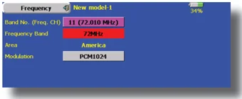
- Push the "Band NO. (Frequency)" button if you need to change the frequency. Then you will see frequencies on the screen. Select the frequency you want use. Push the button "Yes" after confirmation. Then you will see the "Confirmation of the change" box.
*If you have changed the module prior to turning on the power, confirmation screen will pop up to ask you whether you want to change the frequency. Push the button "Yes" to change the frequency.
- If the frequency is correct, push the button "Yes". Turn off the power of the transmitter following the instructions shown on the screen. You will be able to use the new frequency after you turn on the power again.
Registration of the user's name
T14MZ transmitter can register user's name.
How to register user's name
- Turn on the power of the transmitter.
- Push the area of the user's name shown on the home screen or the "user's name" in the linkage menu. Then the User's Name Set screen will pop up.
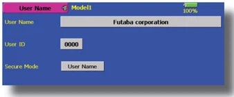
- Push the user's name. Then the keyboard will pop up. You can use up to 32 characters as a user's name. Use the keyboard on the screen to enter user's name.
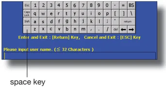
space key
- Push "Return" key to return to the previous screen after entering the user's name.
(If you want to protect the user's name)
If you don't want anybody else to change your user's name, set your ID in the following way.
*Please be aware that you will not able to change user's name if you forget your password.
- Make sure that the security mode is "User's name", and then push the User ID button.
- Enter your password, using keyboard on the screen.
You will need to enter your password for changing the user's name from the next time you turn on the power of the transmitter.
*Even if you enter the same character, your password will be identified differently depending on whether you are using "Transform" mode or "Direct" mode for inputting.
Home screen
Here is the home screen and its descriptions. Use your finger or included stylus pen to operate the touch screen.
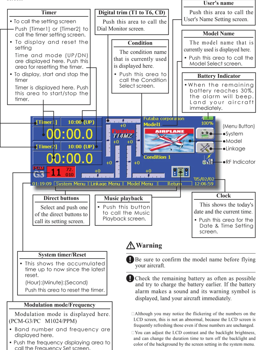
Timer
- To call the setting screen Push [Timer1] or [Timer2] to call the timer setting screen.
- To display and reset the setting Time and mode (UP/DN) are displayed here. Push this area for resetting the timer.
- To display, start and stop the timer Timer is displayed here. Push this area to start/stop the timer.
Digital trim (T1 to T6, CD) Push this area to call the Dial Monitor screen.
Condition The condition name that is currently used is displayed here.
- Push this area to call the Condition Select screen.
User's name Push this area to call the User's Name Setting screen.
Model Name The model name that is currently used is displayed here.
- Push this area to call the Model Select screen.
Battery Indicator
- When the remaining battery reaches 30%, the alarm will beep. Land your aircraft immediately.
(Callouts on the right side of the screen image)
- (Menu Button)
- System
- Model
- Linkage
- RF Indicator
Direct buttons Select and push one of the direct buttons to call its setting screen.
Music playback
- Push this button to call the Music Playback screen.
Clock This shows the today's date and the current time.
- Push this area for the Date & Time Setting screen.
System timer/Reset
- This shows the accumulated time up to now since the latest reset. (Hour):(Minute):(Second) Push this area to reset the timer.
Modulation mode/Frequency Modulation mode is displayed here. (PCM-G3/PC M1024/PPM)
- Band number and frequency are displayed here.
- Push the frequency displaying area to call the Frequency Set screen.
⚠ Warning
! Be sure to confirm the model name before flying your aircraft.
! Check the remaining battery as often as possible and try to charge the battery earlier. If the battery alarm makes a sound and its warning symbol is displayed, land your aircraft immediately.
Although you may notice the flickering of the numbers on the LCD screen, this is not an abnormal, because the LCD screen is frequently refreshing those even if those numbers are unchanged.
You can adjust the LCD contrast and the backlight brightness, and can change the duration time to turn off the backlight and color of the background by the screen setting in the system menu.
28 <Basic Operation>
Music playback
The T14MZ transmitter can play back the ".wma" music files stored in the CF (Compact Flash) card. You can listen to them through the built-in speaker or a headphone by the earphone plug.
*First, store music files from your PC into the WMA folder on the CF card, and then insert the CF card into your transmitter to play back music files on the transmitter.
[Important notice]
Before downloading files from your PC into the CF card, insert the CF card into the transmitter and turn on the power of the transmitter. Then the following folders will be automatically created in the CF card. When you download files from you PC, copy and paste the files into their corresponding files.
- BMP : picture files
- WMA : music files
- WAV : sound files
- MODEL : model data files
• Push the Music Playback button on the home screen to call the following set-up screen.
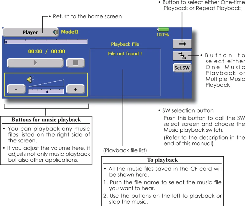
• Return to the home screen
• Button to select either One-time Playback or Repeat Playback
• Button to select either One Music Playback or Multiple Music Playback
Buttons for music playback
- You can playback any music files listed on the right side of the screen.
- If you adjust the volume here, it adjusts not only music playback but also other applications.
(Playback file list)
To playback
- All the music files saved in the CF card will be shown here.
- Push the file name to select the music file you want to hear.
- Use the buttons on the left to playback or stop the music.
• SW selection button Push this button to call the SW select screen and choose the Music playback switch. (Refer to the description in the end of this manual)
<Basic Operation> 29
SYSTEM MENU
The System Menu sets up functions of the transmitter, this does not set up any model data.
When the System Menu button is touched, the menu shown below is called. Call the setup screen by pressing the function you want to set up.
 Return to Home screen
System Menu Model1 Condition 1 100% 1/1 Trainer Display Date and Time User Name Switch H/W Reverse Information System Menu Linkage Menu Model Menu Return
System Menu functions table
[Trainer]: Starts and sets the trainer system. [Display]: Display adjustment and auto power off setting. [Date & Time]: Sets the date and time (system clock setting) and resets the timer. [User Name]: User name registration and ID Pin number. [Switch]: Toggle switch type setting (Set when the switch is replaced.) [H/W Reverse]: Reverses the direction of operation of the sticks, switches, trim levers, knobs, etc. [Information]: Displays the program version, CF card information, and product ID.
Trainer
Trainer system starting and setting
The Trainer function makes it possible for the instructor to choose which functions and channels are to be used for instruction, making it possible to match the training ability to the student's skill level. Two transmitters must be connected by an optional Trainer Cord, and the Instructors' transmitter should be programmed for trainer operation, as described below.
When the Instructor activates the trainer switch, the student has control of the aircraft (if MIX or FUNC mode is turned on, the Instructor can make corrections while the student has control). When the switch is released the Instructor regains control. This is very useful if the student gets the aircraft into an undesirable situation.
NOTE: This trainer system can be used in the following manner;
- In the T14MZ transmitter and a conventional transmitter, if the channel order is different. It is necessary to match the channel order in the Linkage Menu when connecting it with other than a T14MZ.
- When the T14MZ is used as the Teacher, set the modulation mode of the student's transmitter to PPM. If being used as the student, set the T14MZ to the modulation mode specified by the Instructors' transmitter. When the Instructors' transmitter is a T14MZ, T9Z, T9C or T7C transmitter, it should be switched to PPM mode.
- Be sure that all channels work correctly in both transmitters before flying.
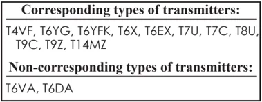
- Touch the [Trainer] button at the System Menu to call the setup screen shown below.
\begin{tabular}{|l|} \hline Corresponding types of transmitters: \ \hline T4VF, T6YG, T6YFK, T6X, T6EX, T7U, T7C, T8U, \ T9C, T9Z, T14MZ \ \hline Non-corresponding types of transmitters: \ \hline T6VA, T6DA \ \hline \end{tabular}
 (The display screen is an example. The screen depends on the model type.)
Teacher mode
- Set "Teacher/Student" button to "Teacher".
- Change "ACT/INH" button from "INH" to "OFF" or "ON".
- Set "12CH/8CH" to "12CH" when the student is using T14MZ. Otherwise set it to "8CH".
- Call up the Switch Setting screen by touching "Switch". Then set the desired switch and on/off direction.
- Select the switch mode. If you select "NORM", the trainer function will be turned on or off by a switch position. If you select "ALT", ON and OFF of the trainer function switches alternatively every time the switch is turned on. This means the student side can be operated without holding the switch lever.
- The Instructor side selects the channel for control. Three operating modes are available.
"NORM" mode (Normal mode); Student side has no control of mixes and settings in Teachers radio..
"MIX" mode; Student has full advantage of all setting in Teachers radio, plus Teacher has the option to change any setting while Student has control.
"FUNC" mode (Function mode); Student has control of mixes and rate settings of Teachers radio.
[Notes]
- In the teacher mode, the trainer function display does not come on as long as the student's transmitter is not receiving signals from the teacher's transmitter (when the student's transmitter is not connected).
<Functions of System Menu> 31
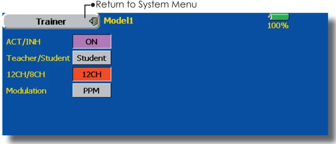
Student mode
- Set "Teacher/ Student" button to "Student".
- Change "ACT/INH" button from "INH" to "OFF" or "ON".
- Set "12CH/8CH" to "12CH" when the Instructor is using the T14MZ. Otherwise set it to "8CH".
Note: In "student mode", only the teacher side can turn on and off the power of the student's transmitter. Keep the power switch always at off position. Note: In "teacher mode", the trainer function won't be turned on unless the Instructors' transmitter receives signals from the student's transmitter. Be sure to confirm this after connecting your trainer cable.
•The setup screen for the student mode is shown below.
32 <Functions of System Menu>
Display
LCD screen adjustment and auto power off setting
The following LCD screen adjustments and auto power off setting are possible:
-
Contrast adjustment
-
Auto power off time setting
-
Backlighting brightness adjustment
-
Background color change
-
Touch panel screen position correction
-
Touch the [Display] button in the System Menu to call the setup screen shown below.
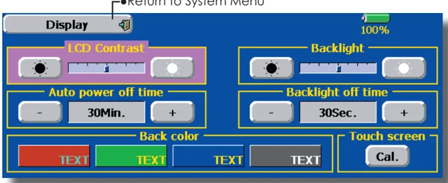
LCD contrast adjustment
- Adjust the LCD contrast with the left and right side buttons. When the right side button is pressed, the LCD contrast decreases. When the left side button is pressed, the LCD contrast increases.
Auto power off time setting
- Adjust the auto power off time with the left and right side buttons. When the time the transmitter is inactive exceeds the set time, the power is turned off automatically. This time can be set up to 1 hour in 10 minutes increments. The auto power off function can also be deactivated.
Backlighting brightness adjustment
- Adjust the backlighting brightness with the left and right side buttons. When the right side button is touched, the backlighting becomes brighter. When the left side button is touched, the backlighting becomes darker.
Backlight power-off time You can set a time period to turn off the LCD backlight. This function counts the period that the touch panel has been not operated. This time can be set by ten-second steps. You can also turn off the backlight-power-off" if you like.
*The backlight consumes a large amount of power. We recommend you to turn off the backlight by setting the backlight power-off time to about one minute.
*Since the backlighting power consumption is extremely high, we recommend that the backlighting off time be made short.
Background color
- Touch the button of the color you want to change. There are four background colors.
Touch panel calibration This function adjusts the location of touch panel. Touch "Calibration" button and then press "Yes", the calibration screen will pop up. Touch the center of the cross hair cursor on the screen with the stylus pen. As soon as the system recognizes the position, the cursor will move on to the next position. Repeat this procedure as long as the cursor moves to next position. You will do this five times. Calibration will be carried out based on the five positions. Disappearance of the cross hair cursor means the calibration has been completed. Touch any point on the screen to return to the previous screen.
In ordinary operation, this calibration is not necessary. If you notice the touch panel is not functioning correctly after long use, we recommend you to carry out this calibration.
<Functions of System Menu> 33
Date and Time
Date and time setting (system clock setting) and integrating timer resetting
This function adjusts the system clock of the T14MZ transmitter. Perform this setting when you purchase the set and when adjustment is necessary.
The integrating timer can also be reset. *The integrating timer is displayed on the Home screen.
- Touch the [Date and Time] button in the System Menu to call the setup screen shown below.
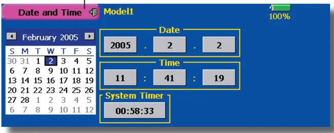
Date setting
- Touch the "Year", "Month", or "Day" button and set the date by touching the [+] or [-] button. *The date can also be set by pressing the date on the calendar shown at the left.
Time setting
- Touch the "Hour" or "Minute" button, and set the time by touching the [+] or [-] button.
- When the "Second" button is touched, the timer is set to "00" seconds.
Integrating timer reset
The integrating timer shows the total time that has elapsed since the last resetting.
- When the [System Timer] button is touched, the timer is reset.
34 <Functions of System Menu>
User Name
User name registration and PIN setting
This function registers the T14MZ user name. A PIN can also be set to protect the set data or user name.
*Set the PIN carefully. When a system PIN is set, if you forget the PIN, none of the settings can be changed. In this case, the system must be reset by the Futaba Service Center.
- Touch the [User Name] button at the System Menu to call the setup screen shown below.
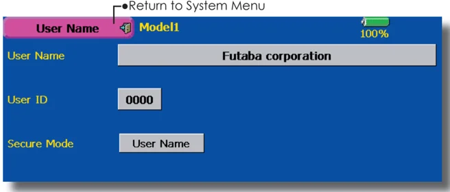
Return to System Menu
User name registration
- When the User Name box is touched, a keyboard appears on the screen.
- Enter the user name from this keyboard. *A user name of up to 32 characters can be entered. *The set user name is displayed on the Home screen. (For a detailed description of the input method, see [User Name Registration/Character Input Method] in the Basic Operation section.)
User name or set data protection
- Touch the Security Mode button and select the mode. The mode is switched each time the button is touched. *User Name: Select when you want to protect the user name only. *System: Select when you want to protect all the set data.
- When the user ID button is touched, a PIN input screen appears. Input a PIN of up to 4 digits.
- When the "Return" key is touched 2 times, the display returns to the preceding screen.
- When the transmitter power is turned off, the set security mode becomes active. *When a PIN is set at the user name, it must be entered the next time the User Name screen is opened. When a System PIN is set, a button displaying a key icon appears on the Home screen. When you want to change the setting, touch this button and enter the PIN.
If you want to nullify your current password, set the password to "0000" (default value).
<Functions of System Menu> 35
Switch Toggle switch type setting (Setting when the switch was replaced.)
If you modify the location of the switches on the right and left (top) of the transmitter, you should be sure to re-assign functions to the switches for proper operation.
A “Lock” is included to prevent settings from being modified by mistake. When you need to change settings, unlock this by pressing “Lock” it will then read "Unlock" and you can make changes as required.
- Touch the [Switch] button at the System Menu to call the setup screen shown below.
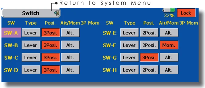
Switch selection
- Select the switch type by touching the [type] button corresponding to the switch to be replaced.
- [Lever]: Toggle switch
- Setting for toggle switch is shown above.
2/3 position selection
- Touch the "Posi," button corresponding to the switch and select the position type.
- [2 Posi]: 2 position
- [3 Posi]: 3 position
[Alt/Mom] mode selection
- Select the operation mode by touching the [Alt/Mom] button corresponding to the switch.
- [Alt.]: Alternate type
- [Mom.]: Self-return type
- Selection of the [Mom.] mode with a 3-position type switch is shown above.
"3P Mom" mode selection
- Select the operation mode by touching the "3P Mom" button corresponding to the switch.
- [Single]: One-side self-return type
- [Dual]: Both directions self-return type
36 <Functions of System Menu>
H/W Reverse Stick, switch, trim lever, and knob operation direction reversal (Hardware reverse)
This function reverses the operation signal of the sticks, switches, trimmer levers, and knobs.
Note: This setting reverses the actual operation signal, but does not change the display of the indicators on the display. Use the Normal mode as long as there is no special reason to use the Reverse mode.
- Touch the [H/W Reverse] button at the System Menu to call the setup screen shown below.
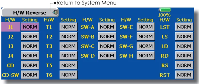
Operation direction reversal method
- Touch the setting button corresponding to the H/W (Hardware) you want to reverse.
- Reverse the H/W by touching [Yes]. (When you want to stop operation, touch [No].) [Normal]: Normal operation direction [Reverse]: Reverses the operation direction.
<Functions of System Menu> 37
Information Displays the program version, CF card information, and product ID.
The T14MZ system program version information, CF card information (memory size, vacant capacity, number of model data, and number of music files), and product ID are displayed on the Information screen.
*When the CF card is not inserted, the CF card information is not displayed.
- Touch the [Information] button at the System Menu to call the setup screen shown below.
 Return to System Menu
Information Model1 100%
Version WindowsCE Ver. 4.20 (0) Editor Ver. 1.0.1 Encoder Ver. 1.03
Memory Card Memory Size 32155136 Bytes Free Space 32119808 Bytes (Model data ... 245 models)
Language English
Product ID 00000000
38 <Functions of System Menu>
MODEL BASIC SETTING PROCEDURE
Airplane/glider basic setting procedure
1. Model addition and call
Initial setting assigns 1 model to the T14MZ transmitter. The Model Select function of the Linkage Menu is used to add models and to call models which are already set.
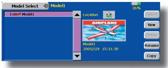
This is convenient when calling a model after its name has been registered. (The data of up to 30 models can be saved to the transmitter. Data can also be saved to the accessory Data-Pack.)
The currently called model name is displayed at the top of the screen. Before flying and before changing any settings, always confirm the model name.
When a new model was added, the Model type select screen and Frequency/Modulation mode/ Receiver ID setup screen automatically appear. After changing or confirming the model, turn the power off and on according to the instructions on the screen. Please be aware that the transmitter will stop transmitting when you change the model.
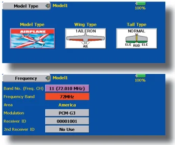
2. Model type selection
Select the model type matched to the fuselage with the Model Type select function of the Linkage Menu. For an airplane, select the model type from among the 3 types: airplane, glider, and motor glider. When the Wing type select screen is displayed and the wing type is selected when selecting the model type, the Tail type select screen is displayed. Select the tail type matched to the fuselage.
There are 13 wing types and 3 tail types for airplane, glider, and motor glider.
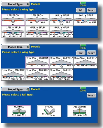
3. Fuselage linkage
Link the ailerons, elevators, throttle, rudder, etc. in accordance with the model's instruction manual. For a description of the connection method, see the Receiver and Servos Connection.
Note: The channel assignment of the T14MZ is different from that of our existing systems. Note that even for the same "airplane model", when the wing type and tail type are different, the channel assignment may be different. (The channel assigned to each function can be checked at the Function menu of the Linkage Menu.)
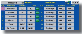
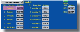
- When the direction of the linkage is reversed, adjust the direction with the Reverse function of the Linkage Menu.
- Connect the throttle linkage so carburetor is open at full trim and full open then the throttle can be cut.
- Adjust the neutral position and rudder angle with the linkage, and fine tune them with the Sub Trim and End Point functions (rudder angle adjustment). To protect the linkage, a limit position can also be set with the End Point function. The End Point function can adjust the amount of up/down and left/right movement, limit, and servo speed of each channel.
<Model Basic Setting Procedure> 39
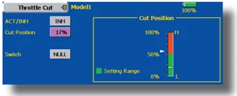
4. Throttle cut setting
Throttle cut can be performed with one touch by a switch without changing the throttle trim position.
Set throttle cut with the Throttle Cut function of the Linkage Menu. After activating the throttle cut function and selecting the switch, adjust the throttle position so that the carburetor becomes full open. For safety, the throttle cut function operates the throttle stick in the 1/3 or less (slow side) position.
5. Idle down setting
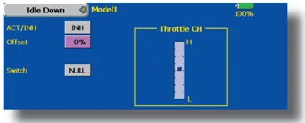
The idling speed can be lowered with one touch by a switch without changing the throttle trim position. Perform this setting with the Idle Down function of the Linkage Menu. After activating the Idle Down function and selecting the switch, adjust the idle down speed. For safety, the idle down function acts only when the throttle stick is in the 1/3 or les (slow side) position.
*While the Throttle Cut function is in operation, the Idle Down function does not work.
6. AFR (D/R)
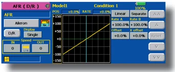
AFR function is used to adjust the throw and operation curve of the stick, lever, and switch functions (CH1 to CH12, and V1 to V4) for each flight condition. This is normally used after End Point (ATV) has defined the maximum throw directions (End Point acts on ALL flight condition settings). When mixing is applied from one channel to another channel, both channels can be adjusted at the same time by adjusting the operation rate through the AFR function.
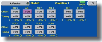
7. Airbrake
This function is used when an air brake is necessary when taking off or diving, etc.
The preset elevators and flaps (camber flap, brake flap) offset amount can be activated by a switch.
The offset amount of the aileron, elevator, and flap servos can be adjusted as needed. Also the speed of the aileron, elevator, and flap servos can be adjusted. (IN side/OUT side) A delay can be set for each condition, and a Cut switch which will turn OFF the delay can be chosen. Trim amounts can be fine-tuned by setting a VR You can also set the Auto Mode, which will link Airbrake to a stick, switch, or dial. A separate stick switch or dial can also be set as the ON/OFF switch.
8. Addition of flight conditions
The transmitter can install up to eight flight conditions per model. You can assign all switches including sticks, switches, trim levers and trim switches as flight-condition selection switches. You can also add delayed mixing to these functions in order to avoid sudden changes. Moreover, you can set priority order for flight conditions when you set more than one condition. In addition, you can copy conditions and/or change names of conditions. This command may also be used to define what switches and/or controls are used to activate each flight condition.
The Condition Select function automatically allocates the Condition 1 for each model type. Condition 1 is the default condition, also referred to as Normal, and is the only one active when a new model type is defined. This condition is always on, and remains on until other conditions are activated by switches.
The Condition Delay can be programmed for each channel. The Condition Delay is used to change the servo throw smoothly when switching conditions.
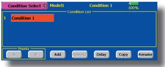
*When a new condition is added, "Condition1" data is automatically copied.
*Select the condition switch and set the new condition data in the switch ON state. However, if the group mode (Gr.) was selected in advance, the same data will be input at all the conditions. Select the single mode (Sngl) and adjust the condition you want to change.
9. When tailless wing model selected
Tailless wing elevator operation uses elevator→camber mixing. This function cannot be performed at initial setting.
Helicopter basic setting procedure
1. Model addition and call
Default setting assigns 1 model to the T14MZ. To add new models or to call a model already set, use the Model Select function of the Linkage Menu.
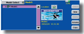
This is convenient when calling a model after registering the model names in advance. (The data of up to 30 models can be saved at the transmitter. Data can also be saved to the accessory Data-Pack.)
The currently called model is displayed at the top of the screen. Before flying and before changing any settings, always confirm the model name.
Please be aware that the transmitter will stop transmitting when you change the model.
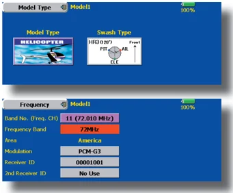
When a new model is added, the Model Type Select screen and Frequency/Modulation mode/Receiver ID setup screen automatically appear. Change, or check that they match the type, frequency, and receiver type of the model used.
2. Model type and swash type selection
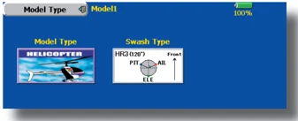
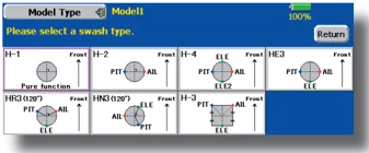
When a separate model type is already selected, select helicopter with the Model Type function of the Linkage Menu, and then select the swash type matched to the fuselage.
3. Flight condition addition
The transmitter can install up to eight flight conditions per model. You can assign all switches including sticks, switches, trim levers and trim switches as flight-condition selection switches. You can also add delayed mixing to these functions in order to avoid sudden changes. Moreover, you can set priority order for flight conditions when you set more than one condition. In addition, you can copy conditions and/or change names of conditions. This command may also be used to define what switches and/or controls are used to activate each flight condition.
The Condition Select function automatically allocates the Condition 0 for each model type. Condition 0 is the default condition, also referred to as Normal, and is the only one active when a new model type is defined. This condition is always on, and remains on until other conditions are activated by switches.
The Condition Delay can be programmed for each channel. The Condition Delay is used to change the servo throw smoothly when switching conditions.
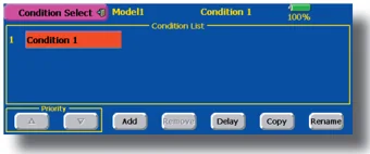
(General flight condition setting example)
- Normal: (Use initial setting conditions/operate when switch OFF) Use from engine starting to hovering.
- Idle up 1: (Switch setting example: Operate at SW-E center) Use in 540o stall turn, loop, rolling stall turn, and other maneuvers.
- Idle up 2: (Switch setting example: Operate at SW-E forward side) Use in rolls.
- Throttle hold: (Switch setting example: Operate at SW-G forward side) Use in auto rotation.
The priority is throttle hold/idle up 2/idle up 1/normal. Throttle hold has the highest priority.
Add other conditions, as required.
<Model Basic Setting Procedure> 41
4. Fuselage linkage
Connect the throttle rudder, ailerons, elevators, pitch, and other rudder linkages in accordance with the kit instruction manual. For a description of the connection method, see "Receiver and Servos Connection".
*The channel assignment of the T14MZ is different from that of our existing systems. (The channel assigned to each function can be checked at the Function menu of the Linkage Menu.)
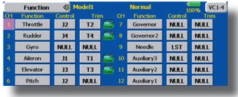
- When the direction of operation of the linkage is reverse, use the Reverse function of the Linkage Menu. Also use the swash AFR function in other than the H-1 mode.
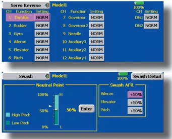
- Adjust the direction of operation of the gyro. (Gyro side function)
- Connect the throttle linkage so that the carburetor becomes full open at full trim throttle cut is possible.
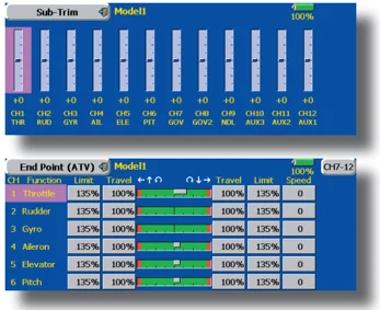
- Basically, adjust the neutral position and rudder angle at the linkage side and fine tune with the Sub-Trim function and End Point function (rudder angle adjustment). To protect the linkage, a limit position can also be set with the End Point function.
- Swash plate correction (Except H-1 mode) Operation of the swash plate near the hovering point can be corrected by swash AFR function correction mixing. Use this when pitch, aileron, and elevator operation causes the swash plate to deviate from the normal direction.
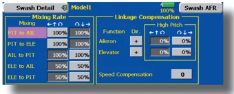
(Call the Swash setup→Swash details screen.) Pitch slow side and high side linkage correction is also possible. Adjust so that pitch operation causes the swash plate to move up and down in the horizontal state.
5. Throttle curve setting
This function adjusts the pitch operation curve in relation to the movement of the throttle stick for each condition.
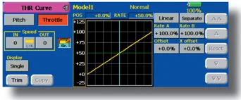
(17 points curve)
The pitch curve can be freely selected from linear operation curve to smooth curve, and adjusted to match the curve you want by means of the T14MZ's powerful Curve Edit Function (6 types of curves can be selected). Up to 17 points can be set for linear or curve types. However, when using the 3 points or 5 points specified to create a curve, a simple and smooth curve can be created by selecting the curve type and reducing the number of input points to 3 or 5, and then entering the specified value at the corresponding points that you created.
Call the throttle curve of each condition with the condition select switch.
●Normal curve adjustment Normal curve uses Normal (Linear) type and creates a basic pitch curve centered near hovering. This curve is adjusted together with the Throttle Curve (Normal) so that the engine speed is constant and up/down control is easiest.
●Idle up curve adjustment The high side pitch curve sets the maximum pitch regardless of the engine load. The low side pitch curve creates a curve matched for aerobatics (loop, roll, 3D, etc.).
Note: When the curve type is changed, the data is reset.
42 <Model Basic Setting Procedure>
●Throttle hold curve adjustment The throttle hold curve is used when performing auto rotation dives. Confirm that the rate of the slowest position (0%) of the stick is 0% (initial setting). Be sure that when set to high side 100%, the curve of any condition does not exceed 100%.
Example of pitch curve setting:
- Call the pitch curve of each condition with the condition select switch. *Pitch curve graph display can be switched to pitch angle direct reading display.
A. Pitch curve (Normal) Make the pitch at hovering approximately +5°~6°. Set the pitch at hovering with the stick position at the 50% point as the standard. *Stability at hovering may be connected to the throttle curve. Adjustment is easy by using the hovering throttle function and hovering pitch function together.
B. Pitch curve (Idle up 1) The idle up 1 pitch curve function creates a curve matched to airborne flight. Set to -7°~+12° as standard.
C. Pitch curve (Idle up 2) The high side pitch setting is less than idle up 1. The standard is +8°.
D. Pitch curve (Hold) At auto rotation, use the maximum pitch at both the high and low sides. [Pitch angle setting example] Throttle hold: -7°~+12°
- Throttle hold setting Call the Throttle Hold function from the Model Menu and switch to the throttle hold condition with the condition select switch.
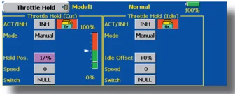
Note: At initial setting, the setting mode is the group mode. Since this function is not used at other conditions, switch to the single mode before setting.
●Setting to the state which activates the function The throttle hold function allows setting for throttle cut and switching of the function fixed at the idle position by switch for training. Either one or both functions can be performed.
●Hold position setting This function sets the servo operation position at throttle hold. (Throttle cut and idle positions)
●Other settings When you want to link operation with stick manipulation, the Auto mode can be set. When you want to adjust the servo speed, adjust [Speed].
- Pitch to RUD mixing setting Use this function when you want to suppress the torque generated by the changes in the pitch and speed of the main rotor during pitch operation. Adjust it so that the nose does not swing in the rudder direction. However, when using a heading hold gyro like those shown below, do not use Pitch to RUD mixing.
Note: When using a GY601, GY502, GY401, or other heading hold gyro, this Pitch to RUD mixing should not be used. The reaction torque is corrected at the gyro side. When operating the gyro in the AVCS mode, the mixed signal will cause neutral deviation symptoms and the gyro will not operate normally.
Call the Pitch to RUD mixing function from the Model Menu, and set the curve for each condition. (At initial setting, this function is in the "INH" state. To use it, set it to the "ON" state.)
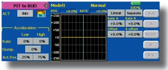
(17 points curve) Curve setting of up to 17 points is possible. However, in the following setting example, a simple curve can be adjusted by using the [Linear] curve type.
Note: At initial setting, the setting mode is the group mode. In this mode, the same contents are set at in all conditions. When you want to set the selected condition only, switch to the single mode.
<Model Basic Setting Procedure> 43
- A curve setting example is shown below. A. Pitch to RUD mixing curve (Normal) Use the hovering system and set this curve to match take off and landing and vertical climb at a constant speed.
*For this curve, use the initial setting [Linear] curve type and adjust the left and right rates in the [Separate] mode.
B. Pitch to RUD mixing (Idle up 1) Use this curve in 540° stall turn, loop, and rolling stall turn, and adjust it so the fuselage is facing straight ahead when heading into the wind.
*For this curve, [Linear] curve type can be used and the entire curve can be lowered with the [Offset] button.
C. Pitch to RUD mixing (Hold) This function is set so that the fuselage is facing straight ahead at straight line auto rotation. The pitch of the tail rotor becomes nearly 0°.
*For this curve, [Linear] curve type can be used and the entire curve can be lowered with the [Offset] button.
●Other settings The mixing rise characteristic at pitch operation can be adjusted. An acceleration (ACLR) function and deceleration (DCLR) function, which temporarily increase and decrease the mixing amount, can be set.
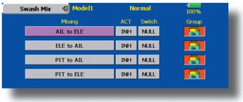
- Swash Mix corrects aileron, elevator and pitch interaction
The swash mix function is used to correct the swash plate in the aileron (roll) direction and elevator (cyclic pitch) corresponding to each operation of each condition.
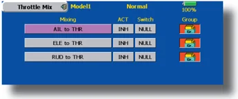
- Throttle mixing setting
RPM loss caused by swash operation at aileron or elevator operation can be corrected with the Throttle Mix function of the Model Menu. How clockwise and counterclockwise torque is applied when pirouetting can also be corrected.
- Gyro sensitivity and mode switching
The gyro sensitivity and mode switching function is dedicated gyro mixing of the Model Menu, and can be set for each condition.
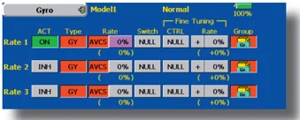
●Normal condition (hovering): Gyro sensitivity maximum ●Idle up 1/Idle up 2/Throttle hold: Gyro sensitivity minimum ●However, at auto rotation of a tail-driven helicopter, this function may not have any affect at high gyro sensitivity.
- Throttle cut setting
Throttle cut provides an easy way to stop the engine, by flipping a switch with the throttle stick at idle. The action is not functional at high throttle to avoid accidental dead sticks. The switch's location and direction must be chosen, as it defaults to NULL.
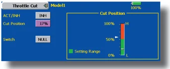
*With throttle stick at idle, adjust the cut position until the engine consistently shuts off, but throttle linkage is not binding. When finished, touch the "Throttle Cut" button to exit.
- Other special mixings ●Pitch to Needle mixing This mixing is used with engines with a construction which allows needle control during flight (fuel-air mixture adjustment). A needle curve can be set. The needle servo rise characteristics at throttle stick acceleration/deceleration operation can be adjusted. (Acceleration function) ●Fuel mixture function This mixing is used in needle adjustment of engines which use a fuel mixture control carburetor. ●Governor mixing This mixing is dedicated governor mixing when a GV-1 (governor) is used. Up to 3 rates (speeds) can be switched for each condition.
44 <Model Basic Setting Procedure>
Receiver and servos connection
Connect the receiver and servos in accordance with the connection diagram shown below. Always read [Precautions when mounting the receiver and servos] of [Before using]. When mounting the receiver and servos to the fuselage, connect the necessary points in accordance with the kit instruction manual.
Receiver and servos connection diagram
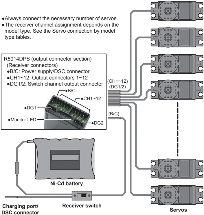
●Always connect the necessary number of servos. ●The receiver channel assignment depends on the model type. See the Servo connection by model type tables.
R5014DPS (output connector section)
(Receiver connectors)
●B/C: Power supply/DSC connector
●CH112: Output connectors 112
●DG1/2: Switch channel output connector
Ni-Cd battery
Charging port/ DSC connector
Receiver switch
Servos
●The Servo connection by model type tables are shown on the following pages. Connect the servos to match the fuselage used.
<Model Basic Setting Procedure> 45
Servo connection by model type
The T14MZ transmitter channels are automatically assigned for optimal combination according to the type selected with the Model Type function of the Linkage Menu. The channel assignment (initial setting) for each model type is shown below. Connect the receiver and servos to match the type used.
*The set channels can be checked at the Function screen of the Linkage Menu. The channel assignments can also be changed. For more information, read the description of the Function menu.
Airplane/glider/motor glider
●Airplane and V tail
| RX CH | 1AIL | 2AIL | 2AIL+1FLAP | 2AIL+2FLAP | ||||||||
|---|---|---|---|---|---|---|---|---|---|---|---|---|
| Airplane | Glider | Airplane | Glider | Airplane | Glider | Airplane | Glider | |||||
| EP | EP | EP | ||||||||||
| 1 | Elevator | Elevator | Elevator | Elevator | Elevator | Elevator | Elevator | Elevator | Elevator | |||
| 2 | Rudder | Rudder | Rudder | Rudder | Rudder | Rudder | Rudder | Rudder | Rudder | |||
| 3 | Throttle | Motor | AUX1 | Throttle | Motor | AUX1 | Throttle | Motor | AUX7 | Throttle | Motor | AUX6 |
| 4 | Aileron | Aileron | Aileron | Aileron | Aileron | Aileron | Aileron | Aileron | Aileron | |||
| 5 | Gear | AUX7 | AUX7 | Aileron2 | Aileron2 | Aileron2 | Aileron2 | Aileron2 | Aileron2 | |||
| 6 | Airbrake | Airbrake | Airbrake | Gear | AUX7 | AUX7 | Flap | Flap | Flap | Gear | AUX5 | AUX5 |
| 7 | AUX6 | AUX6 | AUX6 | AUX6 | AUX6 | AUX6 | Gear | AUX6 | AUX6 | Flap | Flap | Flap |
| 8 | AUX5 | AUX5 | AUX5 | AUX5 | AUX5 | AUX5 | AUX5 | AUX5 | AUX5 | Flap2 | Flap2 | Flap2 |
| 9 | AUX4 | AUX4 | AUX4 | AUX4 | AUX4 | AUX4 | AUX4 | AUX4 | AUX4 | AUX4 | AUX4 | AUX4 |
| 10 | AUX3 | AUX3 | AUX3 | AUX3 | AUX3 | AUX3 | AUX3 | AUX3 | AUX3 | AUX3 | AUX3 | AUX3 |
| 11 | AUX2 | AUX2 | AUX2 | AUX2 | AUX2 | AUX2 | AUX2 | AUX2 | AUX2 | AUX2 | AUX2 | AUX2 |
| 12 | AUX1 | AUX1 | AUX1 | AUX1 | AUX1 | AUX1 | AUX1 | AUX1 | AUX1 | AUX1 | AUX1 | AUX1 |
| VC1 | AUX1 | AUX1 | AUX1 | Camber | Camber | Camber | Camber | Camber | Camber | Camber | Camber | Camber |
| VC2 | AUX1 | AUX1 | AUX1 | AUX1 | Butterfly | Butterfly | AUX1 | Butterfly | Butterfly | AUX1 | Butterfly | Butterfly |
| VC3 | AUX1 | AUX1 | AUX1 | AUX1 | AUX1 | AUX1 | AUX1 | AUX1 | AUX1 | AUX1 | AUX1 | AUX1 |
| VC4 | AUX1 | AUX1 | AUX1 | AUX1 | AUX1 | AUX1 | AUX1 | AUX1 | AUX1 | AUX1 | AUX1 | AUX1 |
●When a receiver other than the PCM-G3 type is used, only the shaded part of the table above is valid.
●VC1~4 are vertical channels without receiver output. For more information, see the description of the Function menu of the Linkage Menu.
| RX CH | 2AIL+4FLAP | 4AIL+2FLAP | 4AIL+4FLAP | ||||||
|---|---|---|---|---|---|---|---|---|---|
| Airplane | Glider | Airplane | Glider | Airplane | Glider | ||||
| EP | EP | EP | |||||||
| 1 | Elevator | Elevator | Elevator | Elevator | Elevator | Elevator | Elevator | Elevator | Elevator |
| 2 | Rudder | Rudder | Rudder | Rudder | Rudder | Rudder | Rudder | Rudder | Rudder |
| 3 | Throttle | Motor | AUX4 | Throttle | Motor | AUX4 | Throttle | Motor | AUX2 |
| 4 | Aileron | Aileron | Aileron | Aileron | Aileron | Aileron | Aileron | Aileron | Aileron |
| 5 | Aileron2 | Aileron2 | Aileron2 | Aileron2 | Aileron2 | Aileron2 | Aileron2 | Aileron2 | Aileron2 |
| 6 | Gear | AUX3 | AUX3 | Gear | AUX3 | AUX3 | Gear | AUX1 | AUX1 |
| 7 | Flap | Flap | Flap | Aileron3 | Aileron3 | Aileron3 | Aileron3 | Aileron3 | Aileron3 |
| 8 | Flap2 | Flap2 | Flap2 | Aileron4 | Aileron4 | Aileron4 | Aileron4 | Aileron4 | Aileron4 |
| 9 | Flap3 | Flap3 | Flap3 | Flap1 | Flap1 | Flap1 | Flap1 | Flap1 | Flap1 |
| 10 | Flap4 | Flap4 | Flap4 | Flap2 | Flap2 | Flap2 | Flap2 | Flap2 | Flap2 |
| 11 | AUX2 | AUX2 | AUX2 | AUX2 | AUX2 | AUX2 | Flap3 | Flap3 | Flap3 |
| 12 | AUX1 | AUX1 | AUX1 | AUX1 | AUX1 | AUX1 | Flap4 | Flap4 | Flap4 |
| VC1 | Camber | Camber | Camber | Camber | Camber | Camber | Camber | Camber | Camber |
| VC2 | AUX1 | Butterfly | Butterfly | AUX1 | Butterfly | Butterfly | AUX1 | Butterfly | Butterfly |
| VC3 | AUX1 | AUX1 | AUX1 | AUX1 | AUX1 | AUX1 | AUX1 | AUX1 | AUX1 |
| VC4 | AUX1 | AUX1 | AUX1 | AUX1 | AUX1 | AUX1 | AUX1 | AUX1 | AUX1 |
46 <Model Basic Setting Procedure>
●Ailevator
| RX CH | 1AIL | 2AIL | 2AIL+1FLAP | 2AIL+2FLAP | |||||
|---|---|---|---|---|---|---|---|---|---|
| Airplane | Glider | Airplane | Glider | Airplane | Glider | Airplane | Glider | ||
| EP | EP | EP | |||||||
| 1 | Elevator | Elevator | Elevator | Elevator | Elevator | Elevator | Elevator | Elevator | Elevator |
| 2 | Elevator2 | Elevator2 | Elevator2 | Elevator2 | Elevator2 | Elevator2 | Elevator2 | Elevator2 | Elevator2 |
| 3 | Rudder | Rudder | Rudder | Rudder | Rudder | Rudder | Rudder | Rudder | Rudder |
| 4 | Aileron | Aileron | Aileron | Aileron | Aileron | Aileron | Aileron | Aileron | Aileron |
| 5 | Throttle | Motor | AUX7 | Aileron2 | Aileron2 | Aileron2 | Aileron2 | Aileron2 | Aileron2 |
| 6 | Airbrake | Airbrake | Airbrake | Throttle | Motor | AUX7 | Throttle | Motor | AUX6 |
| 7 | Gear | AUX6 | AUX6 | Gear | AUX6 | AUX6 | Flap | Flap | Flap |
| 8 | AUX5 | AUX5 | AUX5 | AUX5 | AUX5 | AUX5 | Gear | AUX5 | AUX5 |
| 9 | AUX4 | AUX4 | AUX4 | AUX4 | AUX4 | AUX4 | AUX4 | AUX4 | AUX4 |
| 10 | AUX3 | AUX3 | AUX3 | AUX3 | AUX3 | AUX3 | AUX3 | AUX3 | AUX3 |
| 11 | AUX2 | AUX2 | AUX2 | AUX2 | AUX2 | AUX2 | AUX2 | AUX2 | AUX2 |
| 12 | AUX1 | AUX1 | AUX1 | AUX1 | AUX1 | AUX1 | AUX1 | AUX1 | AUX1 |
| VC1 | AUX1 | AUX1 | AUX1 | Camber | Camber | Camber | Camber | Camber | Camber |
| VC2 | AUX1 | AUX1 | AUX1 | AUX1 | Butterfly | Butterfly | AUX1 | Butterfly | Butterfly |
| VC3 | AUX1 | AUX1 | AUX1 | AUX1 | AUX1 | AUX1 | AUX1 | AUX1 | AUX1 |
| VC4 | AUX1 | AUX1 | AUX1 | AUX1 | AUX1 | AUX1 | AUX1 | AUX1 | AUX1 |
●When a receiver other than the PCM-G3 type is used, only the shaded part of the table above is valid.
●VC1~4 are vertical channels without a receiver output. For more information, see the description of the Function menu of the Linkage Menu.
| RX CH | 2AIL+4FLAP | 4AIL+2FLAP | 4AIL+4FLAP | ||||||
|---|---|---|---|---|---|---|---|---|---|
| Airplane | Glider | Airplane | Glider | Airplane | Glider | ||||
| EP | EP | ||||||||
| 1 | Elevator | Elevator | Elevator | Elevator | Elevator | Elevator | Elevator | ||
| 2 | Elevator2 | Elevator2 | Elevator2 | Elevator2 | Elevator2 | Elevator2 | Elevator2 | ||
| 3 | Rudder | Rudder | Rudder | Rudder | Rudder | Rudder | Rudder | ||
| 4 | Aileron | Aileron | Aileron | Aileron | Aileron | Aileron | Aileron | ||
| 5 | Aileron2 | Aileron2 | Aileron2 | Aileron2 | Aileron2 | Aileron2 | Aileron2 | ||
| 6 | Throttle | Motor | AUX7 | Throttle | Motor | AUX3 | Throttle | Motor | AUX1 |
| 7 | Flap | Flap | Flap | Aileron3 | Aileron3 | Aileron3 | Aileron3 | Aileron3 | Aileron3 |
| 8 | Flap2 | Flap2 | Flap2 | Aileron4 | Aileron4 | Aileron4 | Aileron4 | Aileron4 | Aileron4 |
| 9 | Flap3 | Flap3 | Flap3 | Flap1 | Flap1 | Flap1 | Flap1 | Flap1 | Flap1 |
| 10 | Flap4 | Flap4 | Flap4 | Flap2 | Flap2 | Flap2 | Flap2 | Flap2 | Flap2 |
| 11 | Gear | AUX2 | AUX2 | Gear | AUX2 | AUX2 | Flap3 | Flap3 | Flap3 |
| 12 | AUX1 | AUX1 | AUX1 | AUX1 | AUX1 | AUX1 | Flap4 | Flap4 | Flap4 |
| VC1 | Camber | Camber | Camber | Camber | Camber | Camber | Camber | Camber | Camber |
| VC2 | AUX1 | Butterfly | Butterfly | AUX1 | Butterfly | Butterfly | AUX1 | Butterfly | Butterfly |
| VC3 | AUX1 | AUX1 | AUX1 | AUX1 | AUX1 | AUX1 | AUX1 | AUX1 | AUX1 |
| VC4 | AUX1 | AUX1 | AUX1 | AUX1 | AUX1 | AUX1 | AUX1 | AUX1 | AUX1 |
<Model Basic Setting Procedure> 47
Tailless wing
| RX CH | 2AIL | 2AIL+1FLAP | 2AIL+2FLAP | ||||||
|---|---|---|---|---|---|---|---|---|---|
| Airplane | Glider | Airplane | Glider | Airplane | Glider | ||||
| EP | EP | EP | |||||||
| 1 | Rudder | Rudder | Rudder | Rudder | Rudder | Rudder | Rudder | Rudder | Rudder |
| 2 | Rudder2 | Rudder2 | Rudder2 | Rudder2 | Rudder2 | Rudder2 | Rudder2 | Rudder2 | Rudder2 |
| 3 | Throttle | Motor | AUX1 | Throttle | Motor | AUX7 | Throttle | Motor | AUX6 |
| 4 | Aileron | Aileron | Aileron | Aileron | Aileron | Aileron | Aileron | Aileron | Aileron |
| 5 | Aileron2 | Aileron2 | Aileron2 | Aileron2 | Aileron2 | Aileron2 | Aileron2 | Aileron2 | Aileron2 |
| 6 | Gear | AUX7 | AUX7 | Flap | Flap | Flap | Gear | AUX5 | AUX5 |
| 7 | AUX6 | AUX6 | AUX6 | Gear | AUX6 | AUX6 | Flap | Flap | Flap |
| 8 | AUX5 | AUX5 | AUX5 | AUX5 | AUX5 | AUX5 | Flap2 | Flap2 | Flap2 |
| 9 | AUX4 | AUX4 | AUX4 | AUX4 | AUX4 | AUX4 | AUX4 | AUX4 | AUX4 |
| 10 | AUX3 | AUX3 | AUX3 | AUX3 | AUX3 | AUX3 | AUX3 | AUX3 | AUX3 |
| 11 | AUX2 | AUX2 | AUX2 | AUX2 | AUX2 | AUX2 | AUX2 | AUX2 | AUX2 |
| 12 | AUX1 | AUX1 | AUX1 | AUX1 | AUX1 | AUX1 | AUX1 | AUX1 | AUX1 |
| VC1 | Elevator | Elevator | Elevator | Elevator | Elevator | Elevator | Elevator | Elevator | Elevator |
| VC2 | AUX1 | AUX1 | AUX1 | Camber | Camber | Camber | Camber | Camber | Camber |
| VC3 | AUX1 | AUX1 | AUX1 | AUX1 | Butterfly | Butterfly | AUX1 | Butterfly | Butterfly |
| VC4 | AUX1 | AUX1 | AUX1 | AUX1 | AUX1 | AUX1 | AUX1 | AUX1 | AUX1 |
- When a receiver other than the PCM-G3 type is used, only the shaded part of the table above is valid.
- VC1~4 are virtual channels without a receiver output. For more information, see the description of the Function menu of the Linkage Menu.
| RX CH | 2AIL+4FLAP | 4AIL+2FLAP | 4AIL+4FLAP | ||||||
|---|---|---|---|---|---|---|---|---|---|
| Airplane | Glider | Airplane | Glider | Airplane | Glider | ||||
| EP | EP | EP | |||||||
| 1 | Rudder | Rudder | Rudder | Rudder | Rudder | Rudder | Rudder | Rudder | Rudder |
| 2 | Rudder2 | Rudder2 | Rudder2 | Rudder2 | Rudder2 | Rudder2 | Rudder2 | Rudder2 | Rudder2 |
| 3 | Throttle | Motor | AUX4 | Throttle | Motor | AUX4 | Throttle | Motor | AUX2 |
| 4 | Aileron | Aileron | Aileron | Aileron | Aileron | Aileron | Aileron | Aileron | Aileron |
| 5 | Aileron2 | Aileron2 | Aileron2 | Aileron2 | Aileron2 | Aileron2 | Aileron2 | Aileron2 | Aileron2 |
| 6 | Gear | AUX3 | AUX3 | Gear | AUX3 | AUX3 | Gear | AUX1 | AUX1 |
| 7 | Flap | Flap | Flap | Aileron3 | Aileron3 | Aileron3 | Aileron3 | Aileron3 | Aileron3 |
| 8 | Flap2 | Flap2 | Flap2 | Aileron4 | Aileron4 | Aileron4 | Aileron4 | Aileron4 | Aileron4 |
| 9 | Flap3 | Flap3 | Flap3 | Flap1 | Flap1 | Flap1 | Flap1 | Flap1 | Flap1 |
| 10 | Flap4 | Flap4 | Flap4 | Flap2 | Flap2 | Flap2 | Flap2 | Flap2 | Flap2 |
| 11 | AUX2 | AUX2 | AUX2 | AUX2 | AUX2 | AUX2 | Flap3 | Flap3 | Flap3 |
| 12 | AUX1 | AUX1 | AUX1 | AUX1 | AUX1 | AUX1 | Flap4 | Flap4 | Flap4 |
| VC1 | Elevator | Elevator | Elevator | Elevator | Elevator | Elevator | Elevator | Elevator | Elevator |
| VC2 | Camber | Camber | Camber | Camber | Camber | Camber | Camber | Camber | Camber |
| VC3 | AUX1 | Butterfly | Butterfly | AUX1 | Butterfly | Butterfly | AUX1 | Butterfly | Butterfly |
| VC4 | AUX1 | AUX1 | AUX1 | AUX1 | AUX1 | AUX1 | AUX1 | AUX1 | AUX1 |
48 <Model Basic Setting Procedure>
Helicopter
| CH | H-4 Swash | All Other |
|---|---|---|
| 1 | Throttle | Throttle |
| 2 | Rudder | Rudder |
| 3 | Aileron | Gyro |
| 4 | Elevator 1 | Aileron |
| 5 | Pitch | Elevator |
| 6 | Elevator 2 | Pitch |
| 7 | Gyro | Governor 1 |
| 8 | Governor 1 | Governor 2 |
| 9 | Governor 2 | Needle |
| 10 | Needle | AUX3 |
| 11 | AUX2 | AUX2 |
| 12 | AUX1 | AUX1 |
| VC1 | AUX1 | AUX1 |
| VC2 | AUX1 | AUX1 |
| VC3 | AUX1 | AUX1 |
| VC4 | AUX1 | AUX1 |
- When a receiver other than the PCM-G3 type is used, only the shaded part of the table at the left is valid.
- VC1~4 are virtual channels with no receiver output. For more information, see the description of the Function menu of the Linkage Menu.
<Model Basic Setting Procedure> 49
FUNCTIONS OF LINKAGE MENU
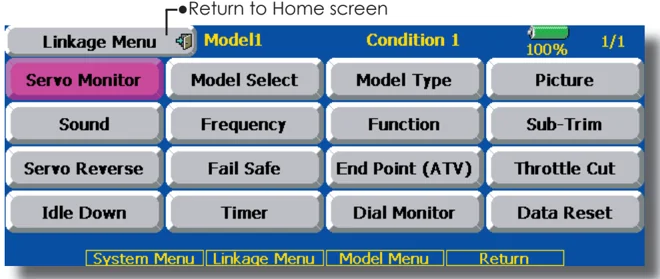
The Linkage Menu is made up of functions which perform model addition, model type selection, frequency setting, end point setting, and other model basic settings.
The functions which can be selected depend on the model type. A typical menu screen is shown below.
• When a button in the Linkage Menu of the Home screen is touched, the menu shown below is called. Touch the button of the function you want to set.
Return to Home screen
(The display screen is an example. The screen depends on the model type.)
Linkage Menu functions table
[Servo Monitor]: Displays the servo test and operation position [Model Select]: Model addition, call, deletion, copy, model name setting [Model Type]: Model type, wing type, switch type, etc. selection [Picture]: Picture paste for each model [Sound]: Sound recording and playback [Frequency]: Frequency selection, modulation mode selection, receiver ID setting [Function]: Channel assignment of each function can be changed [Sub-Trim]: Adjusts the neutral position of each servo [Servo Reverse]: Servo direction reversal [Fail Safe]: Fail safe function and battery fail safe function setting [End Point (ATV)]: Servo basic rudder adjustment and limit setting [Throttle Cut]: Stops the engine safely and easily (airplane and helicopter only) [Idle Down]: Lowers the idle speed of the engine (airplane and helicopter only) [Swash]: Swash AFR and linkage correction function (helicopter only) [Timer]: Timer setting and lap time display [Dial Monitor]: Dial, sliding lever, and digital trim position display [Data Reset]: Model memory set data reset (by item)
50 <Linkage Menu>