Servo Monitor
Servo Test & Graph Display / Displays servo positions.
This is used for testing servo movement. Touch “Moving Test” (repetition mode) or “Neutral Test” (fixed position mode) depending on which one shows on the screen. To get from one to the other, simply touch the field again, and you will move from “Moving Test” to “Neutral Test” automatically. Next touch the “Test” on/off button to start testing your servos. The “Neutral test” is good for finding the neutral position of a servo horn.
- Touch the [Servo Monitor] button in the Linkage Menu to call the setup screen shown below.
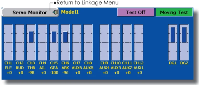
Servo test operation
- Select a test mode ([Moving] or [Neutral]). [Repeat]: Each servo repeats operation. [Neutral]: Each servo is locked in the neutral position.
- When the [Test Off] button is touched, testing begins in the selected mode.
<Linkage Menu> 51
Model Select
The Model Selection function performs model addition, call, deletion, copy, and model name setting.
This function is used to load the settings of the desired model into the T14MZ's memory.
The settings may be selected from either the transmitter's built-in memory or a Data-Pack CFDP32M (Compact Flash card; 32MB). Remember that up to 30 model memories are available in the transmitter; these may be stored in the CFDP32M card.
The name of the model stored in the transmitter and the Data-Pack may be changed. This can be very useful to tell different models settings apart. Each model name can be as long as 32 characters, and the model name always appears in the display screen.
The Copy function is used to copy one set of model data into a second memory within the transmitter and the Data-Pack. It may be used for getting a head-start on setting up models with almost the same settings (only differences need to be modified, instead of entering the complete model from scratch). Also, this function may be used to make a backup copy of a model setup before any changes are made.
• Touch the [Model Select] button in the Linkage Menu to call the setup screen shown below.
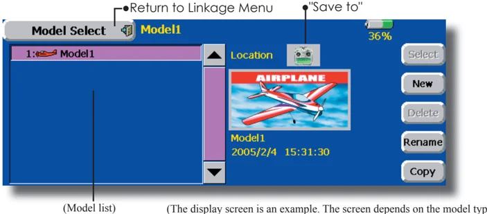
(Model list) (The display screen is an example. The screen depends on the model type.)
Model call
- Touch the "Save to" icon, and select the location to which the desired model is to be saved. Transmitter icon: Transmitter memory Data pack icon: CF card
- Touch the desired model in the model list.
- Touch the [Select] button.
- Touch [Yes] to call the model. (When you want to cancel model call, press [No].)
Model addition
- Touch the [New] button.
- Touch [Yes] to add the model. (When you want to cancel model addition, touch [No].) *When a new model is added, the Model Type screen and Frequency screen are automatically displayed. Check or change the model and frequency. If there are no changes, touch the Model Type and Frequency icons. *The added model is displayed in the model list.
Model deletion
- Touch the "Save to" icon or the model you want to delete in the model list. (The model currently selected cannot be deleted.)
- Touch the [Delete] button.
- Touch [Yes]. (When you want to stop model deletion, touch [No].)
Model name change
- Select the model by touching the "Save to" icon or the desired model in the model list.
- When [Change Name] is touched, a keyboard appears on the screen.
- Enter the model name from this keyboard. *Up to 32 characters can be input at the model name. Japanese language input is also possible. (For a detailed description of the input method, see "User Name Registration/Character Input Method" of the Basic Operation section.
Model copy
- Touch the [Copy] button to call the Copy screen.
- Touch the "Source" button and select the model to be copied.
- Touch the "Destination" button and select the copy storage destination. (Transmitter or CF card)
- Touch the center [Copy] button.
- When [Yes] is touched, copying is executed. (When you want to cancel copying, touch [No].) *If there is no model of the same name at the copy destination, the name of the copy source is saved. If there is a model of the same name, a number is appended to the end of the model name and the model is copied. Change the name later.
52 <Linkage Menu>
Model Type
This function selects the model type from among airplane, helicopter, and glider.
Seven types of main wings and three types of tail wings are available for airplanes. Seven swash types are available for helicopters. Seven types of main wings and three types of tail wings are available for gliders. Functions and mixing functions necessary for each model type are set in advance at the factory.
Note: The Model Type function automatically selects the appropriate output channels, control functions, and mixing functions for the chosen model type. When the Model Type Selection command is accessed, all of the data in the active memory is cleared. Be sure that you don't mind losing this data, or back it up to another memory using the copying functions.
- Touch the [Model Type] button in the Linkage Menu to call the setup screen shown below.
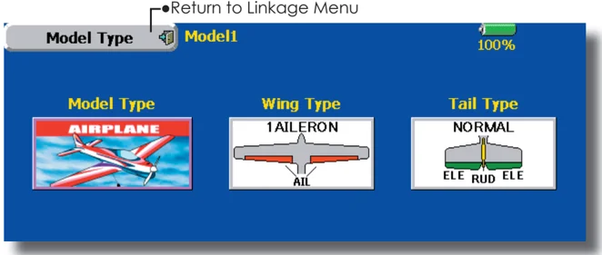
(The display screen is an example. The screen depends on the model type.)
Model type selection
- Call the Type select screen by touching the model type, wing, tail, swash type, or other type button.
- Select the type you want to set, and execute type selection by touching [Yes] at the confirmation screen. (When you want to cancel model type selection, touch [No].)
<Linkage Menu> 53
•Model type selection
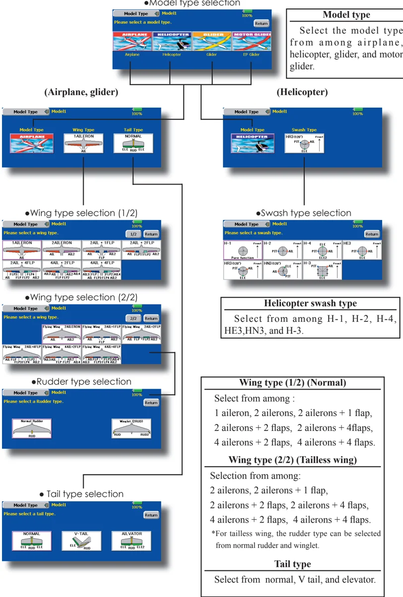
Model type Select the model type from among airplane, helicopter, glider, and motor glider.
(Airplane, glider)
(Helicopter)
•Wing type selection (1/2)
•Swash type selection
Helicopter swash type Select from among H-1, H-2, H-4, HE3, HN3, and H-3.
•Wing type selection (2/2)
Wing type (1/2) (Normal) Select from among : 1 aileron, 2 ailerons, 2 ailerons + 1 flap, 2 ailerons + 2 flaps, 2 ailerons + 4flaps, 4 ailerons + 2 flaps, 4 ailerons + 4 flaps.
Wing type (2/2) (Tailless wing) Selection from among: 2 ailerons, 2 ailerons + 1 flap, 2 ailerons + 2 flaps, 2 ailerons + 4 flaps, 4 ailerons + 2 flaps, 4 ailerons + 4 flaps. *For tailless wing, the rudder type can be selected from normal rudder and winglet.
•Rudder type selection
Tail type Select from normal, V tail, and elevator.
•Tail type selection
54 <Linkage Menu>
Picture
A picture can be pasted for each model. (Simplifies identification of the model data during screen operation.)
A photograph of the model taken with a digital camera or other file can be pasted as the screen display data for each model. This is convenient in identifying models with the same model name.
*The picture files which can be displayed on the screen are size 168 x 80 pixels, file type .bmp (bit map picture) files. If a file larger than this is pasted, the top left-hand side of the picture is displayed.
*Paste the picture after saving the picture data from your PC to the accessory CF card and inserting the CF card into the transmitter.
When a picture is pasted, it is displayed as the following screen image: •Model Select screen •Home screen •Startup screen
• Touch the [Picture] button in the Linkage Menu to call the setup screen shown below.
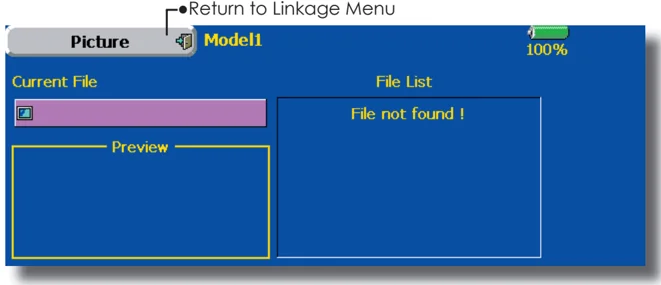
Pasting of picture
*Picture data is pasted to the model memory currently in use.
- Select the picture from the file list by touching the desired picture data.
*Before selection, touch the scroll button at the top or bottom of the file list and confirm the contents of the picture files saved on the CF card at the preview screen.
- To paste the picture, touch [Yes]. (When you want to cancel pasting, touch [No].)
[Important]
Before reading data from the PC, insert the CF card into the transmitter and turn on the power. The following folders are automatically written. To read a file from the PC, copy the file to a folder by file type.
•BMP: Picture file •WMA: Music file •WAV: Audio file •MODEL: Model data
<Linkage Menu> 55
Sound
Sound recording and playback.
Sounds recorded with the microphone built into the transmitter and audio files (.wav) saved on the CF card from the PC can be played back when the power switch is turned on and off or by preset switch.
*The recording time from the microphone is up to 3 seconds/ recording. Twenty-four audio files can be saved. *When recording, insert the CF card into the transmitter. *The only audio file type which can be recorded is .wav. Only the sounds recorded with the built-in microphone or an audio file saved from your PC to the data pack can be played back.
Setup screens No. 3 to 24 can be individually assigned to audio file switches, etc. The playback files can be switched each time the same switch is operated. This can be used when playing back the name of maneuvers, etc.
[Sound starting] No. 1: When transmitter power switch turned on No. 2: When transmitter power switch turned off No. 3~24: Switch can be set.
[Important] Before reading data from a PC, insert the CF card into the transmitter and turn on the power. The following folders are automatically written. When reading a file from the PC, copy it to a holder by file type. ●BMP: Picture file ●WMA: Music file ●WAV: Audio file ●MODEL: Model data
● Touch the [Sound] button in the Linkage Menu to call the setup screen shown below.
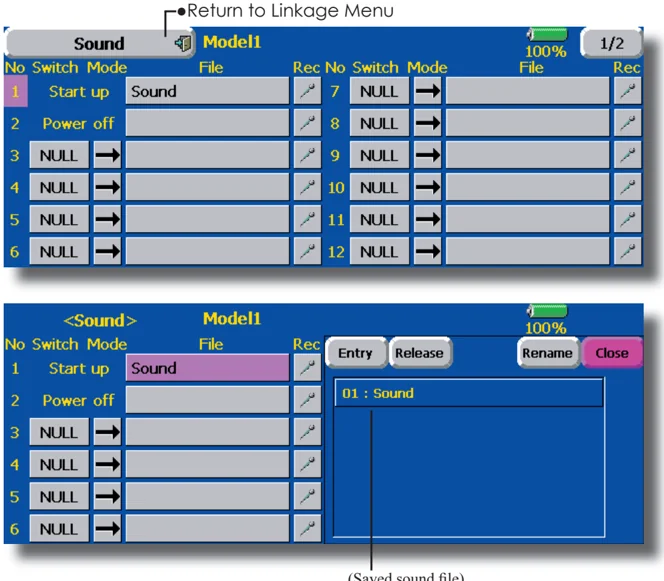
Return to Linkage Menu
(Saved sound file)
Voice Recording
- Touch any REC button to call up the SOUND RECORDER screen.
- Touch the REC button to start recording. (Recording time: 3 seconds)
- Record your voice as you are facing the transmitter's microphone.
- To finish, press "CLOSE". (The voice file is stored in the Data-Pack automatically.)
Also sound files created by your PC may be played back by assigned switches. (File types; .wav file only) *You can only assign a sound data stored from your PC to a Data-Pack.
56 <Linkage Menu>
Assignment of audio files to switches
*Audio files can be saved to CF card beforehand.
- Touch the file button of the No. you want to set. A list of the files stored on the CF card is displayed.
- Select the audio file you want to play back from the list of audio files.
*Since the audio files are played back when the audio file names in the list are touched, the file contents can be checked before assignment.
-
Touch the [File] button to assign the files.
-
(Switches are also selected for No. 3~24.) Touch the [NULL] button to call the Switch select screen.
-
Select the switch and its ON direction at the Switch select screen. (For a detailed description of the selection method, see "Switch setting method" at the back of this manual.)
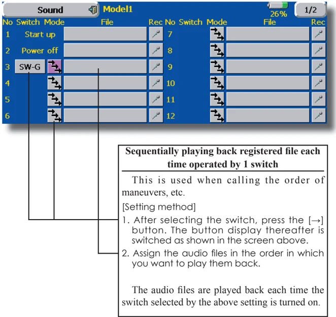
Sequentially playing back registered file each time operated by 1 switch
This is used when calling the order of maneuvers, etc.
[Setting method]
- After selecting the switch, press the [→] button. The button display thereafter is switched as shown in the screen above.
- Assign the audio files in the order in which you want to play them back.
The audio files are played back each time the switch selected by the above setting is turned on.
<Linkage Menu> 57
Frequency
Frequency Band (frequency) setting, modulation mode setting, receiver ID code setting.
Frequency setting
The T14MZ transmitter uses a synthesizer system. Its frequency can be changed within the range of the frequency band of the module used. The frequency of the R5014DPS receiver is set from the transmitter. Use a receiver matched to the frequency band of the transmitter.
Receiver ID code
When the R5014DPS receiver (PCM-G3 receiver) is used, the ID code located on the back of the receiver case must be entered. *When two receivers are used with a large model, etc., enter the 2nd receiver ID also. • Touch the [Frequency] button in the Linkage Menu to call the setup screen shown below.
 Return to Linkage Menu
Frequency Model1 100%
Band No. (Freq. CH) 11 (72.010 MHz)
Frequency Band 72MHz
Area America
Modulation PCM-G3
Receiver ID 00001001
2nd Receiver ID No Use
Modulation mode selection
With the T14MZ, 3 modulation modes (PCM-G3/ PCM1024/PPM (FM)) can be selected. Select the modulation mode matched to the type of receiver used. *After changing the modulation mode, switch the modulation mode by turning the transmitter power off and on.
Frequency switching method
For a description of the frequency switching and ID setting methods, refer to the procedure given in the Basic Operation section.
Modulation mode change
- Touch the Modulation Mode button to call the selection screen, and then touch the button of the type of modulation used.
- Touch the [Enter] button to switch the mode. *When switching from the PCM-G3 mode to another mode, the mode cannot be switched if the number of channels is insufficient due to the wing type used.
- After switching the modulation mode, turn the transmitter power off and then switch the mode by turning the transmitter power back on.
Receiver ID code input
- Touch the receiver ID No. on the screen. The receiver ID setup screen is displayed. Input the 8-digit ID number displayed on the back case of the receiver.
- If the ID number is correct, touch the [Enter] button. To correct the number, use the [BS] button and change the number to the correct ID code. *Once the ID code is set, it does not have to be set again as long as the receiver is not changed.
⚠ WARNING
! When flying after frequency change, emit radio waves only after verifying the frequency. *Also change the frequency clip. Emitting radio waves without verification is extremely dangerous.
58 <Linkage Menu>
Function
Channel assignment of each function can be changed.
When you select model and wing (swash) types, you will find that the optimized combinations of servo output channels and functions have been already preset. If you would like, on the function-setting screen of the linkage menu, you can freely change combinations of servo output channels, functions (aileron, elevator, etc), and input controllers (sticks, switches, trim levers and trim switches). You can also assign the same function to multiple servo output channels such as assigning elevator function to CH2 and CH3.
DG1, DG2 (switch channels) These two channels can be used as switch channels. You can freely change combinations between servo output channels and input controllers (sticks, switches, trim levers and trim switches).
VC1~VC4 (virtual channels) These four channels can be set as virtual functions that do not have servo output channels. You can freely change combinations between functions (aileron, elevator, etc) and input controllers (sticks, switches, trim levers and trim switches).
Note: In PCMG3 mode, combinations of three channels such as CH 1 through CH 3, CH 4 through CH 6, CH 7through CH 9 and CH 10 through CH 12 work simultaneously. Futaba recommends that you use the standard optimized default combinations of channels and functions in order to minimize servo delay when you use multiple servos to control models such as swash mode helicopters and dual elevator airplanes or flaperon airplanes.
Servo Output Channels For PCMG3 mode, you can set twelve linear channels and two digital channels. For PCM1024 mode, you can set eight linear channels and one digital channel. For PPM mode, you can set only eight linear channels.
- Touch the [Function] button in the Linkage Menu to call the setup screen shown below.
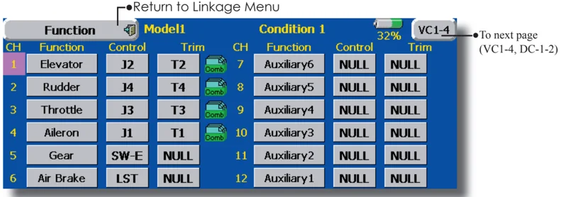
Return to Linkage Menu To next page (VC1-4, DC-1-2)
(The display screen is an example. The screen depends on the model type.)
Function change
- Touch the function button of the channel you want to change to call the function list.
- Select the function you want to change.
- Touch [Yes]. The display returns to the original screen. (When you want to cancel function change, touch [No].) *Multiple channels can be assigned to 1 function.
Operation control change
- Touch the control button of the channel you want to change. A Control select screen (stick, switch, knob, trim lever, etc.) is displayed.
- Select the control you want to operate.
- Touch [Close]. The display returns to the preceding screen. *The same control can be assigned to multiple channels.
<Linkage Menu> 59
Trim change
- Touch the Trim button to call the Trim setup screen.
- The following items can be set at the Trim setup screen.
- Hardware setting (Selection of switch, etc. which controls trim) (The select screen is called by touching the [H/W Select] button.)
- Rate setting
- Operation step setting
- Trim mode setting Normal mode: Normal trim (parallel shift trim) operation
ATL mode: ATL operation mode. Reverse is also possible. CTRM mode: Maximum change near center by center trim operation
- Separate/combination mode: Trim data are set to flight conditions Separate mode: Trim adjustment for each flight condition
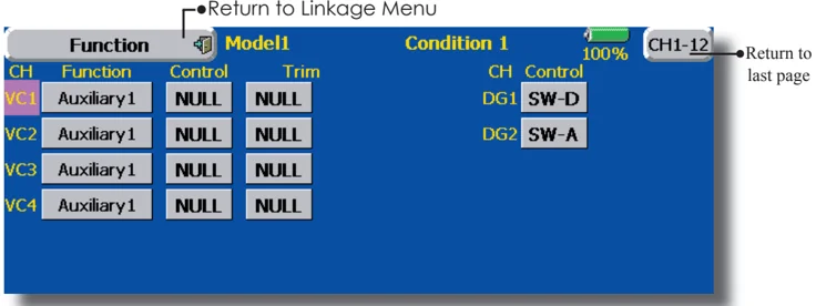
Return to Linkage Menu
Return to last page
(The display screen is an example. The screen depends on the model type.)
60 <Linkage Menu>
Sub-Trim Setting of neutral position of each servo.
The Sub-Trim function is used to set the servo neutral position, and may be used to make fine adjustments to the control surface after linkages and pushrods are hooked up. When you begin to set up a model, be sure that the digital trims are set to their center position.
• Touch the [Sub Trim] button in the Linkage Menu to call the setup screen shown below.
 Return to Linkage Menu
Sub-Trim Model1 100%
+0 +0 +0 +0 +0 +0 +0 +0 +0 +0 +0 +0
CH1 CH2 CH3 CH4 CH5 CH6 CH7 CH8 CH9 CH10 CH11 CH12
ELE RUD THR AIL GEA ABK AUX6 AUX5 AUX4 AUX3 AUX2 AUX1
(The display screen is an example. The screen depends on the model type.)
Sub trim adjustment
- Touch the trim display part of the channel you want to adjust. Adjustment buttons appears on the Sub Trim menu screen.
- Use the adjustment buttons to adjust the sub trim. • Initial value: 0 • Adjustment range: -240~+240 (steps) *See above
- Repeat this step for each channel.
<Linkage Menu> 61
Servo Reverse
Use to reverse the throw direction.
Servo Reverse changes the direction of an individual servo’s response to a control stick movement.
For CCPM helicopters, be sure to read the section on Swash AFR before reversing any servos. With CCPM helicopters, always complete your servo reversing prior to any other programming. If you use pre-built Airplane/Sailplane functions that control multiple servos, it may be confusing to tell whether the servo needs to be reversed or a setting in the function needs to be reversed. See the instructions for each specialized function for further details. Always check servo direction prior to every flight as an additional precaution to confirm proper model memory, hook ups, and radio function.
• Touch the [Servo Reverse] button in the Linkage Menu to call the setup screen shown below.
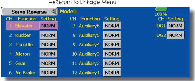
(The display screen is an example. The screen depends on the model type.)
Servo reversing procedure
After setting up a new model, be sure to define all special menus. Be sure that all servos are plugged into the proper receiver channels. Now, determine whether you need to reverse any channels by moving each stick and observing the corresponding movement in the model’s controls.
- Touch the desired channel’s Setting button to choose the proper direction for the servo
- Touch “Yes” in the next screen.
- Repeat for each servo needing reversal. When done, touch “Servo Reverse” to return to the Linkage Menu.
62 <Linkage Menu>
Fail Safe
Sets the servos operating position when transmitter signals can no longer be received or when the receiver battery voltage drops.
The Failsafe function may be used to set up positions that the servos move to in the case of radio interference.
This function only works with G3 or PCM receivers (FM receivers do not have failsafe capability).
When the receiver battery voltage drops, the servo can be moved to a preset position. (Battery fail safe function) A battery fail safe function reset switch can be set. (Initial setting: Throttle stick maximum slow side)
You may set either of two positions for each channel: Hold, where the servo maintains its last commanded position, or Failsafe, where each servo moves to a predetermined position. You may choose either mode for each channel.
The T14MZ system also provides you with an advanced battery monitoring function that warns you when the receiver battery has only a little power remaining. In this case, each servo is moved to the defined failsafe position. The battery
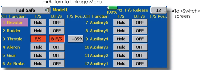
- Touch the [Fail Safe] button in the Linkage Menu to call the setup screen shown below.

(The display screen is an example. The screen depends on the model type.)
Fail safe setting procedure
Decide which channels you want to go to preset positions, and which ones you want to maintain their last commanded position. To select the failsafe mode you wish to set, use the F/S button. This button toggles between the two modes. (Hold, F/S)
F/S mode setting:
- Touch the F/S button of the channel you want to set, and set that channel to the [F/S] mode.
- Hold the corresponding stick, control, slider, or other control in the position you want the servo to move to when the fail safe function is activated, and touch the F/S position button. That position is displayed in percentage.
*When you want to return that channel to the Hold mode, touch the [F/S] button again.
Battery fail safe setting procedure
To select the B.F/S mode, touch the [B.F/S] button. Each time the button is touched, it toggles between [OFF] and [B.F/S].
B.F/S setting:
- Touch the [B.F/S] button of the desired channel to set it to the B.F/S mode.
- Hold the corresponding stick, VR, slider, or other control in the position you want the servo to move to when the battery fail safe function is activated, and touch the F/S position button. This position is displayed in percentage.
*When you want to return that channel to OFF, touch the [B.F/S] button again.
Battery Failsafe Release Function
This function releases the predefined control from it's held position after indicating that your receiver battery is low.
- Enter the control setting screen by touching the Battery F/S Release button. Now, you may choose that moving the throttle resets the condition, or select another stick or switch deactivates it. To set a desired throttle release position, move the throttle stick to the point at which you wish the B.F/S to be released.
failsafe may be released by operating a predefined control on the transmitter (default is throttle), do not continue to fly, land as soon as possible. Remember, if the predefined control suddenly moves to a position you did not command, land at once and check your receiver battery.
Defines servo position when signals are lost and when receiver battery voltage becomes low.
⚠ WARNING
! For safety, always set the fail safe functions.
- Especially set the throttle channel fail safe function so that the servo moves to the maximum slow side for airplanes and to the slow side from the hovering position for helicopters. Crashing of the model at full high when normal radio waves cannot be received due to interference, etc., is very dangerous.
- If fail safe is reset by throttle stick, it may be mistaken for an engine malfunction and will be reset at throttle slow and the model will continue to fly. If you have any doubts, immediately land.
<Linkage Menu> 63
End Point (ATV)
Sets the travel, limit point, and speed of each servo.
The End Point function adjusts the left and right servo throws, generates differential throws, and will correct improper linkage settings.
The Travel rate can be varied from 30% to 140% in each direction on channels 1 to 12. Also, the Limit point where servo throw stops may be varied from 0% to 155%.
NOTE: The indicators on the screen display actual servo throw of the each channel. The center position of the indicator is based on the Sub-Trim settings. Therefore the Sub-Trim adjustment changes the Limit point display of the indicator. The Servo Speed setting is used to set the servo delay for each channel, from channel 1 to channel 12. The system uses the programmed speed (delay) to slow down servo position changes. The Servo Speed setting can be varied from 0 to 20 in each channel.
- Touch the [End Point (ATV)] button in the Linkage Menu to call the setup screen shown below.
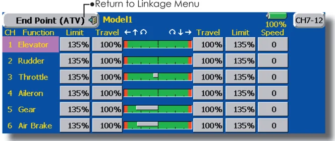
(The display screen is an example. The screen depends on the model type.)
Servo travel adjustment
- Touch the Travel button of the channel you want to set. Adjustment buttons appear on the screen.
- Use these buttons to adjust the rate.
- Initial value: 100%
- Adjustment range: 30%~140%
- Repeat the procedure above for each rate.
Limit point adjustment
- Touch the Limit button of the channel you want to set.
- Use the adjustment buttons to adjust the limit point.
- Initial value: 135%
- Adjustment range: 0%~155%
- Repeat this procedure for each limit point.
Servo speed setting
- Touch the Speed button of the channel you want to set.
- Use the adjustment buttons to adjust the servo speed.
- Initial value: 0
- Adjustment range: 0~25 (steps)
- Repeat this procedure for each channel.
To close this screen, touch the [End Point (ATV)] button.
64 <Linkage Menu>
Throttle Cut
Stops the engine safely and easily.(airplane and helicopter only)
Throttle cut provides an easy way to stop the engine, by flipping a switch with the throttle stick at idle. The action is not functional at high throttle to avoid accidental dead sticks. The switch’s location and direction must be chosen, as it defaults to NULL.
• Touch the [Throttle Cut] button in the Linkage Menu to call the setup screen shown below.
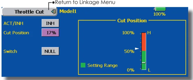
(The display screen is an example. The screen depends on the model type.)
Throttle cut setting procedure
- Touch the "INH" button to activate the Throttle Cut function.
- Throttle cut function switch setting: Touch the "NULL" button to call the <Switch> screen, and then select the switch and its ON direction. (For a detailed description of the selection method, see [Switch Setting Method] at the back of this manual.)
- Throttle cut position setting: Set the throttle stick to maximum slow, and touch the Cut Position button. Adjustment buttons appear. At the same time, the numerical value of the current maximum slow side is displayed at "Cut Position".
Use the adjustment buttons to adjust the servo travel when the throttle cut function is activated.
• Initial value: 17%
• Adjustment range: 0%~50%
*With throttle stick at idle, adjust the rate until the engine consistently shuts off, but throttle linkage is not binding. When finished, touch the “Throttle Cut” button to exit.
To exit the setting, touch the [Throttle Cut] button.
<Linkage Menu> 65
Idle Down
Lowers the engine idling speed.(airplane and helicopter only)
The Idle Down function lowers the engines idle by flipping a switch with the throttle stick at idle. The action is not functional at high throttle to avoid accidental dead sticks. The switch’s location and direction must be chosen, as it defaults to NULL.
- Touch the [Idle Down] button in the Linkage Menu to call the setup screen shown below.
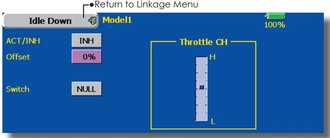
(The display screen is an example. The screen depends on the model type.)
Idle down setting procedure
- Touch the "INH" button to activate the Idle Down function.
- Idle Down function switch setting: Touch the "NULL" button to call the <Switch> screen, and then select the switch and its ON direction. (For a detailed description of the selection method, see [Switch Setting Method] at the back of this manual.)
- Offset rate setting:
Touch the Offset Rate button. Adjustment buttons appear on the screen.
Use these buttons to adjust the offset rate.
- Initial value: 0%
- Adjustment range: 0%~100%
To exit the setting, touch the [Idle Down] button.
66 <Linkage Menu>
Swash
Swash operation linkage correction function.(helicopter only)
Neutral Point
At your linkages, if the servo horn deviates from a perpendicular position at neutral, the linkage compensation functions in this menu may not compensate effectively. To correct this use the Hovering Point function. This will, move the neutral point of the servos to the actual perpendicular position. However, this adjustment changes only the datum point of the compensation functions in this menu, and does not affect the neutral position of other functions.
Swash AFR
Swash AFR function reduces/increases/reverses the rate (travel) of the aileron, elevator and collective pitch functions, by adjusting or reversing the motion of all servos involved in that function, only when using that function. Since H-1 uses one servo for each function, there is no need for Swash AFR in H-1.
•Touch the [Swash] button in the Linkage Menu to call the setup screen shown below.
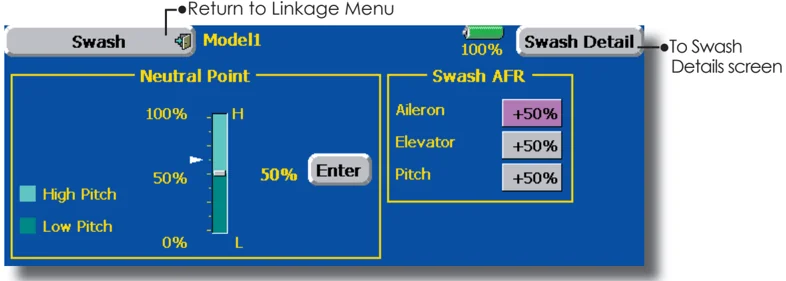
Neutral point setting procedure
*Before using the correction function, set the neutral point. *Adjusting the servo horn so that the neutral point is near the 50% position makes the mixing amount small.
- Hold the servo horn at a right angle to the linkage rod, and then touch the [Enter] button and read the actual neutral position. *The neutral position is displayed on the screen. After reading the neutral point, use the other correction functions to make further adjustments.
To exit the setting, touch the [Swash] button.
Swash AFR setting procedure
- Touch the button of the AFR rate to be adjusted. Adjustment buttons appear on the screen.
- Use these buttons to adjust the AFR rate. •Initial value: +50% •Adjustment range: -100%~+100%
To exit the setting, touch the [Swash] button.
<Linkage Menu> 67
Mixing Rate
This compensation mixing is used to correct the tendency of the swash-plate for each control near the hovering point. The following compensation mixings is possible; PIT to AIL, PIT to ELE, AIL to PIT, ELE to AIL, and ELE to PIT. It adjusts the swash-plate to operate correctly for each control near the hovering point using the corresponding compensation mixings.
Linkage Compensation
This compensation mixing is used to correct the tendency of the swash-plate for pitch control at low pitch and high pitch. It adjusts the swash-plate to move horizontally for collective pitch control using the corresponding compensations.
Elevator Delay/Speed Compensation
This function is used to cancel the reaction when the swash-plate moves in the vertical direction by sudden elevator changes. The delay amount of elevator can be programmed.
 Return to Linkage Menu
To Swash AFR screen
Model1
Swash Detail
Swash AFR
100%
Mixing Rate Mixing \leftarrow \uparrow \leftrightarrow \uparrow \downarrow \rightarrow PIT to AIL 100% 100% PIT to ELE 100% 100% AIL to PIT 100% 100% ELE to AIL 50% 50% ELE to PIT 50% 50%
Linkage Compensation Function Dir. High Pitch \leftarrow \uparrow \leftrightarrow \uparrow \downarrow \rightarrow Aileron + 0% 0% Elevator + 0% 0%
Speed Compensation 0
Mixing rate setting procedure
- Touch the Mixing Rate button you want to set. Adjustment buttons appear on the screen.
- Use these buttons to adjust the mixing rate.
- Initial values: PIT to AIL, PIT to ELE, AIL to PIT: 100%/100% ELE to AIL, ELE to PIT: 50%/50% To end setting, touch the [Swash Details] button.
Linkage correction setting procedure
- Adjust the rate with the adjustment buttons.
- Adjustment range: 0%~100% Note: When using the linkage correction function, readjust swash AFR for maximum blade angles because the maximum rudder angle changes. To end setting, touch the [Swash Details] button.
Speed correction setting procedure
- Use the adjustment buttons to adjust the delay.
- Initial value: 0
- Adjustment range: 0~100 To end setting, touch the [Swash Details] button.
68 <Linkage Menu>
Timer
Timer setting and lap time display.
The Timer function may be set for any desired time, i.e. engine run time, specified times for competitions, etc. Two independent timers are provided for your use. The timers are stored independently with each model, meaning that when you switch between model setups, the timer associated with the new model is brought up automatically.
The timers may be set to start and stop from the motion of any switch or stick. You may set the ON and OFF directions freely. Each timer has a capacity of up to 59 minutes 59 seconds.
Each timer may be set for count-down or count up operation with a target time. Also Split Time may be counted.
If a target time is set and the timer reaches the set time, a buzzer sound for each count is generated.
Countdown timers sound one short beep during the last twenty seconds and two short beeps during the last ten seconds before reaching the target, then a long tone at the target time, and continue counting with displaying a minus (-) sign. Count-up timers also beep the last twenty and ten seconds, beep the target time, and keep counting upwards until shut down.
- Touch the [Timer] button in the Linkage Menu to call the setup screen shown below.
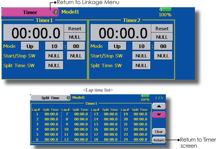
Up timer/down timer selection
- Touch the mode button and select the type of timer. Each time this button is touched, it toggles between UP and DOWN.
- Timer time setting Touch the Mode minutes or seconds button. Adjustment buttons appear on the screen. Use these buttons to set the timer time.
Start/stop switch setting
- Touch the Start/Stop SW "NULL" button to call the <Switch> screen, and then select the switch and its ON direction. (For a detailed description of the selection method, see [Switch Setting Method] at the back of this manual.)
Lap time switch selection
- Touch the Lap SW "NULL" button to call the Prog. Mix screen, and then select the switch and its ON direction. (For a detailed description of the switch setting method, see [Switch Setting Method] at the back of this manual.)
Timer operation
- Timer 1 and Timer 2 are started and stopped by start/stop switch set beforehand.
- To count the lap time, operate the lap time switch selected beforehand. Each time this switch is operated, the lap time is stored. To display the lap time, touch the respective [List] button.
- To reset a timer, touch the respective [Reset] button. To exit the setting, touch the [Timer] button.
<Linkage Menu> 69
Dial Monitor
Displays the position of the dials, slider levers, and digital trim.
Digital Trim Position display (T1-T6, CD)
The Dial Monitor displays the current position and the operation step amount of each Digital Trim.
VR and slide lever position display (LST, LS, LD, RD, RS, RST)
Displays the current position (black▼) and last operating position (green△) of the VRs and slider levers.
- Touch the [Dial Monitor] button in the Linkage Menu to call the setup screen shown below.
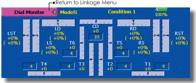
Knob and Lever Position display (LD, RD, LS, LST, RS, RST)
The Dial Monitor displays the current position and last operation position of each knob and lever. Although neither knob nor lever can hold the last operation position because of they are “analog” type, the position data during the last operation is memorized in the model memory. By moving the knob and lever to the position displayed on this monitor, the last operation position is recalled.
Recalling Dial Position (LST, LS, LD, RD, RS, RST)
The dial position data at the last operation is displayed for each knob and lever in this monitor. (Green arrow)
- Move the black arrow (current position) to the green arrow position by operating the desired knob or lever to recall the last operating position.
70 <Linkage Menu>
Data Reset Model memory setting data reset. (by item)
This function is designed to allow you to reset selected portions or all of the settings saved in the active model memory. You may individually choose to reset the following sets of data;
T1~T6, CD: Reset the digital trim setting. *All the conditions, or the condition currently being displayed (the entire group for group setting), can be selected.
Direct key: Resets direct key assignment.
Model menu setting: Resets all the functions in the Model Menu except Condition Select.
All model setting: Resets all Linkage and Model Menu functions except for Frequency, Model Select, and Model Type.
• Touch the [Data Reset] button in the Linkage Menu to call the setup screen shown below.
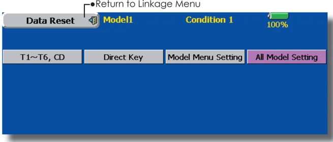
Data Resetting
- Touch the desired button to reset the set of data.
- Perform the data resetting according to the instructions displayed on a screen. When complete, touch the Data Reset button to exit.
<Linkage Menu> 71
MODEL MENU (COMMON FUNCTIONS)
This section describes the AFR, program mixing, and other functions common to all model types.
Before setting the model data, use the Model Type function of the Linkage Menu to select the model type matched to the fuselage. When another model type is selected thereafter, the AFR, program mixing, and other setting data are reset.
The functions in the Model Menu can be set for each flight condition. When you want to use the system by switching the settings for each condition by switch, stick position, etc., use the Condition Select function to add flight conditions. (Up to 8 conditions can be used)
Note: The T14MZ is designed so that the airplane and glider (including EP glider) model types are compatible with fuselages of similar type wings. This section outlines the relationship between the functions common to airplanes and gliders, except some dedicated functions, and model type. The setting items depend on the number of servos and other differences according to the wing type used, but reread them. The setup screens in the instruction manual are typical examples.
- Touch the Model Menu button of the Home screen to call the Model Menu.
- When the button of the function you want to set is touched, a setup screen appears.
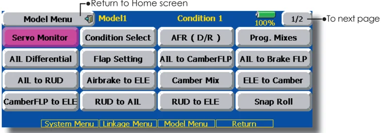
(Model Menu screen example)
The Model Menu screen depends on the model type. This screen is for model type 4AIL+4FLP.
Model Menu functions (Common) list
●Servo Monitor Servo test and servo position display (For a description of its functions, see the Linkage Menu section.)
●Condition Select Flight conditions addition, deletion, copy, condition renaming, and condition delay can be set.
●AFR (D/R) Sets the rudder angle and curve of all the operation functions. A D/R curve which can be switched with a switch, etc. can also be added.
●Prog. Mixes Program mixing which can be freely customized. Up to 10 mixes can be used for each condition.
●Fuel Mixture Mixing used in needle adjustment of engines which use a fuel mixture control carburetor. [Airplane, helicopter]
72 <Model Menu (Common Functions)>
Condition Select
Flight conditions addition, deletion, copy, condition renaming, and condition delay can be set. [All model types]
The functions in the Model Menu can be used by switching the settings of up to 8 flight conditions by using the Condition Select function to add flight conditions. Add conditions, as required.
When you do not want to use the Condition Select function, this setting is unnecessary. In this case, use the flight conditions (Condition 1) assigned at initial setting.
- Since switching by stick and lever position, in addition to ordinary toggle switch, is possible as the flight condition selector switch, this function can be linked with other operations.
- A Condition Delay function can be set. Unnecessary fuselage motion generated when there are sudden changes in the servo positions and when there are variations in the operating time between channels during condition switching can be suppressed. The delay can be set for each channel.
When setting the delay function at the switching destination condition, the related function changes after a delay corresponding to the set amount.
-
When multiple conditions were set, their operation priority can be freely changed.
-
The condition name can be changed. The selected condition name is displayed on the screen. When a condition has been added, give it a name which can be easily confirmed.
-
Touch the [Condition Select] button in the Model Menu to call the setup screen shown below.
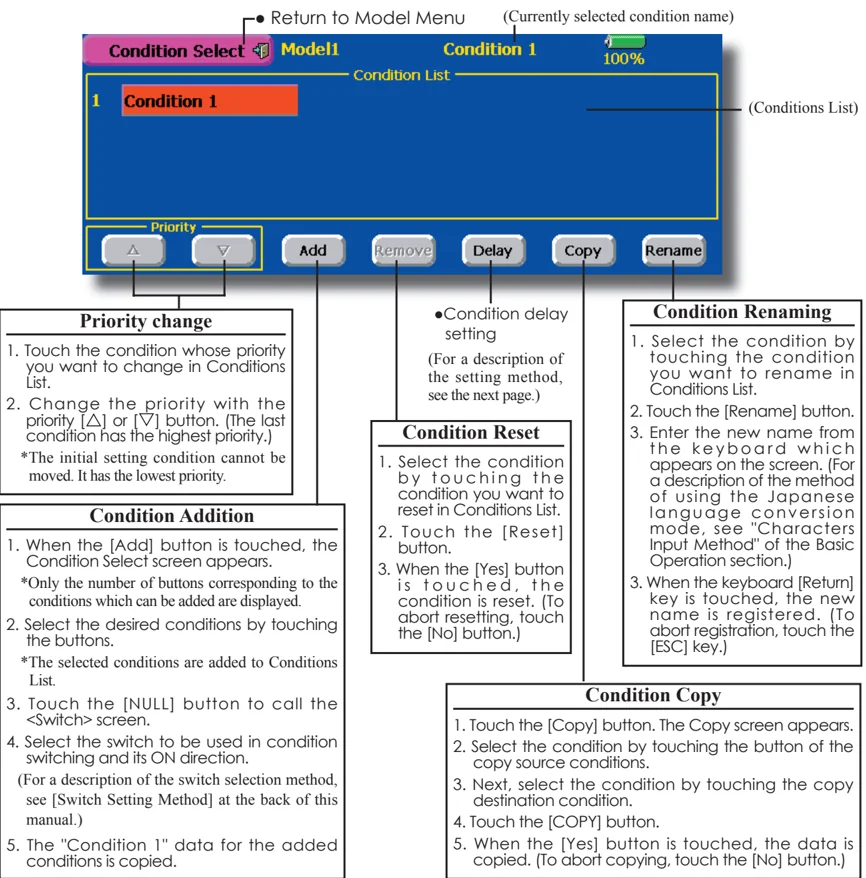
Priority change
- Touch the condition whose priority you want to change in Conditions List.
- Change the priority with the priority [\triangle] or [\nabla] button. (The last condition which can be added has the highest priority.) The initial setting condition cannot be moved. It has the lowest priority.
Condition Addition
- When the [Add] button is touched, the Condition Select screen appears. Only the number of buttons corresponding to the conditions which can be added are displayed.
- Select the desired conditions by touching the buttons. The selected conditions are added to Conditions List.
- Touch the [NULL] button to call the <Switch> screen.
- Select the switch to be used in condition switching and its ON direction. (For a description of the switch selection method, see [Switch Setting Method] at the back of this manual.)
- The "Condition 1" data for the added conditions is copied.
Condition Reset
- Select the condition by touching the condition you want to reset in Conditions List.
- Touch the [Reset] button.
- When the [Yes] button is touched, the condition is reset. (To abort resetting, touch the [No] button.)
Condition Renaming
- Select the condition by touching the condition you want to rename in Conditions List.
- Touch the [Rename] button.
- Enter the new name from the keyboard which appears on the screen. (For a description of the method of using the Japanese language conversion mode, see "Characters Input Method" of the Basic Operation section.)
- When the keyboard [Return] key is touched, the new name is registered. (To abort registration, touch the [ESC] key.)
Condition Copy
- Touch the [Copy] button. The Copy screen appears.
- Select the condition by touching the button of the copy source conditions.
- Next, select the condition by touching the copy destination condition.
- Touch the [COPY] button.
- When the [Yes] button is touched, the data is copied. (To abort copying, touch the [No] button.)
<Model Menu (Common Functions)> 73
- Touch the [Delay] button on the Condition Select screen to call the Condition Delay screen shown below.
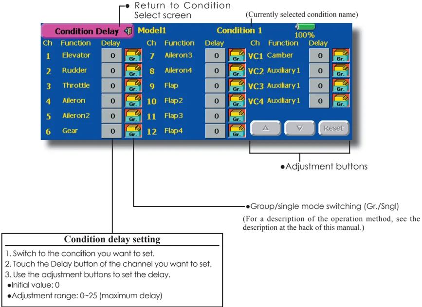
- Adjustment buttons
- Group/single mode switching (Gr./Sngl) (For a description of the operation method, see the description at the back of this manual.)
Condition delay setting
- Switch to the condition you want to set.
- Touch the Delay button of the channel you want to set.
- Use the adjustment buttons to set the delay.
- Initial value: 0
- Adjustment range: 0~25 (maximum delay)
Condition Hold (Helicopter Only)
This function may be used to limit the maximum speed of the engine so that you may adjust flight conditions when the engine is running. The maximum throttle position is settable, and an alarm indicates that the function is operating. The function is especially useful for helicopters, because it will prevent the engine from racing dangerously when adjusting the Idle-Up settings.
While this function is active, the throttle operates on the default condition throttle curve, and mixing is applied as normal, except the throttle is not allowed to move past the set point.
You must deactivate this function when you are through making adjustments. The system will not allow you to deactivate this function in either of the following states:
- When any of the flight condition switches are on.
- When the throttle stick is higher than the set point.
To activate Condition hold:
- Set the throttle stick at a position 3/4 below full throttle.
- Press the Condition Hold box in the lower left hand corner of the Model Menu or Linkage Menu screens.
74 <Model Menu (Common Functions)>
AFR (D/R)
The rudder angle and curve of each operation function can be set. A D/R curve which can be switched by switch, etc. can also be added. [All model types]
AFR function is used to adjust the throw and operation curve of the stick, lever, and switch functions (CH1 to CH12, and V1 to V4) for each flight condition. This is normally used after End Point (ATV) has defined the maximum throw directions (End Point acts on ALL flight condition settings). When mixing is applied from one channel to another channel, both channels can be adjusted at the same time by adjusting the operation rate through the AFR function.
Setting method
-
Operation curve adjustment: Six types of curves (linear, EXP1, EXP2, VTR, line and spline) can be selected. A maximum 17 points curve can be used for the line and spline curve types. (Initial setting: 9 points) The number of points can also be increased and decreased and curves from complex curves to simple curves can be used.
-
Operation speed adjustment: The operation speed of each function when the function is operated (including at flight condition switching) can be adjusted. The function operates smoothly at a constant speed corresponding to the set speed.
-
Touch the [AFR (D/R)] button in the Model Menu to call the setup screen shown below.
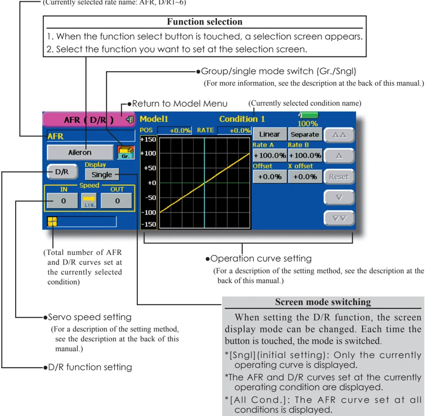
(Currently selected rate name: AFR, D/R1~6)
Function selection
- When the function select button is touched, a selection screen appears.
- Select the function you want to set at the selection screen.
-
Group/single mode switch (Gr./Sngl) (For more information, see the description at the back of this manual.)
-
Return to Model Menu (Currently selected condition name)
(Total number of AFR and D/R curves set at the currently selected condition)
-
Operation curve setting (For a description of the setting method, see the description at the back of this manual.)
-
Servo speed setting (For a description of the setting method, see the description at the back of this manual.)
-
D/R function setting
Screen mode switching
When setting the D/R function, the screen display mode can be changed. Each time the button is touched, the mode is switched.
[Sngl] (initial setting): Only the currently operating curve is displayed.
*The AFR and D/R curves set at the currently operating condition are displayed.
[All Cond.]: The AFR curve set at all conditions is displayed.
<Model Menu (Common Functions)> 75