SECTION 4 – INSTALLATION
4-1. Specifications
A. For Multivoltage Units
| Input Power | Rated Welding Output | Amperage Range | Maximum Open-Circuit Voltage DC | Amperes Input at Rated Load Output 60 Hz | |||
|---|---|---|---|---|---|---|---|
| 230 V | 460 V | KVA | KW | ||||
| Three Phase | 250 A @ 30 Volts AC, 40% Duty Cycle | 5–300 | 95∇6–10♦ | 32*.27 | 16*.15 | 12.8*.09 | 10.0*.04 |
| 200 A @ 28 Volts DC, 40% Duty Cycle | 21.0*.27 | 11.0*.15 | 8.4*.09 | 7.6*.04 | |||
| Single Phase | 250 A @ 30 Volts AC, 40% Duty Cycle | 5–300 | 95∇6–10♦ | 61.0*.33 | 30.0*.18 | 14.0*.10 | 10.0*.07 |
| 200 A @ 28 Volts DC, 40% Duty Cycle | 46.0*.33 | 23.0*.18 | 10.5*.1 | 7.5*.07 |
*While idling
♦ Low open-circuit voltage while in TIG Lift Arc™, or while in Stick with low open-circuit voltage selected (see Section 6-6).
∇Normal open-circuit voltage (95 volts) is present while in Stick with normal open-circuit voltage selected (see Section 6-6).
Note: This unit is equipped with Auto-Link®. Auto-Link is an internal inverter power source circuit that automatically links the power source to the primary voltage being applied (230 to 460 V), without the need for manually linking primary voltage terminals.
B. For Single Voltage Units
| Rated Welding Output | Amperage Range | Maximum Open-Circuit Voltage DC | Amperes Input At Rated Output, 50Hz - Three-Phase 400 V | KVA | KW |
|---|---|---|---|---|---|
| 250 A @ 30 Volts AC, 40% Duty Cycle | 5 – 300 | 95∇6–10♦ | 20.0 (0.13*) | 14.0 (0.09*) | 10.5 (0.04*) |
| 200 A @ 28 Volts DC, 40% Duty Cycle | 5 – 300 | 95∇6–10♦ | 15.0 (0.13*) | 10.5 (0.09*) | 7.5 (0.04*) |
*While idling
♦ Low open-circuit voltage while in TIG Lift Arc™, or while in Stick with low open-circuit voltage selected (see Section 6-6).
∇Normal open-circuit voltage (95 volts) is present while in Stick with normal open-circuit voltage selected (see Section 6-6).
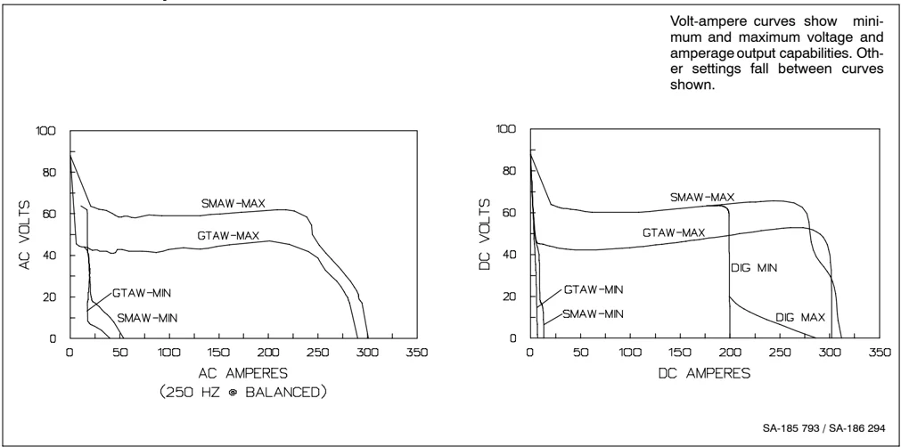
4-2. Volt-Ampere Curves
Volt-ampere curves show minimum and maximum voltage and amperage output capabilities. Other settings fall between curves shown.
SA-185 793 / SA-186 294
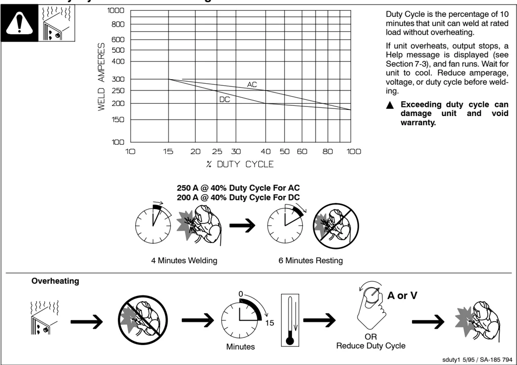
4-3. Duty Cycle and Overheating
Duty Cycle is the percentage of 10 minutes that unit can weld at rated load without overheating.
If unit overheats, output stops, a Help message is displayed (see Section 7-3), and fan runs. Wait for unit to cool. Reduce amperage, voltage, or duty cycle before welding.
▲ Exceeding duty cycle can damage unit and void warranty.
250 A @ 40% Duty Cycle For AC 200 A @ 40% Duty Cycle For DC
4 Minutes Welding 6 Minutes Resting
Overheating
A or V OR Reduce Duty Cycle
sduty1 5/95 / SA-185 794
4-4. Selecting a Location
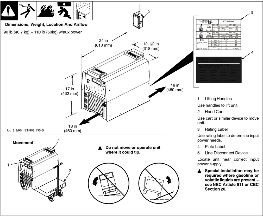
Dimensions, Weight, Location And Airflow 90 lb (40.7 kg) – 110 lb (50kg) w/aux power
loc_2 3/96 - ST-802 135-B
- Lifting Handles Use handles to lift unit.
- Hand Cart Use cart or similar device to move unit.
- Rating Label Use rating label to determine input power needs.
- Plate Label
- Line Disconnect Device Locate unit near correct input power supply.
▲ Do not move or operate unit where it could tip.
▲ Special installation may be required where gasoline or volatile liquids are present – see NEC Article 511 or CEC Section 20.
4-5. 115 Volts AC Duplex Receptacle, Supplementary Protector CB1 (Optional), And Power Switch
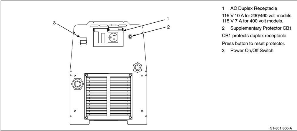
- AC Duplex Receptacle 115 V 10 A for 230/460 volt models. 115 V 7 A for 400 volt models.
- Supplementary Protector CB1 CB1 protects duplex receptacle. Press button to reset protector.
- Power On/Off Switch
ST-801 866-A
4-6. Weld Output Terminals And Selecting Cable Sizes*
▲ ARC WELDING can cause Electromagnetic Interference. To reduce possible interference, keep weld cables as short as possible, close together, and down low, such as on the floor. Locate welding operation 100 meters from any sensitive electronic equipment. Be sure this welding machine is installed and grounded according to this manual. If interference still occurs, the user must take extra measures such as moving the welding machine, using shielded cables, using line filters, or shielding the work area.
\begin{tabular}{|p{0.18\textwidth}|c|c|c|c|c|c|c|c|} \hline \multicolumn{1}{|c|}{\textbf{Weld Output}} & \multicolumn{8}{c|}{\textbf{Weld Cable Size** and Total Cable (Copper) Length in Weld Circuit Not Exceeding}} \ \cline{2-9} \multicolumn{1}{|c|}{\textbf{Terminals}} & \multirow{2}{}{\textbf{Welding Amps**}} & \textbf{100 ft (30 m) or Less} & \textbf{150 ft (45 m)} & \textbf{200 ft (60 m)} & \textbf{250 ft (70 m)} & \textbf{300 ft (90 m)} & \textbf{350 ft (105 m)} & \textbf{400 ft (120 m)} \ \cline{3-9} \multicolumn{1}{|c|}{\textbf{Turn off power before connecting to weld output terminals.}} & & \textbf{10 – 60% Duty Cycle} & \textbf{60 – 100% Duty Cycle} & \multicolumn{5}{c|}{\textbf{10 – 100% Duty Cycle}} \ \multicolumn{1}{|c|}{\textbf{Do not use worn, damaged, undersized, or poorly spliced cables.}} & & & & & & & & \ \hline & 100 & 4 (20) & 4 (20) & 4 (20) & 3 (30) & 2 (35) & 1 (50) & 1/0 (60) & 1/0 (60) \ \hline & 150 & 3 (30) & 3 (30) & 2 (35) & 1 (50) & 1/0 (60) & 2/0 (70) & 3/0 (95) & 3/0 (95) \ \hline & 200 & 3 (30) & 2 (35) & 1 (50) & 1/0 (60) & 2/0 (70) & 3/0 (95) & 4/0 (120) & 4/0 (120) \ \hline & 250 & 2 (35) & 1 (50) & 1/0 (60) & 2/0 (70) & 3/0 (95) & 4/0 (120) & 2 ea. 2/0 (2x70) & 2 ea. 2/0 (2x70) \ \hline & 300 & 1 (50) & 1/0 (60) & 2/0 (70) & 3/0 (95) & 4/0 (120) & 2 ea. 2/0 (2x70) & 2 ea. 3/0 (2x95) & 2 ea. 3/0 (2x95) \ \hline & 350 & 1/0 (60) & 2/0 (70) & 3/0 (95) & 4/0 (120) & 2 ea. 2/0 (2x70) & 2 ea. 3/0 (2x95) & 2 ea. 3/0 (2x95) & 2 ea. 4/0 (2x120) \ \hline \end{tabular}
- This chart is a general guideline and may not suit all applications. If cable overheats, use next size larger cable. **Weld cable size (AWG) is based on either a 4 volts or less drop or a current density of at least 300 circular mils per ampere. ( ) = mm² for metric use ***Select weld cable size for pulsing application at peak amperage value.
S-0007-E-
4-7. Remote 14 Receptacle Information
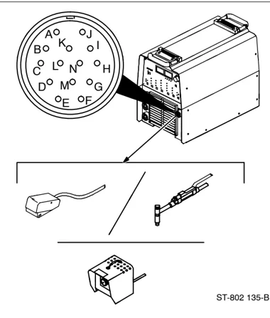
ST-802 135-B
\begin{tabular}{|l|c|p{0.5\textwidth}|} \hline \textbf{REMOTE 14} & \textbf{Socket*} & \textbf{Socket Information} \ \hline \textbf{24 VOLTS DC OUTPUT (CONTACTOR)} & A & Contactor control, 24 volts dc. \ \cline{2-3} & B & Contact closure to A completes 24 volts dc contactor control circuit, and enables output. \ \hline \textbf{REMOTE OUTPUT CONTROL} & C & Output to remote control; 0 to +10 volts dc output to remote control. \ \cline{2-3} & D & Remote control circuit common. \ \cline{2-3} & E & 0 to +10 volts dc input command signal from remote control. \ \hline \textbf{A/V AMPERAGE VOLTAGE} & F & Current feedback; +1 volt dc per 100 amperes. \ \cline{2-3} & H & Voltage feedback; +1 volt dc per 10 output receptacle volts. \ \hline \textbf{GND} & G & Reference to pin A \ \hline \textbf{CHASSIS} & K & Chassis common. \ \hline \end{tabular}
*The remaining sockets are not used. If a remote hand control (RHC-14) is connected to this Remote 14 receptacle and the remote control is set at minimum when the welding power source is turned on, the Sequencer function is disabled.

4-8. Gas Connections
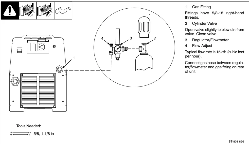
Tools Needed: 5/8, 1-1/8 in
1 Gas Fitting Fittings have 5/8-18 right-hand threads. 2 Cylinder Valve Open valve slightly to blow dirt from valve. Close valve. 3 Regulator/Flowmeter 4 Flow Adjust Typical flow rate is 15 cfh (cubic feet per hour). Connect gas hose between regulator/flowmeter and gas fitting on rear of unit.
ST-801 866
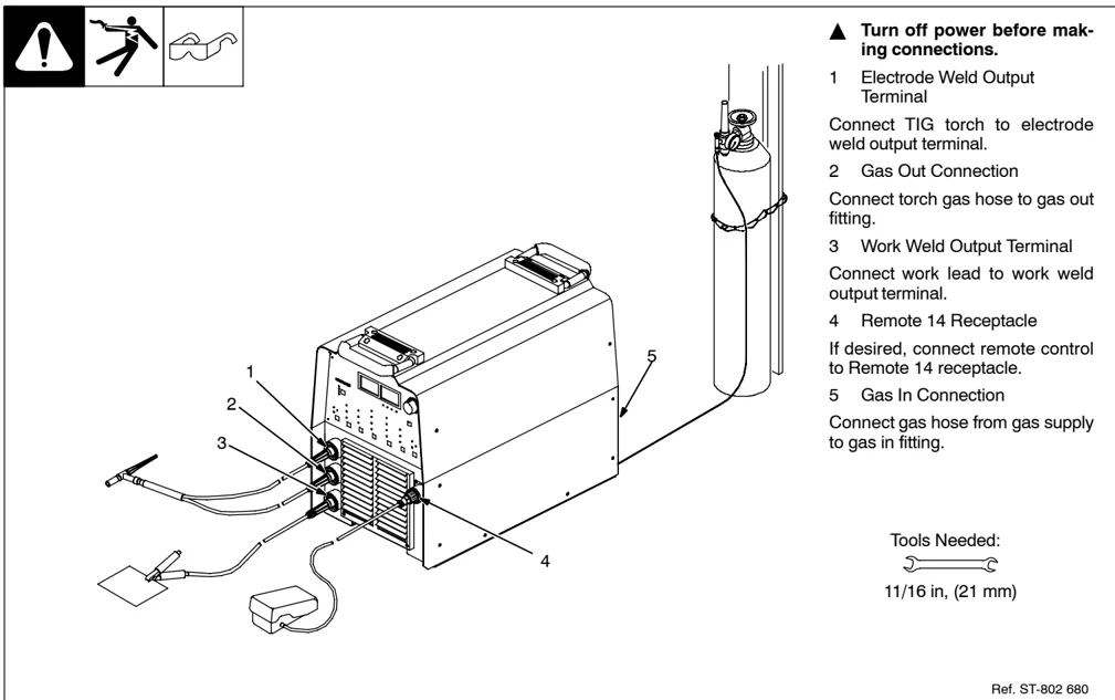
4-9. TIG HF Impulse/ Lift-Arc™ Connections
▲ Turn off power before making connections.
1 Electrode Weld Output Terminal Connect TIG torch to electrode weld output terminal. 2 Gas Out Connection Connect torch gas hose to gas out fitting. 3 Work Weld Output Terminal Connect work lead to work weld output terminal. 4 Remote 14 Receptacle If desired, connect remote control to Remote 14 receptacle. 5 Gas In Connection Connect gas hose from gas supply to gas in fitting.
Tools Needed: 11/16 in, (21 mm)
Ref. ST-802 680
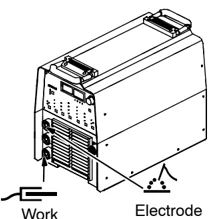
4-10. Stick Connections
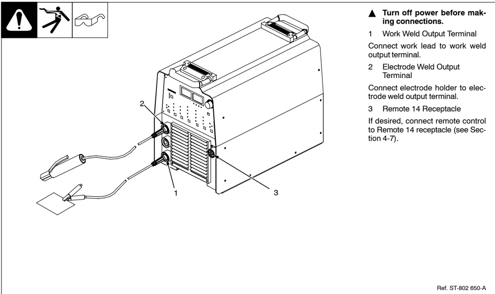
▲ Turn off power before making connections.
1 Work Weld Output Terminal
Connect work lead to work weld output terminal.
2 Electrode Weld Output Terminal
Connect electrode holder to electrode weld output terminal.
3 Remote 14 Receptacle
If desired, connect remote control to Remote 14 receptacle (see Section 4-7).
Ref. ST-802 650-A
4-11. Electrical Service Guide
▲ CAUTION: INCORRECT INPUT POWER can damage this welding power source. This welding power source requires a CONTINUOUS supply of input power at rated frequency (±10%) and voltage (±10%). Phase to ground voltage shall not exceed +10% of rated input voltage. Do not use a generator with automatic idle device (that idles engine when no load is sensed) to supply input power to this welding power source.
| Three Phase | Single Phase | ||||
|---|---|---|---|---|---|
| Input Voltage | 230 | *400 | 460 | 230 | 460 |
| Input Amperes At Rated Output | 32 | 20 | 16 | 61 | 30 |
| Max Recommended Standard Fuse Rating In Amperes¹ | |||||
| Time-Delay ² | 40 | 25 | 20 | 70 | 35 |
| Normal Operating ³ | 50 | 30 | 25 | 90 | 45 |
| Min Input Conductor Size In AWG ⁴ | 10 | 14 | 14 | 8 | 12 |
| Max Recommended Input Conductor Length In Feet (Meters) | 127 (39) | 144 (44) | 201 (61) | 94 (29) | 154 (47) |
| Min Grounding Conductor Size In AWG ⁴ | 10 | 14 | 14 | 8 | 12 |
*For 400 Volt Single Voltage Model
Reference: 2005 National Electrical Code (NEC) (including article 630)
1 Consult factory for circuit breaker applications.
2 “Time-Delay” fuses are UL class “RK5”.
3 “Normal Operating” (general purpose - no intentional delay) fuses are UL class “K5” (up to and including 60 amp), and UL class “H” (65 amp and above).
4 Conductor data in this section specifies conductor size (excluding flexible cord or cable) between the panelboard and the equipment per NEC Table 310.16. If a flexible cord or cable is used, minimum conductor size may increase. See NEC Table 400.5(A) for flexible cord and cable requirements.
4-12. Connecting 3-Phase Input Power
 = GND/PE Earth Ground
Tools Needed:
▲ Installation must meet all National and Local Codes – have only qualified persons make this installation.
▲ Disconnect and lockout/tagout input power before connecting input conductors from unit.
▲ Always connect green or green/yellow conductor to supply grounding terminal first, and never to a line terminal.
This unit is equipped with Auto-Link. Auto-Link is an internal inverter power source circuit that automatically links the power source to the primary voltage being applied (230 to 460 V), without the need for manually linking primary voltage terminals.
For Three-Phase Operation
1 Input Power Cord. 2 Disconnect Device (switch shown in the OFF position) 3 Green Or Green/Yellow Grounding Conductor 4 Disconnect Device Grounding Terminal 5 Input Conductors (L1, L2 And L3) 6 Disconnect Device Line Terminals
Connect green or green/yellow grounding conductor to disconnect device grounding terminal first.
Connect input conductors L1, L2, and L3 to disconnect device line terminals.
7 Overcurrent Protection
Select type and size of overcurrent protection using Section 4-11 (fused disconnect switch shown).
Close and secure door on disconnect device. Remove lockout/tagout device, and place switch in the On position.
2/04 - Ref. 802 136-A
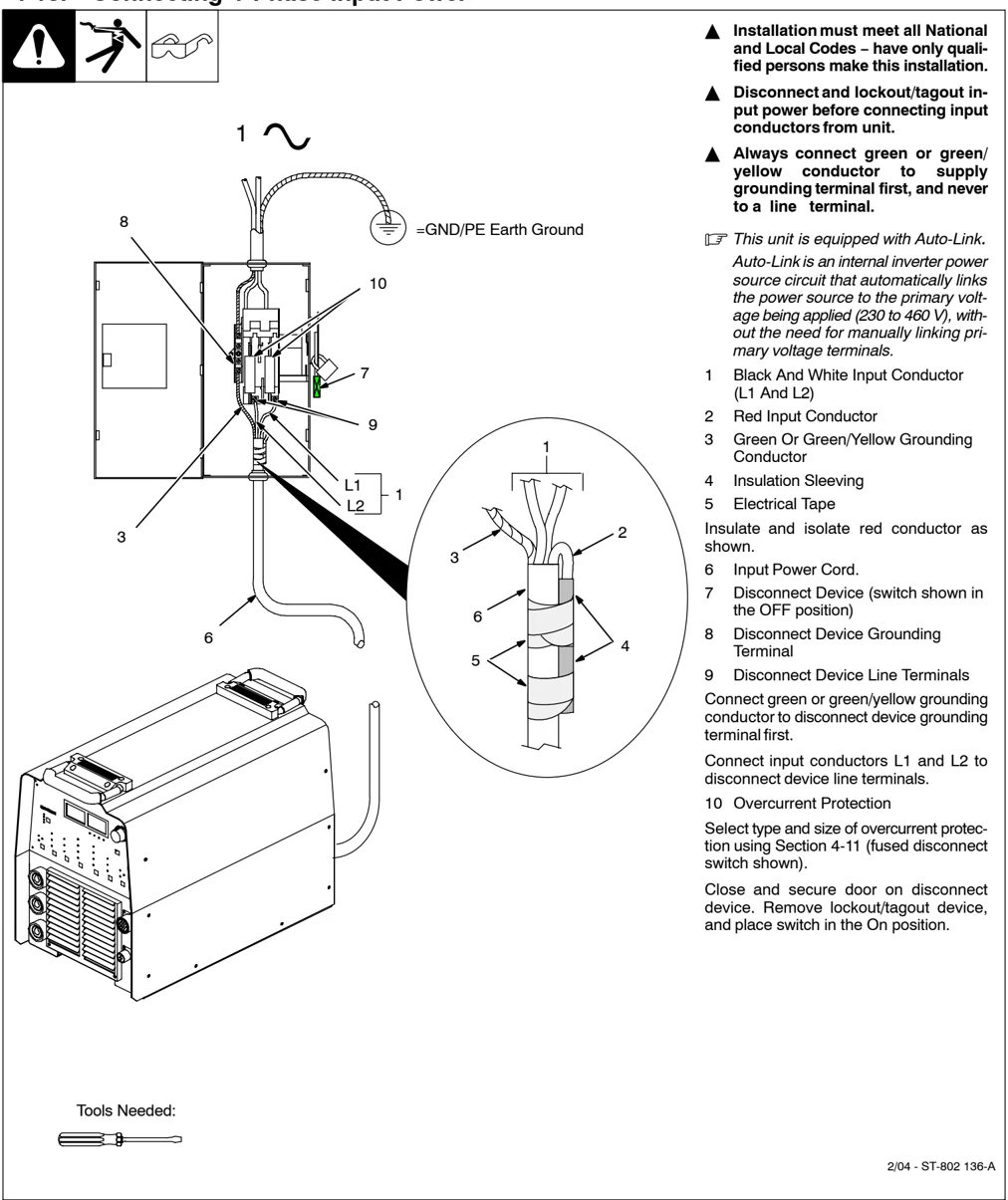
4-13. Connecting 1-Phase Input Power
Tools Needed:
▲ Installation must meet all National and Local Codes – have only qualified persons make this installation.
▲ Disconnect and lockout/tagout input power before connecting input conductors from unit.
▲ Always connect green or green/yellow conductor to supply grounding terminal first, and never to a line terminal.
This unit is equipped with Auto-Link. Auto-Link is an internal inverter power source circuit that automatically links the power source to the primary voltage being applied (230 to 460 V), without the need for manually linking primary voltage terminals.
1 Black And White Input Conductor (L1 And L2) 2 Red Input Conductor 3 Green Or Green/Yellow Grounding Conductor 4 Insulation Sleeving 5 Electrical Tape Insulate and isolate red conductor as shown. 6 Input Power Cord. 7 Disconnect Device (switch shown in the OFF position) 8 Disconnect Device Grounding Terminal 9 Disconnect Device Line Terminals Connect green or green/yellow grounding conductor to disconnect device grounding terminal first. Connect input conductors L1 and L2 to disconnect device line terminals. 10 Overcurrent Protection Select type and size of overcurrent protection using Section 4-11 (fused disconnect switch shown). Close and secure door on disconnect device. Remove lockout/tagout device, and place switch in the On position.
2/04 - ST-802 136-A
SECTION 5 – OPERATION
5-1. Controls
ST-198 708 / ST-802 452
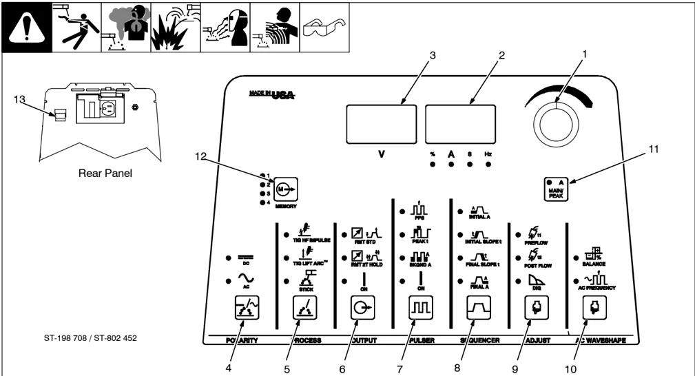
For all front panel switch pad controls: press switch pad to turn on light and enable normal function.
NOTE: Green on nameplate indicates a TIG function, Gray indicates a normal Stick function.
- Encoder Control See Section 5-4.
- Ammeter And Parameter Display See Section 5-5.
- Voltmeter See Section 5-5.
- Polarity Control See Section 5-6.
- Process Controls See Section 5-7.
- Output Controls See Section 5-9.
- Pulser Controls (DX And LX Models) See Section 5-10.
- Sequencer Controls (DX, LX And All CE Models) See Section 5-11.
- Adjust Controls See Section 5-12.
- AC Waveshape See Section 5-13.
- Amperage And Spot Time Control For Amperage Control see Section 5-3. For Spot Time Control see Section 5-14.
- Memory See Section 5-15.
- Power Switch Use switch to turn unit On/Off.
5-2. Encoder Control
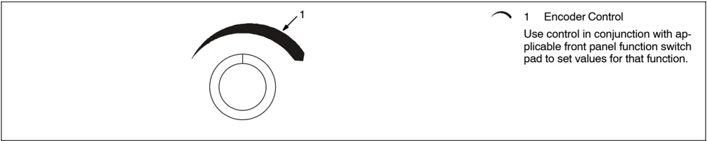
- Encoder Control Use control in conjunction with applicable front panel function switch pad to set values for that function.
5-3. Amperage Control
 1 A (Amperage Control)
2 Encoder Control
3 Ammeter
See Section 5-17 for Amperage control range.
Press Amperage switch pad, and turn Encoder to set weld amperage or peak amperage when Pulser function is active (see Section 5-10).
5-4. Ammeter And Parameter Display
 1 Ammeter
Ammeter displays amperage while welding. It also displays preset parameters for any of the following: amperage, time, percentage or frequency. The LED, located directly below the ammeter, will also illuminate.
5-5. Voltmeter
 1 Volt Meter
Displays output or open circuit voltage. If output is off, the voltmeter will display (---).
5-6. Polarity Control (Dynasty™ Models Only)
 1 Polarity Control
Press switch pad until desired LED is illuminated.
DC - Machine is set to DCEN for TIG welding, and to DCEP for Stick welding.
AC - Use AC for TIG and Stick welding.
5-7. Process Control
 1 Process Control
Press switch pad until desired process LED is illuminated:
TIG HF Impulse - is a pulsed HF (see Section 5-8) arc starting method that can be used with either AC or DC TIG welding. Make connections according to Section 4-9.
TIG Lift-Arc™ - is an arc starting method in which the electrode must come in contact with the workpiece (see Section 5-8). This method can be used with either AC or DC TIG welding. Make connections according to Section 4-9.
Stick (SMAW) - This method can be used with either AC or DC Stick welding. Make connections according to Section 4-10.
5-8. Lift-Arc™ And HF TIG Start Procedures
 Lift-Arc Start Method
1
2
"Touch"
1 – 2 Seconds
Do NOT Strike Like A Match!
Lift-Arc Start
When Lift-Arc™ button light is On, start arc as follows:
1 TIG Electrode 2 Workpiece
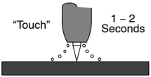
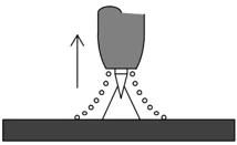
Touch tungsten electrode to workpiece at weld start point, enable output and shielding gas with torch trigger, foot control, or hand control. Hold electrode to workpiece for 1-2 seconds, and slowly lift electrode. Arc is formed when electrode is lifted.
Normal open-circuit voltage is not present before tungsten electrode touches workpiece; only a low sensing voltage is present between electrode and workpiece. The solid-state output contactor does not energize until after electrode is touching workpiece. This allows electrode to touch workpiece without overheating, sticking, or getting contaminated.
Application: Lift-Arc is used for the DCEN or AC GTAW process when HF Start method is not permitted, or to replace the scratch method.
HF Start
When HF Start button light is On, start arc as follows:
High frequency turns on to help start arc when output is enabled. High frequency turns off when arc is started, and turns on whenever arc is broken to help restart arc.
Application: HF start is used for the DCEN GTAW process when a non-contact arc starting method is required.
5-9. Output Control
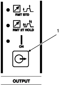
1 Output Control Press switch pad until desired parameter LED is illuminated.
RMT STD (Remote Standard) Application: Use Remote Trigger (Standard) with a foot pedal or finger amperage control (see Section 6-2A). NOTE: When a foot or finger remote current control is connected, initial amps, initial slope, final slope, and final amps are controlled by the remote control. NOTE: If an On/Off type trigger is used, it must be a maintained switch. All Sequencer functions become active, and must be set by the operator.
RMT 2T HOLD Application: Use Remote Trigger Hold (2T) for long extended welds. If a foot or finger current control is connected to the welding power source, only trigger input is functional (see Section 6-2B). NOTE: This switch function can be reconfigured for 4T, 4T Momentary, Mini Logic, or Spot control See Section 6-2C)
ON Output will energize two seconds after being selected. Application: Use Output On for Stick (SMAW) welding, or for Lift-Arc without the use of a remote control (see Section 6-2I).
5-10. Pulser Control (DX And LX Models)
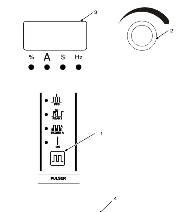
1 Pulser Control Pulsing is available while using the TIG process. Controls can be adjusted while welding.
Press switch pad to enable pulser.
ON - When illuminated, this LED indicates the pulser is on.
Press switch pad until desired parameter LED is illuminated.
To turn Pulser off, press and release switch pad until the On LED turns off.
2 Encoder Control (Set Value)
3 Ammeter (Displays Value)
See Section 5-17 for all Pulser parameter ranges.
PPS (Pulses Per Second or Pulse Frequency) Used to determine appearance of weld bead.
PEAK t - The percentage of each pulse cycle that can be spent at the peak amperage level.
BKGNDA (Background Amps) - Use Background Amps to set the low pulse of the weld amperage, which cools the weld puddle and affects overall heat input. Background Amps is a percentage of peak amperage.
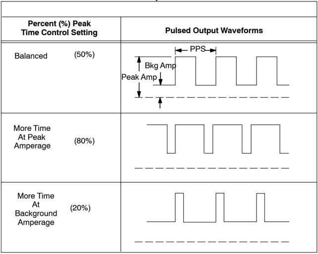
4 Pulsed Output Waveforms
Example shows affect changing the Peak Time control has on the pulsed output waveform.
NOTE: Peak amperage is set using the Amperage control (see Section 5-3). Peak amperage is the highest welding amperage allowed in the pulse cycle. Weld penetration varies directly with peak amperage.
Application:
Pulsing is the alternating raising and lowering of the weld output at a specific rate. The raised portions of the weld output are controlled in width, height, and frequency, forming pulses of weld output. These pulses and the lower amperage level between them (called the background amperage) alternately heat and cool the molten weld puddle. The combined effect gives better control of penetration, bead width, crowning, undercutting, and heat input.
| Percent (%) Peak Time Control Setting | Pulsed Output Waveforms |
|---|---|
| Balanced (50%) | |
| More Time At Peak Amperage (80%) | |
| More Time At Background Amperage (20%) |
5-11. Sequencer Controls (DX, LX And All CE Models)
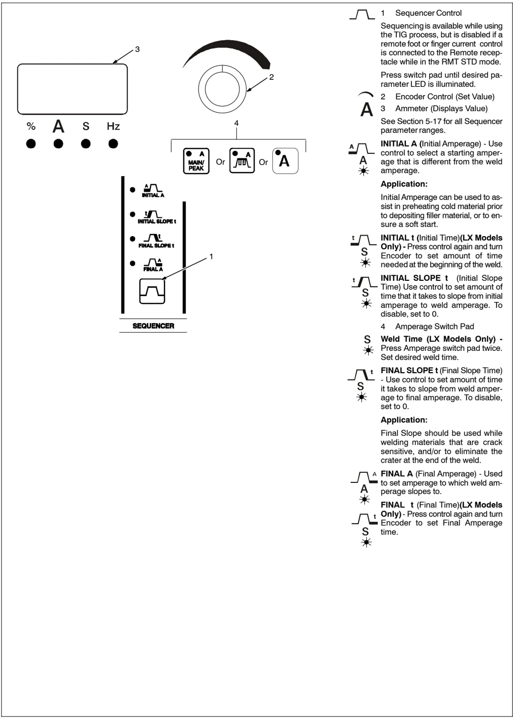
1 Sequencer Control Sequencing is available while using the TIG process, but is disabled if a remote foot or finger current control is connected to the Remote receptacle while in the RMT STD mode. Press switch pad until desired parameter LED is illuminated.
2 Encoder Control (Set Value)
3 Ammeter (Displays Value) See Section 5-17 for all Sequencer parameter ranges.
INITIAL A (Initial Amperage) - Use control to select a starting amperage that is different from the weld amperage.
Application: Initial Amperage can be used to assist in preheating cold material prior to depositing filler material, or to ensure a soft start.
INITIAL t (Initial Time)(LX Models Only) - Press control again and turn Encoder to set amount of time needed at the beginning of the weld.
INITIAL SLOPE t (Initial Slope Time) Use control to set amount of time that it takes to slope from initial amperage to weld amperage. To disable, set to 0.
4 Amperage Switch Pad
Weld Time (LX Models Only) - Press Amperage switch pad twice. Set desired weld time.
FINAL SLOPE t (Final Slope Time) - Use control to set amount of time it takes to slope from weld amperage to final amperage. To disable, set to 0.
Application: Final Slope should be used while welding materials that are crack sensitive, and/or to eliminate the crater at the end of the weld.
FINAL A (Final Amperage) - Used to set amperage to which weld amperage slopes to.
FINAL t (Final Time)(LX Models Only) - Press control again and turn Encoder to set Final Amperage time.
5-12. Adjust Controls (Preflow/Post Flow/DIG/Purge)
 Some features shown are not available on all models.
1 Adjust Press switch pad until desired function LED is illuminated.
2 Encoder Control (Set Value)
3 Ammeter (Displays Value) See Section 5-17 for all Adjust parameter ranges.
PREFLOW - If the TIG HF process is active (see Section 5-7) and Preflow is shown on the control panel, use control to set length of time gas flows before arc initiation. To set Preflow time for models that do not have Preflow Time control on the front panel, see Section 5-16.
Application: Preflow is used to purge the weld area, and aids in arc starts.
POST FLOW - If the TIG process is active (see Section 5-7), use control to set length of time gas flows after welding stops.
Application: Postflow is required to cool tungsten and weld, and to prevent contamination of tungsten and weld. Increase postflow time if tungsten or weld are dark in appearance.
DIG - If the DC Stick process is active (see Section 5-7), use control to set amount of DIG. When set at 0, short-circuit amperage at low arc voltage is the same as normal welding amperage.
When setting is increased, short-circuit amperage at low arc voltage increases.
Application: Control helps arc starting or making vertical or overhead welds by increasing amperage at low arc voltage, and reduces electrode sticking while welding.
PURGE - To activate the gas valve and start the purge function, push and hold the Adjust switch pad for the desired amount of time. To set from 1 to 50 seconds of purge time, hold the Adjust switch pad while turning the encoder control. Default is 0.
While Purge is active, {P-} is shown in the left display, and purge time is shown in the right display.
Pressing any switch pad will end the purge display, but gas will continue to flow until the preset time has timed out.
Application: Purge is used to clear the gas lines.
5-13. AC Waveshape (Dynasty Models Only)
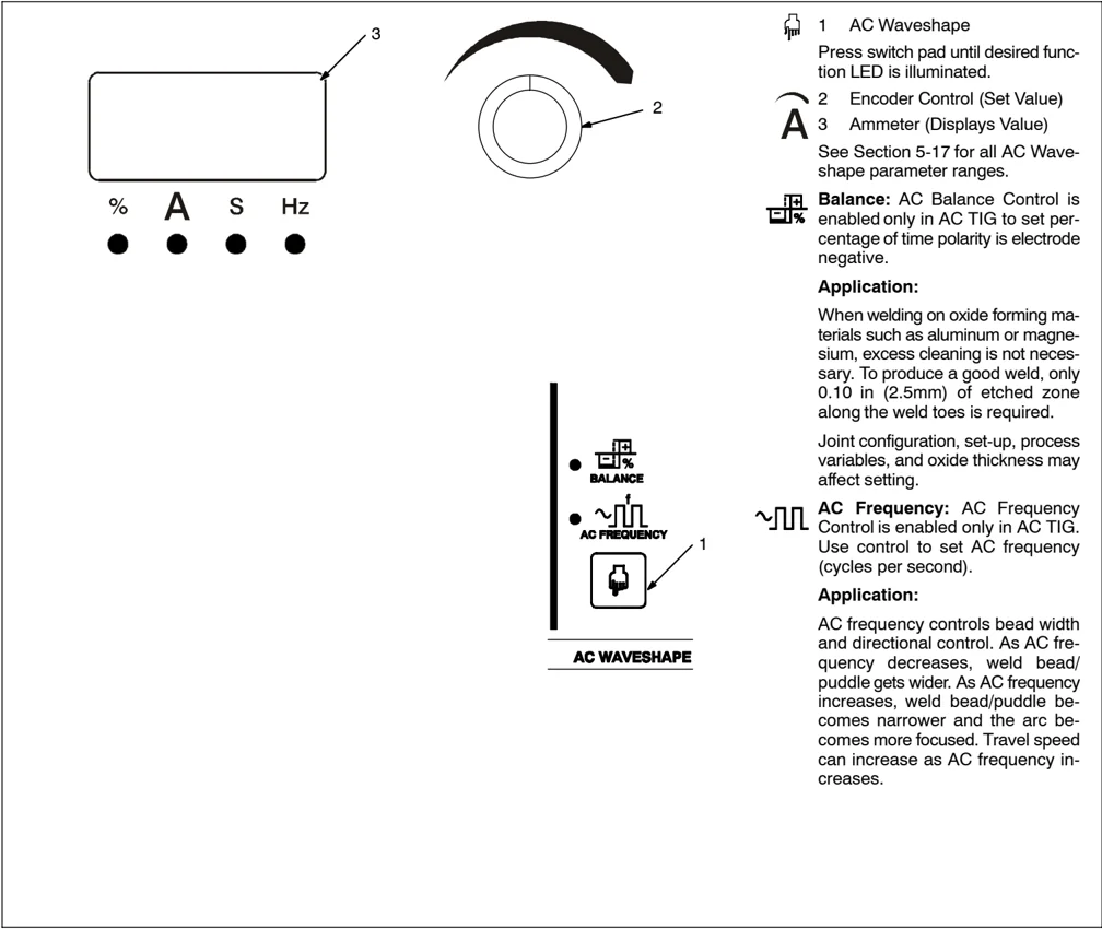
1 AC Waveshape Press switch pad until desired function LED is illuminated. 2 Encoder Control (Set Value) 3 Ammeter (Displays Value) See Section 5-17 for all AC Waveshape parameter ranges.
Balance: AC Balance Control is enabled only in AC TIG to set percentage of time polarity is electrode negative.
Application: When welding on oxide forming materials such as aluminum or magnesium, excess cleaning is not necessary. To produce a good weld, only 0.10 in (2.5mm) of etched zone along the weld toes is required.
Joint configuration, set-up, process variables, and oxide thickness may affect setting.
AC Frequency: AC Frequency Control is enabled only in AC TIG. Use control to set AC frequency (cycles per second).
Application: AC frequency controls bead width and directional control. As AC frequency decreases, weld bead/puddle gets wider. As AC frequency increases, weld bead/puddle becomes narrower and the arc becomes more focused. Travel speed can increase as AC frequency increases.
5-14. Spot Time Control (Reconfigured RMT 2T HOLD Output Selection) (All Models)
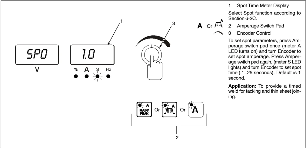
1 Spot Time Meter Display Select Spot function according to Section 6-2C. 2 Amperage Switch Pad 3 Encoder Control
To set spot parameters, press Amperage switch pad once (meter A LED turns on) and turn Encoder to set spot amperage. Press Amperage switch pad again, (meter S LED lights) and turn Encoder to set spot time (.1–25 seconds). Default is 1 second.
Application: To provide a timed weld for tacking and thin sheet joining.
5-15. Memory (Program Storage Locations 1-4) (DX And LX Models If Available)
 Some features shown are not available on all models.
- Memory (Program Storage 1-4) Switch Pad
- Polarity Switch Pad
- Process Switch Pad
To create, change, or recall a welding parameters program, proceed as follows:
First, press Memory switch pad until the desired program storage location (1-4) LED is illuminated
Second, press Polarity switch pad until the desired polarity, AC or DC, LED is illuminated
Third, press Process switch pad until desired process, TIG HF Impulse, TIG Lift Arc, or Stick, LED is illuminated.
The program at the chosen location, for the desired polarity and process, is now the active program.
Fourth, change or set all desired parameters (see Section 5-1 for parameters).
Memory Locations 1–4
AC And TIG (HF or Lift) And Stick
DC And TIG (HF or Lift) And Stick
Each memory location (1 thru 4) can store parameters for both polarities, and each polarity can store parameters for both process (TIG or Stick) for a total of 16 programs.
5-16. Setting Preflow Time For Use With TIG HF Impulse On Models That Do Not Have A Preflow Control On The Front Panel
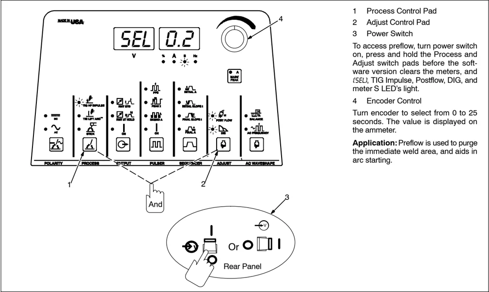
- Process Control Pad
- Adjust Control Pad
- Power Switch
- Encoder Control
To access preflow, turn power switch on, press and hold the Process and Adjust switch pads before the software version clears the meters, and (SEL), TIG Impulse, Postflow, DIG, and meter S LED's light.
Turn encoder to select from 0 to 25 seconds. The value is displayed on the ammeter.
Application: Preflow is used to purge the immediate weld area, and aids in arc starting.
5-17. Factory Parameter Defaults And Range And Resolution
| Parameter | Default | Range And Resolution |
|---|---|---|
| MEMORY | 1 | 1–4 |
| POLARITY | DC | AC / DC |
| PROCESS**Stick OCV | TIG HF ImpulseLow OCV | TIG HF Impulse / TIG Lift / StickLow OCV / Normal OCV |
| OUTPUT**RMT 2T | RMT STD2T | RMT STD / RMT 2T / ONRMT 2T can be reconfigured for: 2T / 4T / Mini Logic / 4T Momentary / Spot (see Section 6-2C) |
| A MAIN / PEAKAC TIGAC STICKDC TIGDC STICK | 150 A110 A150 A110 A | 5 – 300 Amps5 – 300 Amps5 – 300 Amps5 – 300 Amps |
| Spot Time***Weld Time | 1.0 S0 S | 0.1 – 25.0 SecondsDual Range And Resolution0.0 – 99.9 / 100 – 999 Seconds |
| PULSERPPSPEAK tBKGND A**Display PPP While Pulse Welding | Off100 Hz40%25%Off | ON / OFFDual Range And Resolution0.1 – 9.9 / 10 – 500 Hertz5 – 95 Percent5 – 95 PercentOff / On |
| SEQUENCERINITIAL A***Initial TimeINITIAL SLOPE tFINAL SLOPE tFINAL A***Final Time | 20 A0 S0 S0 S5 A0 S | 5 – 300 Amps0.0 – 25.0 Seconds0.0 – 25.0 Seconds0.0 – 25.0 Seconds5 – 300 Amps0.0 – 25.0 Seconds |
| ADJUSTPREFLOWPOST FLOWDIG | 0.2 S10.0 S30% | 0.0 – 25.0 Seconds0.0 – 50.0 Seconds @ 0.2 Second Resolution0 – 100 Percent |
| AC WAVESHAPEBALANCEFREQUENCY | 75%120 Hz | 30 – 99 Percent20 – 250 Hertz |
| **Impulse HF Start parameters for each program (1-4)DC:PolarityAmperageTimeAC:PolarityAmperageTime | EN30 A3 mSEP40 A40 mS | EP / EN5 – 200 Amps1 – 200 MillisecondsEP / EN5 – 200 Amps1 – 200 Milliseconds |
| ** Parameter adjusted using a power up configuration only*** Parameter used with the automation option (LX models only) |
5-18. Resetting Unit To Factory Default Settings (All Models)
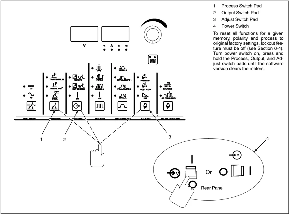
1 Process Switch Pad 2 Output Switch Pad 3 Adjust Switch Pad 4 Power Switch
To reset all functions for a given memory, polarity and process to original factory settings, lockout feature must be off (see Section 6-4). Turn power switch on, press and hold the Process, Output, and Adjust switch pads until the software version clears the meters.