SECTION 8 – ELECTRICAL DIAGRAM
WARNING ELECTRIC SHOCK HAZARD
- Do not touch live electrical parts.
- Disconnect input power or stop engine before servicing.
- Do not operate with covers removed.
- Have only qualified persons install, use, or service this unit.
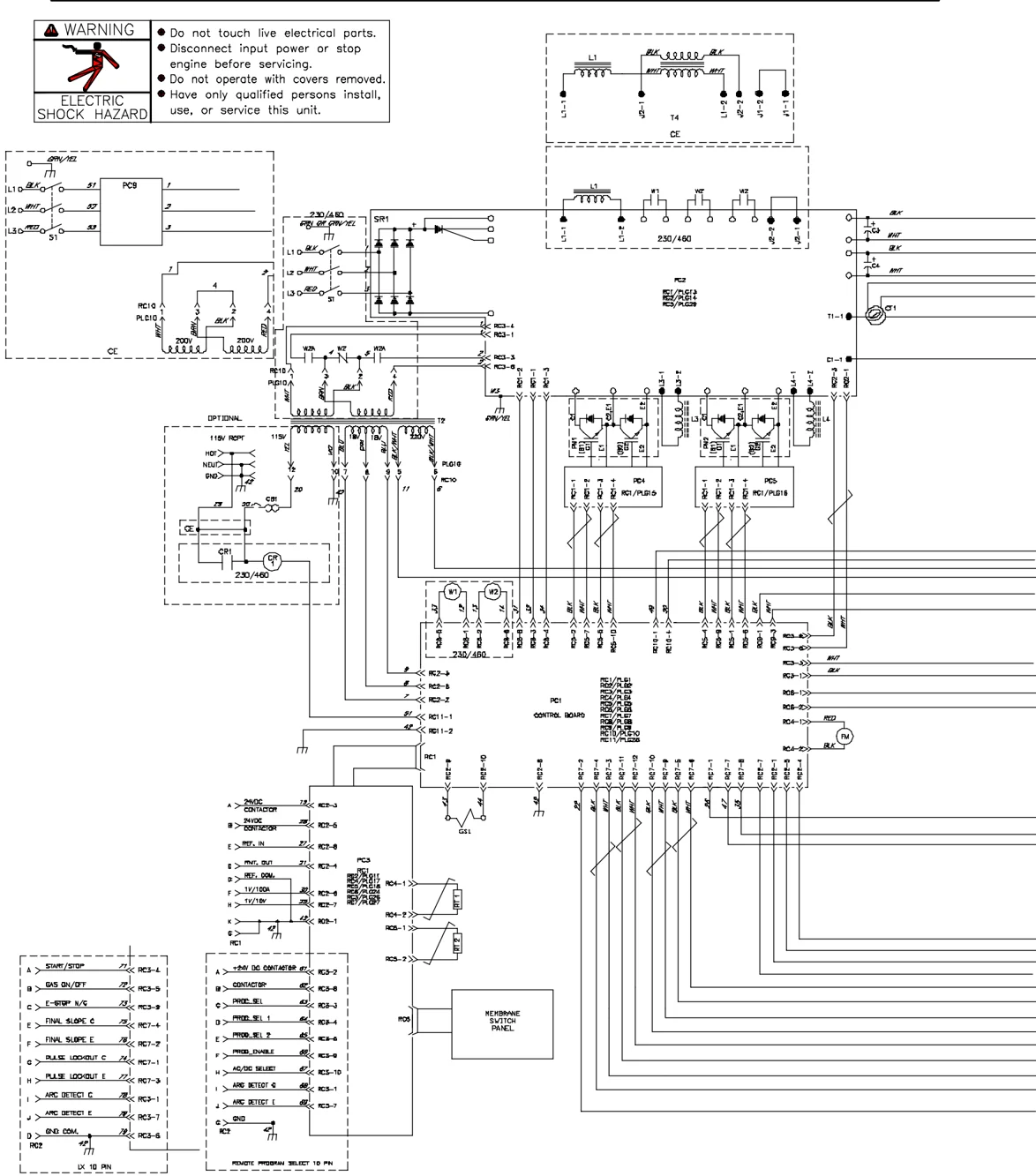
Figure 8-1. Circuit Diagram
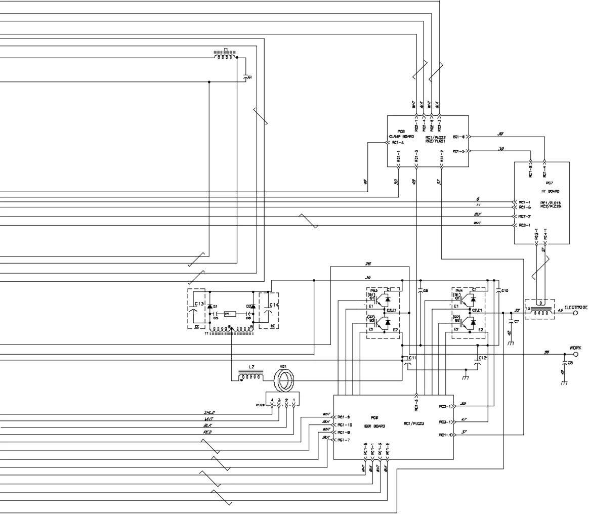
200 321-G
SECTION 9 – HIGH FREQUENCY (HF)
9-1. Welding Processes Requiring High Frequency

1 High-Frequency Voltage TIG – helps arc jump air gap between torch and workpiece and/or stabilize the arc.
9-2. Correct Installation
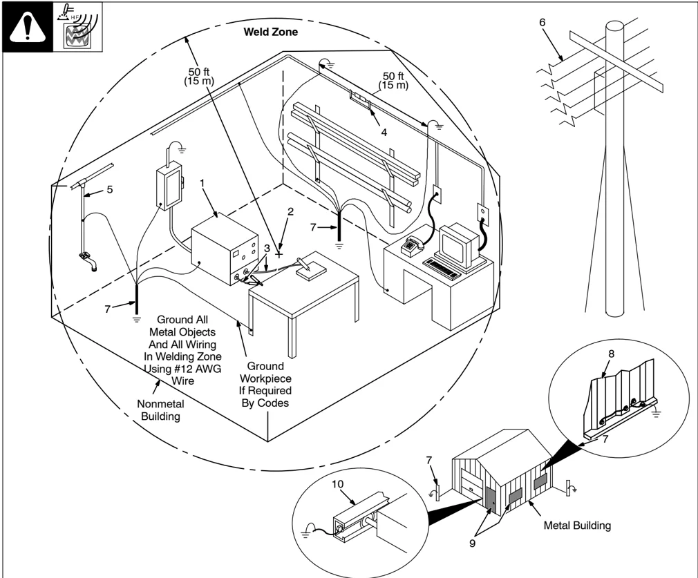
1 HF Source (Welder With Built-In HF Or Separate HF Unit) Ground metal machine case, work output terminal, line disconnect device, input supply, and worktable.
2 Welding Zone And Centerpoint A circle 50 ft (15 m) from centerpoint between HF source and welding torch in all directions.
3 Weld Output Cables Keep cables short and close together.
4 Conduit Joint Bonding And Grounding Electrically join (bond) all conduit sections using copper straps or braided wire. Ground conduit every 50 ft (15 m).
5 Water Pipes And Fixtures Ground water pipes every 50 ft (15 m).
6 External Power Or Telephone Lines Locate HF source at least 50 ft (15 m) away from power and phone lines.
7 Grounding Rod Consult the National Electrical Code for specifications.
8 Metal Building Panel Bonding Methods Bolt or weld building panels together, install copper straps or braided wire across seams, and ground frame.
9 Windows And Doorways Cover all windows and doorways with grounded copper screen of not more than 1/4 in (6.4 mm) mesh.
10 Overhead Door Track Ground the track.
SECTION 10 – SELECTING AND PREPARING TUNGSTEN ELECTRODE FOR DC OR AC WELDING
ac/dc_gtaw 2/2003
⚠️ ▲ Whenever possible and practical, use DC weld output instead of AC weld output.
10-1. Selecting Tungsten Electrode (Wear Clean gloves To Prevent Contamination Of Tungsten)
| Electrode Diameter | Amperage Range - Gas Type♦ - Polarity | |
|---|---|---|
| (DCEN) – ArgonDirect Current Electrode Negative | AC – Argon65% Electrode Negative | |
| 2% Ceria (Orange Band), 1.5% Lanthanum (Gray Band), Or 2% Thorium (Red Band) Alloy Tungstens | ||
| .040” (1 mm) | 25-85 | 20-80 |
| □/□□” (1.6 mm) | 50-160 | 50-150 |
| □/□□” (2.4 mm) | 135-235 | 130-250 |
| □/□” (3.2 mm) | 250-400 | 225-360 |
♦ Typical argon shielding gas flow rates are 11 to 35 cfh (cubic feet per hour).
Figures listed are a guide and are a composite of recommendations from American Welding Society (AWS) and electrode manufacturers.
10-2. Preparing Tungsten Electrode For Welding
⚠️ ▲ Grinding the tungsten electrode produces dust and flying sparks which can cause injury and start fires. Use local exhaust (forced ventilation) at the grinder or wear an approved respirator. Read MSDS for safety information. Consider using tungsten containing ceria, lanthana, or yttria instead of thoria. Grinding dust from thoriated electrodes contains low-level radioactive material. Properly dispose of grinder dust in an environmentally safe way. Wear proper face, hand, and body protection. Keep flammables away.
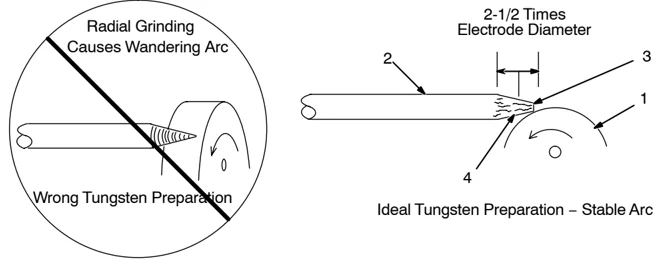
A. Preparing Tungsten For DC Electrode Negative (DCEN) Welding Or AC Welding With Inverter Machines

- Grinding WheelGrind end of tungsten on fine grit, hard abrasive wheel before welding. Do not use wheel for other jobs or tungsten can become contaminated causing lower weld quality.
- Tungsten Electrode
- FlatDiameter of this flat determines amperage capacity.
- Straight GroundGrind lengthwise, not radial.
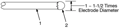
B. Preparing Tungsten For Conventional AC Welding

- Tungsten Electrode
- Balled EndBall end of tungsten by applying AC amperage recommended for a given electrode diameter (see Section 10-1). Let ball on end of the tungsten take its own shape.
SECTION 11 – GUIDELINES FOR TIG WELDING (GTAW)
11-1. Typical GTAW Set-Ups
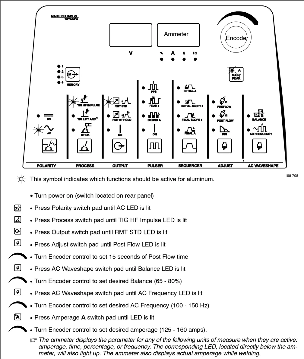
A. AC – GTAW 1/8 in. Aluminum Set-Up

This symbol indicates which functions should be active for aluminum.
- Turn power on (switch located on rear panel)
- Press Polarity switch pad until AC LED is lit
- Press Process switch pad until TIG HF Impulse LED is lit
- Press Output switch pad until RMT STD LED is lit
- Press Adjust switch pad until Post Flow LED is lit
- Turn Encoder control to set 15 seconds of Post Flow time
- Press AC Waveshape switch pad until Balance LED is lit
- Turn Encoder control to set desired Balance (65 - 80%)
- Press AC Waveshape switch pad until AC Frequency LED is lit
- Turn Encoder control to set desired AC Frequency (100 - 150 Hz)
- Press Amperage A switch pad until LED is lit
- Turn Encoder control to set desired amperage (125 - 160 amps).
The ammeter displays the parameter for any of the following units of measure when they are active: amperage, time, percentage, or frequency. The corresponding LED, located directly below the ammeter, will also light up. The ammeter also displays actual amperage while welding.
B. DC - GTAW 16 Gauge Stainless Steel Set-Up
 MADE IN USA
Ammeter
V
% A S Hz
Encoder
1
2
3
4
MEMORY
TIG HF IMPULSE
TIG LIFT ARC™
STICK
RMT STD
RMT 2T HOLD
ON
PPS
PEAK t
BKGDN A
ON
INITIAL A
INITIAL SLOPE t
FINAL SLOPE t
FINAL A
PREFLOW
POST FLOW
DNG
BALANCE
AC FREQUENCY
MAIN/ PEAK
POLARITY PROCESS OUTPUT PULSER SEQUENCER ADJUST AC WAVESHAPE
198 708
This symbol indicates which functions should be active for stainless steel.
• Turn power on (switch located on rear panel) • Press Polarity switch pad until DC LED is lit • Press Process switch pad until TIG HF Impulse LED is lit • Press Output switch pad until RMT STD LED is lit • Press Adjust switch pad until Post Flow LED is lit • Turn Encoder control to set 8 seconds of Post Flow time • Press Amperage A switch pad until LED is lit • Turn Encoder control to set desired amperage (50 - 80 amps).
The ammeter displays the parameter for any of the following units of measure when they are active: amperage, time, percentage, or frequency. The corresponding LED, located directly below the ammeter, will also light up. The ammeter also displays actual amperage while welding.
11-2. Positioning The Torch
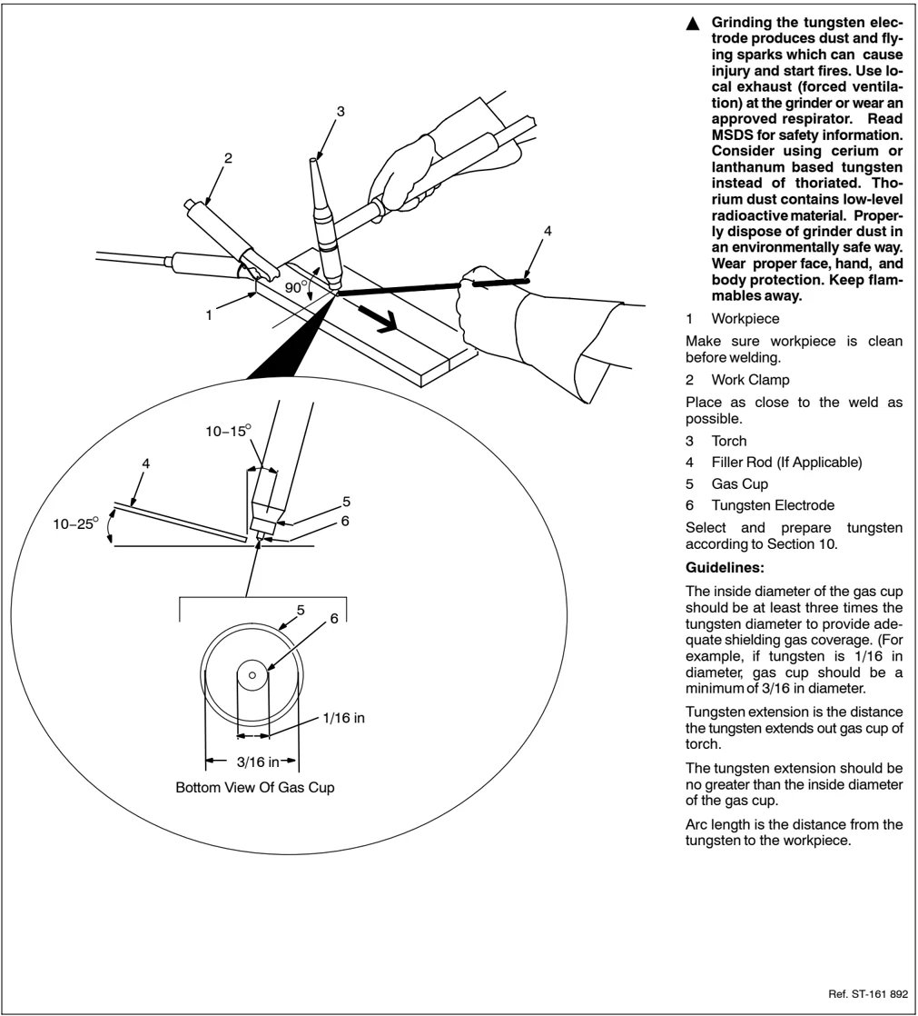
▲ Grinding the tungsten electrode produces dust and flying sparks which can cause injury and start fires. Use local exhaust (forced ventilation) at the grinder or wear an approved respirator. Read MSDS for safety information. Consider using cerium or lanthanum based tungsten instead of thoriated. Thorium dust contains low-level radioactive material. Properly dispose of grinder dust in an environmentally safe way. Wear proper face, hand, and body protection. Keep flammables away.
1 Workpiece Make sure workpiece is clean before welding.
2 Work Clamp Place as close to the weld as possible.
3 Torch
4 Filler Rod (If Applicable)
5 Gas Cup
6 Tungsten Electrode Select and prepare tungsten according to Section 10.
Guidelines: The inside diameter of the gas cup should be at least three times the tungsten diameter to provide adequate shielding gas coverage. (For example, if tungsten is 1/16 in diameter, gas cup should be a minimum of 3/16 in diameter.
Tungsten extension is the distance the tungsten extends out gas cup of torch.
The tungsten extension should be no greater than the inside diameter of the gas cup.
Arc length is the distance from the tungsten to the workpiece.
Ref. ST-161 892
11-3. Lift-Arc™ And HF TIG Start Procedures
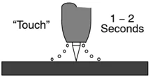
 Lift-Arc Start Method
1
2
"Touch"
1 – 2 Seconds
Do NOT Strike Like A Match!
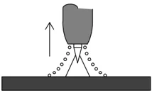
Lift-Arc Start When Lift-Arc™ button light is On, start arc as follows: 1 TIG Electrode 2 Workpiece
Touch tungsten electrode to workpiece at weld start point, enable output and shielding gas with torch trigger, foot control, or hand control. Hold electrode to workpiece for 1-2 seconds, and slowly lift electrode. Arc is formed when electrode is lifted.
Normal open-circuit voltage is not present before tungsten electrode touches workpiece; only a low sensing voltage is present between electrode and workpiece. The solid-state output contactor does not energize until after electrode is touching workpiece. This allows electrode to touch workpiece without overheating, sticking, or getting contaminated.
Application: Lift-Arc is used for the DCEN or AC GTAW process when HF Start method is not permitted, or to replace the scratch method.
HF Start When HF Start button light is On, start arc as follows:
High frequency turns on to help start arc when output is enabled. High frequency turns off when arc is started, and turns on whenever arc is broken to help restart arc.
Application: HF start is used for the DCEN GTAW process when a non-contact arc starting method is required.
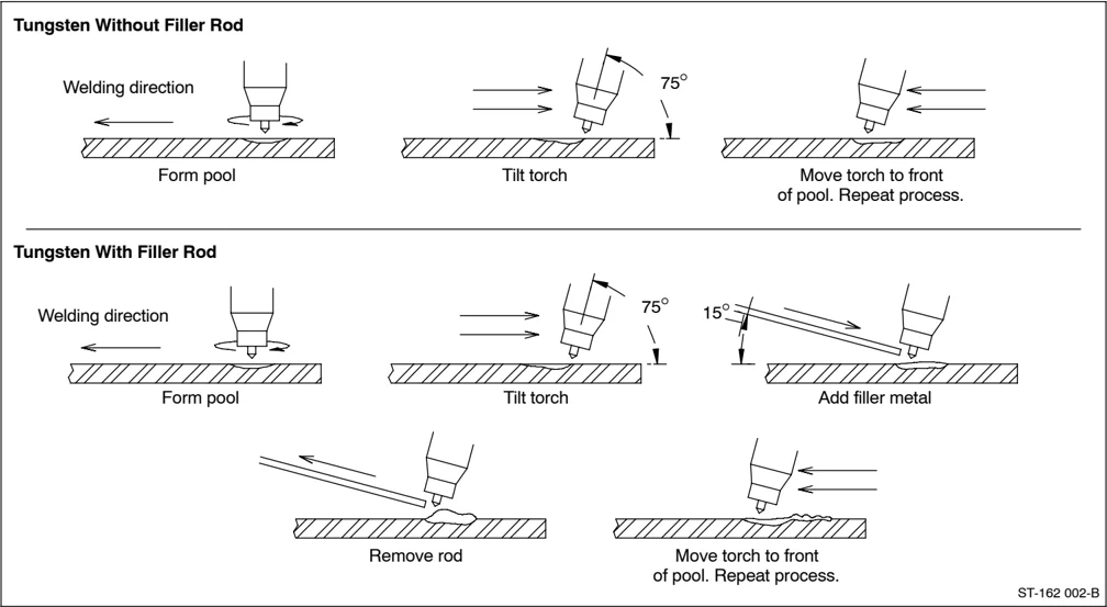
11-4. Torch Movement During Welding
Tungsten Without Filler Rod
Welding direction Form pool
75° Tilt torch
Move torch to front of pool. Repeat process.
Tungsten With Filler Rod
Welding direction Form pool
75° Tilt torch
15° Add filler metal
Remove rod
Move torch to front of pool. Repeat process.
ST-162 002-B
11-5. Positioning Torch Tungsten For Various Weld Joints
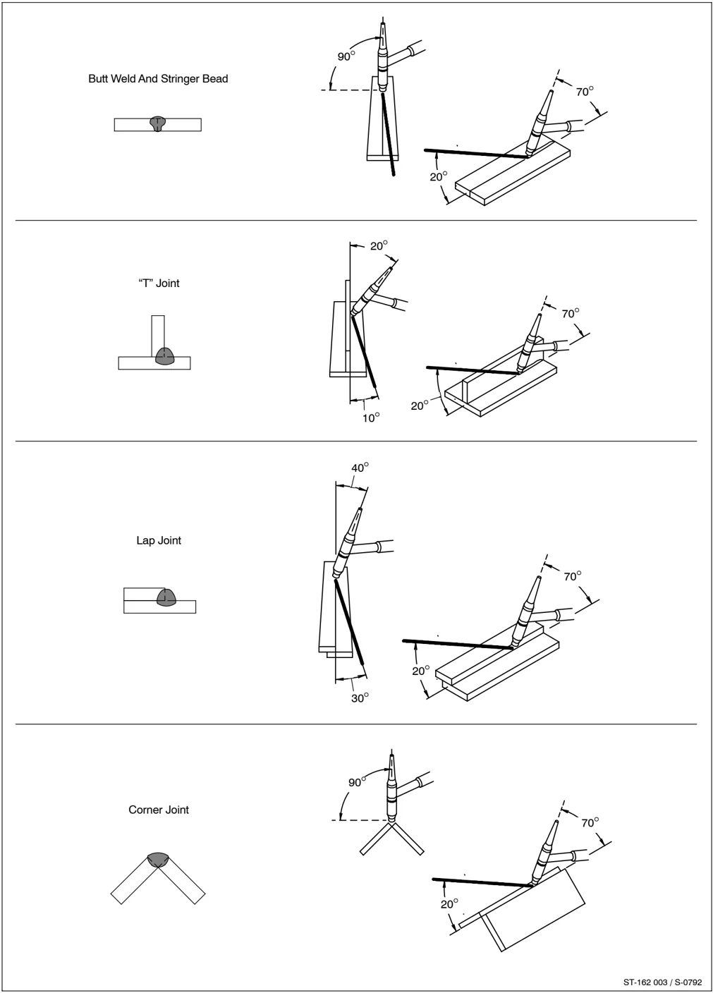
ST-162 003 / S-0792
SECTION 12 – STICK WELDING (SMAW) GUIDELINES
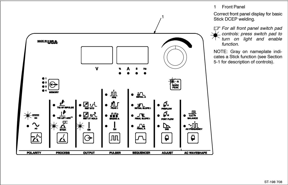
12-1. Front Panel Display For Stick DCEP (Direct Current Electrode Positive)

1 Front Panel Correct front panel display for basic Stick DCEP welding.
For all front panel switch pad controls: press switch pad to turn on light and enable function.
NOTE: Gray on nameplate indicates a Stick function (see Section 5-1 for description of controls).
ST-198 708
12-2. Electrode and Amperage Selection Chart
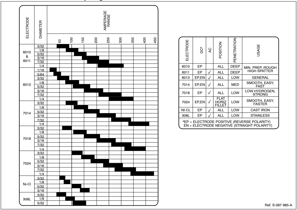
Ref. S-087 985-A
12-3. Stick Welding Procedure
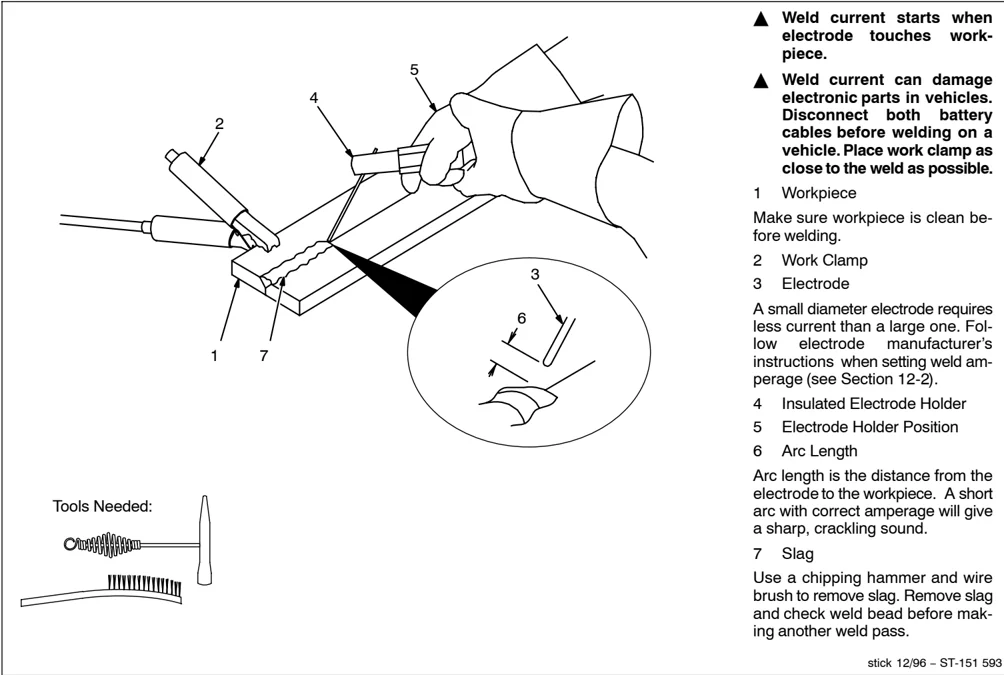
Tools Needed:
▲ Weld current starts when electrode touches workpiece.
▲ Weld current can damage electronic parts in vehicles. Disconnect both battery cables before welding on a vehicle. Place work clamp as close to the weld as possible.
1 Workpiece Make sure workpiece is clean before welding. 2 Work Clamp 3 Electrode A small diameter electrode requires less current than a large one. Follow electrode manufacturer's instructions when setting weld amperage (see Section 12-2). 4 Insulated Electrode Holder 5 Electrode Holder Position 6 Arc Length Arc length is the distance from the electrode to the workpiece. A short arc with correct amperage will give a sharp, crackling sound. 7 Slag Use a chipping hammer and wire brush to remove slag. Remove slag and check weld bead before making another weld pass.
stick 12/96 – ST-151 593
12-4. Striking an Arc – Scratch Start Technique
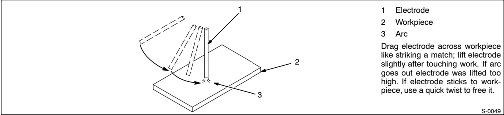
1 Electrode 2 Workpiece 3 Arc Drag electrode across workpiece like striking a match; lift electrode slightly after touching work. If arc goes out electrode was lifted too high. If electrode sticks to workpiece, use a quick twist to free it.
S-0049
12-5. Striking an Arc – Tapping Technique
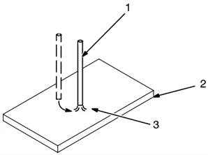
1 Electrode 2 Workpiece 3 Arc Bring electrode straight down to workpiece; then lift slightly to start arc. If arc goes out, electrode was lifted too high. If electrode sticks to workpiece, use a quick twist to free it.
S-0050
12-6. Positioning Electrode Holder
 90° 90°
End View of Work Angle
10°-30° Side View of Electrode Angle
GROOVE WELDS
45° 45° End View of Work Angle
10°-30° Side View of Electrode Angle
FILLET WELDS
S-0060
12-7. Poor Weld Bead Characteristics
 1
2 3
4
5
1 Large Spatter Deposits 2 Rough, Uneven Bead 3 Slight Crater During Welding 4 Bad Overlap 5 Poor Penetration
S-0053-A
12-8. Good Weld Bead Characteristics
 1
2 3
4 5
1 Fine Spatter 2 Uniform Bead 3 Moderate Crater During Welding
Weld a new bead or layer for each 1/8 in. (3.2 mm) thickness in metals being welded.
4 No Overlap 5 Good Penetration into Base Metal
S-0052-B
12-9. Conditions That Affect Weld Bead Shape
NOTE Weld bead shape is affected by electrode angle, arc length, travel speed, and thickness of base metal.
 S-0061
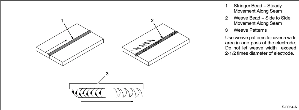
12-10. Electrode Movement During Welding
NOTE Normally, a single stringer bead is satisfactory for most narrow groove weld joints; however, for wide groove weld joints or bridging across gaps, a weave bead or multiple stringer beads work better.
 1 Stringer Bead – Steady Movement Along Seam
2 Weave Bead – Side to Side Movement Along Seam
3 Weave Patterns
Use weave patterns to cover a wide area in one pass of the electrode. Do not let weave width exceed 2-1/2 times diameter of electrode.
S-0054-A
12-11. Butt Joints
 1 Tack Welds
Prevent edges of joint from drawing together ahead of electrode by tack welding the materials in position before final weld.
2 Square Groove Weld
Good for materials up to 3/16 in (5 mm) thick.
3 Single V-Groove Weld
Good for materials 3/16 – 3/8 in (5-9 mm) thick. Cut bevel with oxyacetylene or plasma cutting equipment. Remove scale from material after cutting. A grinder can also be used to prepare bevels.
Create 30 degree angle of bevel on materials in V-groove welding.
4 Double V-Groove Weld
Good for materials thicker than 3/8 in (9 mm).
S-0662
12-12. Lap Joint
 1 Electrode
2 Single-Layer Fillet Weld
Move electrode in circular motion.
3 Multi-Layer Fillet Weld
Weld a second layer when a heavier fillet is needed. Remove slag before making another weld pass. Weld both sides of joint for maximum strength.
S-0063 / S-0064
12-13. Tee Joint
 1 Electrode
2 Fillet Weld
Keep arc short and move at definite rate of speed. Hold electrode as shown to provide fusion into the corner. Square edge of the weld surface.
For maximum strength weld both sides of upright section.
3 Multi-Layer Deposits
Weld a second layer when a heavier fillet is needed. Use any of the weaving patterns shown in Section 12-10. Remove slag before making another weld pass.
S-0060 / S-0058-A / S-0061
12-14. Weld Test
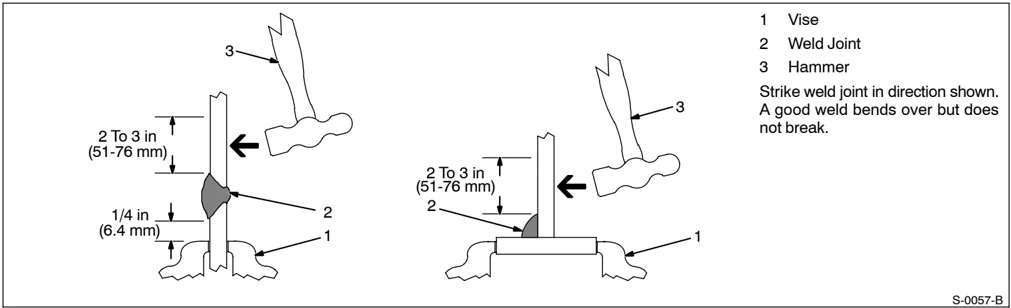
1 Vise 2 Weld Joint 3 Hammer
Strike weld joint in direction shown. A good weld bends over but does not break.
S-0057-B
12-15. Troubleshooting – Porosity
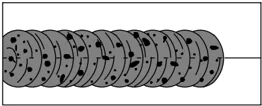
Porosity – small cavities or holes resulting from gas pockets in weld metal.
| Possible Causes | Corrective Actions |
|---|---|
| Arc length too long. | Reduce arc length. |
| Damp electrode. | Use dry electrode. |
| Workpiece dirty. | Remove all grease, oil, moisture, rust, paint, coatings, slag, and dirt from work surface before welding. |
12-16. Troubleshooting – Excessive Spatter
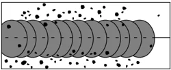
Excessive Spatter – scattering of molten metal particles that cool to solid form near weld bead.
| Possible Causes | Corrective Actions |
|---|---|
| Amperage too high for electrode. | Decrease amperage or select larger electrode. |
| Arc length too long or voltage too high. | Reduce arc length or voltage. |
12-17. Troubleshooting – Incomplete Fusion
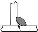
Incomplete Fusion – failure of weld metal to fuse completely with base metal or a preceeding weld bead.
| Possible Causes | Corrective Actions |
|---|---|
| Insufficient heat input. | Increase amperage. Select larger electrode and increase amperage. |
| Improper welding technique. | Place stringer bead in proper location(s) at joint during welding. |
| Adjust work angle or widen groove to access bottom during welding. | |
| Momentarily hold arc on groove side walls when using weaving technique. | |
| Keep arc on leading edge of weld puddle. | |
| Workpiece dirty. | Remove all grease, oil, moisture, rust, paint, coatings, slag, and dirt from work surface before welding. |
12-18. Troubleshooting – Lack Of Penetration
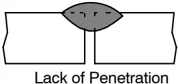
Lack Of Penetration – shallow fusion between weld metal and base metal.
| Possible Causes | Corrective Actions |
|---|---|
| Improper joint preparation. | Material too thick. Joint preparation and design must provide access to bottom of groove. |
| Improper weld technique. | Keep arc on leading edge of weld puddle. |
| Insufficient heat input. | Increase amperage. Select larger electrode and increase amperage. |
| Reduce travel speed. |
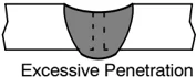
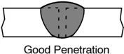
12-19. Troubleshooting – Excessive Penetration
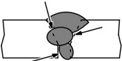
Excessive Penetration – weld metal melting through base metal and hanging underneath weld.
| Possible Causes | Corrective Actions |
|---|---|
| Excessive heat input. | Select lower amperage. Use smaller electrode. |
| Increase and/or maintain steady travel speed. |
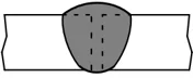
12-20. Troubleshooting – Burn-Through
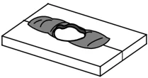
Burn-Through – weld metal melting completely through base metal resulting in holes where no metal remains.
| Possible Causes | Corrective Actions |
|---|---|
| Excessive heat input. | Select lower amperage. Use smaller electrode. |
| Increase and/or maintain steady travel speed. |
12-21. Troubleshooting – Waviness Of Bead
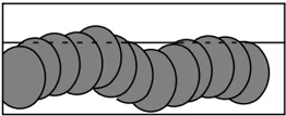
Waviness Of Bead – weld metal that is not parallel and does not cover joint formed by base metal.
| Possible Causes | Corrective Actions |
|---|---|
| Unsteady hand. | Use two hands. Practice technique. |
12-22. Troubleshooting – Distortion
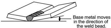
Distortion – contraction of weld metal during welding that forces base metal to move.
Base metal moves in the direction of the weld bead.
| Possible Causes | Corrective Actions |
|---|---|
| Excessive heat input. | Use restraint (clamp) to hold base metal in position. |
| Make tack welds along joint before starting welding operation. | |
| Select lower amperage for electrode. | |
| Increase travel speed. | |
| Weld in small segments and allow cooling between welds. |
Notes
SECTION 13 – PARTS LIST
Hardware is common and not available unless listed.
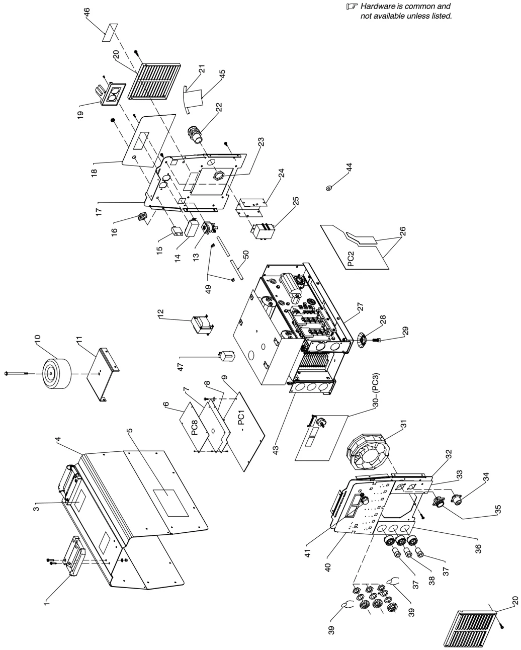
Figure 13-1. Main Assembly
ST-801 870-L
| Item No. | Dia. Mkgs. | Part No. | Description | Quantity Model | |
|---|---|---|---|---|---|
| □□□/□□□ | 400 CE |
Figure 13-1. Main Assembly
| Item No. | Dia. Mkgs. | Part No. | Description | Quantity Model | |
|---|---|---|---|---|---|
| 230/460 | 400 CE | ||||
| 1 | 206 108 | HANDLE, rubberized carrying | 2 | 2 | |
| 3 | 138 442 | LABEL, caution falling | 2 | ||
| 3 | 179 309 | LABEL, caution falling | 2 | ||
| 4 | +175 148 | WRAPPER | 1 | 1 | |
| 175 256 | INSULATOR, side RH & LH | 2 | 2 | ||
| 5 | 134 327 | LABEL, warning general precautionary | 2 | ||
| 5 | 179 310 | LABEL, warning general precautionary | 2 | ||
| 6 | PC8 | 206 261 | CIRCUIT CARD ASSEMBLY, clamp | 1 | 1 |
| PLG21 | 115 094 | CONNECTOR & SOCKETS | 1 | 1 | |
| PLG22 | 115 093 | CONNECTOR & SOCKETS | 1 | 1 | |
| 7 | 183 613 | INSULATOR, PC card clamp | 1 | 1 | |
| 8 | 182 498 | BRACKET, mtg PC card clamp | 1 | ||
| 9 | PC1 | 211 242 | CIRCUIT CARD ASSEMBLY, control | 1 | |
| 9 | PC1 | 211 239 | CIRCUIT CARD ASSEMBLY, control | 1 | |
| PLG2 | 115 091 | CONNECTOR & SOCKETS | 1 | 1 | |
| PLG3 | 115 092 | CONNECTOR & SOCKETS | 1 | 1 | |
| PLG4 | 131 054 | CONNECTOR & SOCKETS | 1 | 1 | |
| PLG5 | 115 091 | CONNECTOR & SOCKETS | 1 | 1 | |
| PLG7 | 130 203 | CONNECTOR & SOCKETS | 1 | 1 | |
| PLG8 | 115 092 | CONNECTOR & SOCKETS | 1 | 1 | |
| PLG9 | 131 204 | CONNECTOR & SOCKETS | 1 | 1 | |
| PLG10 | 115 094 | CONNECTOR & SOCKETS | 1 | 1 | |
| 10 | T2 | ◆193 311 | TRANSFORMER, control | 1 | |
| 10 | T2 | ◆193 310 | TRANSFORMER, control | 1 | |
| 11 | ◆187 461 | BRACKET, mtg aux transformer | 1 | ||
| 12 | T2 | 189 536 | TRANSFORMER, control | 1 | |
| 12 | T2 | 180 873 | TRANSFORMER, control | 1 | |
| RC10 | 166 679 | CONNECTOR & SOCKETS | 1 | 1 | |
| PLG10 | 166 680 | CONNECTOR & PINS | 1 | 1 | |
| 13 | GS1 | 133 873 | VALVE, 24VDC 2way | 1 | 1 |
| 14 | ◆189 033 | RECEPTACLE, str dx grd 2P 3W 15A | 1 | 1 | |
| 15 | CB1 | ◆083 432 | SUPPLEMENTARY PROTECTOR, 1P 10A 250VAC | 1 | |
| 15 | CB1 | ◆161 078 | SUPPLEMENTARY PROTECTOR, 1P 7A 250VAC | 1 | |
| 16 | 605 227 | NUT, .750-14 knurled | 1 | 1 | |
| 17 | 182 205 | PANEL, rear | 1 | 1 | |
| 18 | PLATE, identification rear | ||||
| (order by model and serial number) | 1 | 1 | |||
| 19 | ◆175 282 | COVER, receptacle | 1 | 1 | |
| 20 | 175 138 | BOX, louver | 2 | 2 | |
| 21 | 182 561 | CABLE, pwr | 1 | 1 | |
| 22 | 201 155 | BUSHING, strain relief .450/.709 ID | 1 | 1 | |
| 23 | 198 245 | NUT, stl locking | 1 | 1 | |
| 24 | 176 226 | INSULATOR, switch power | 1 | 1 | |
| 25 | S1 | 128 756 | SWITCH, tgl 3PST 40A 600VAC (Power Switch) | 1 | 1 |
| 26 | PC2 | 213 198 | KIT, interconnecting replacement | 1 | 1 |
| 176 879 | SCREW, M5–.8–2 | 18 | 18 | ||
| PLG13 | 131 204 | CONNECTOR & SOCKETS | 1 | 1 | |
| PLG14 | 115 094 | CONNECTOR & SOCKETS | 1 | 1 | |
| 179 626 | BUS BAR, interconnecting | 1 | 1 | ||
| 27 | +208 471 | BASE | 1 | 1 | |
| 28 | 173 693 | FOOT, mtg unit | 4 | 4 | |
| 29 | 176 736 | SCREW, mtg foot | 4 | 4 | |
| 30 | PC3 | 224 480 | CIRCUIT CARD, front panel (DX and SD models) (includes) | 1 | 1 |
| 30 | PC3 | 224 481 | CIRCUIT CARD, front panel (LX models) (includes) | 1 | 1 |
| DD1-6 | 186 914 | LED | 6 | 6 | |
| PLG17, 18 | 131 054 | CONNECTOR & SOCKETS | 1 | 1 |
| Item No. | Dia. Mkgs. | Part No. | Description | Quantity Model | |
|---|---|---|---|---|---|
| 230/460 | 400 CE |
Figure 13-1. Main Assembly (Continued)
| PLG26 | 115 091 | CONNECTOR & SOCKETS | 1 | 1 | |
|---|---|---|---|---|---|
| PLG11 | 115 092 | RECEPTACLE, w/leads & plug | 1 | 1 | |
| 31 | FM | 175 084 | MOTOR, fan 24VDC 3000RPM | 1 | 1 |
| 135 635 | CONNECTOR & SOCKETS | 1 | 1 | ||
| 32 | 200 320 | PANEL, front | 1 | 1 | |
| 33 | 191 173 | NAMEPLATE, RH | 1 | 1 | |
| 33 | 191 172 | NAMEPLATE, RH W/Optional 10-pin Installed (LX models) | 1 | 1 | |
| 34 | RC2 | ◆191 302 | CONNECTOR & SOCKETS | 1 | 1 |
| 34 | RC2 | ◆197 181 | CONNECTOR & SOCKETS (LX models) | 1 | 1 |
| 35 | RC1 | 188 186 | CONNECTOR & SOCKETS | 1 | 1 |
| 36 | 192 018 | NAMEPLATE, LH | 1 | 1 | |
| 37 | 202 813 | RECEPTACLE, twist lock power assembly (female) | 2 | 2 | |
| 38 | 202 810 | RECEPTACLE, gas panel mount (male) | 1 | ||
| 38 | 202 815 | RECEPTACLE, gas panel mount (female) | 1 | ||
| 39 | C7,8 | 186 543 | CAPACITOR ASSEMBLY | 2 | 2 |
| 40 | 198 707 | MEMBRANE PANEL (DX, LX models) | 1 | ||
| 40 | 198 710 | MEMBRANE PANEL (SD models) | 1 | ||
| 40 | 198 713 | MEMBRANE PANEL (DX, LX, CE models) | 1 | ||
| 40 | 198 715 | MEMBRANE PANEL (SD CE models) | 1 | ||
| 41 | 174 991 | KNOB, encoder | 1 | 1 | |
| 43 | Fig13-2 | WINDTUNNELS w/COMPONENTS | 1 | 1 | |
| 44 | T4 | 182 108 | CHOKE | 1 | |
| 45 | 182 826 | LABEL, warning electric shock power cord | 1 | ||
| 46 | 148 329 | LABEL, caution incorrect voltage | 1 | ||
| 47 | ◆059 266 | RELAY, encl 120 VAC DPDT 10A/120VAC 8-Pin Flange Mtg | 1 | ||
| 49 | 089 120 | CLAMP, hose .375 – .450 clp dia | 2 | 2 | |
| 50 | 188 048 | HOSE, nprn brd no.1 x .250 ID x 18.00 | 1 | 1 |
+When ordering a component originally displaying a precautionary label, the label should also be ordered.
◆Optional
To maintain the factory original performance of your equipment, use only Manufacturer’s Suggested Replacement Parts. Model and serial number required when ordering parts from your local distributor.
Hardware is common and not available unless listed.
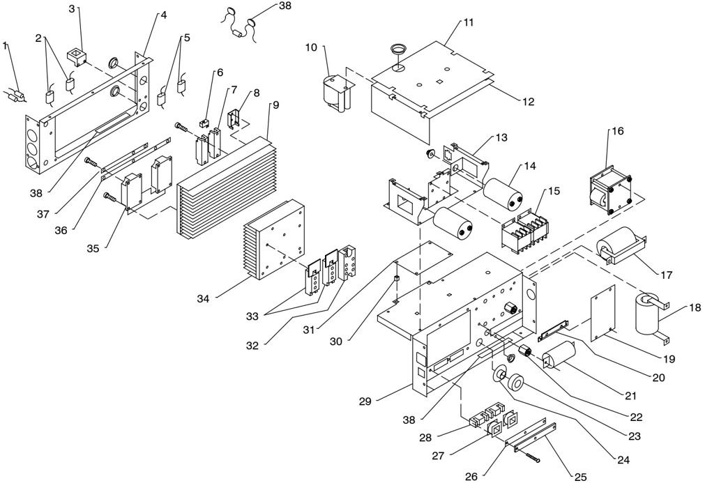
Figure 13-2. Windtunnels w/Components
ST-801 871-F
| Item No. | Dia. Mkgs. | Part No. | Description | Quantity Model | |
|---|---|---|---|---|---|
| 230/460 | 400 CE | ||||
| Figure 13-2. Windtunnels w/Components (Fig 13-1 Item 43) | |||||
| 1 | C11,12 | 185 424 | CAPACITOR, filter assembly | 1 | 1 |
| 2 | C9,10 | 201 391 | CAPACITOR, polyp met film 1uf 600VDC | 2 | 2 |
| 3 | HD1 | 182 918 | TRANSDUCER, current 400A | 1 | 1 |
| 4 | +182 206 | WINDTUNNEL, LH | 1 | 1 | |
| 5 | 185 424 | CAPACITOR, filter assembly | 2 | ||
| 6 | R1,C5,6 | 175 194 | RESISTOR/CAPACITOR | 1 | 1 |
| 7 | D1,2 | 185 775 | KIT, diode | 2 | 2 |
| 8 | 188 361 | HEAT SINK | 2 | 2 | |
| 9 | 182 208 | HEAT SINK | 1 | 1 | |
| 10 | T3 | 182 667 | TRANSFORMER, coupling | 1 | 1 |
| 11 | 183 073 | INSULATOR, PC card HF | 1 | 1 | |
| 12 | 182 499 | ENCLOSURE, HF | 1 | 1 | |
| 13 | 182 806 | BRACKET, mtg contactor/capacitor/PC board | 1 | 1 | |
| 14 | C3,4 | 174 980 | CAPACITOR, elctlt 2700uf 420VDC | 2 | 2 |
| 15 | W1,2,2A | 223 006 | CONTACTOR, w/interlock and standoffs | 1 |
| Item No. | Dia. Mkgs. | Part No. | Description | Quantity Model | |
|---|---|---|---|---|---|
| 230/460 | 400 CE |
Figure 13-2. Windtunnels w/Components
(Fig 13-1 Item 43) (Continued)
| … 16 | T1 | 183 014 | TRANSFORMER, HF | 1 | 1 |
|---|---|---|---|---|---|
| … 17 | L2 | 183 009 | STABILIZER, output | 1 | 1 |
| … 18 | L1 | 187 522 | INDUCTOR, input | 1 | 1 |
| … 19 | PC9 | 187 264 | CIRCUIT CARD ASSEMBLY, input filter | 1 | 1 |
| … 20 | 187 463 | BRACKET | 1 | 1 | |
| … 21 | C1 | 186 549 | CAPACITOR, polyp .27uf 1000VDC | 1 | 1 |
| … 22 | 025 248 | STAND-OFF, insul .250-20 x 1.250 lg | 2 | 2 | |
| … 23 | CT1 | 175 199 | TRANSFORMER, current | 1 | 1 |
| … 24 | 177 547 | BUSHING, snap-in CT-mount | 1 | 1 | |
| … 25 | 175 140 | BRACKET, DI-DT | 1 | 1 | |
| … 26 | 181 197 | GASKET, DI-DT rubber | 1 | 1 | |
| … 27 | L3,4 | 204 685 | COIL, DI-DT | 2 | 2 |
| … 28 | 109 056 | CORE | 2 | 2 | |
| … 29 | +187 460 | WINDTUNNEL, RH | 1 | 1 | |
| … 30 | 141 690 | GROMMET, scr No. 8/10 | 4 | 4 | |
| … 31 | PC7 | 189 135 | CIRCUIT CARD, HF (includes) | 1 | 1 |
| F1 | 012 633 | FUSE, mintr gl 1A 250V | 1 | 1 | |
| 196 455 | POINT, spark gap | 2 | 2 | ||
| PLG19 | 115 092 | CONNECTOR & SOCKETS | 1 | 1 | |
| PLG20 | 131 054 | CONNECTOR & SOCKETS | 1 | 1 | |
| … 32 | SR1 | 179 629 | KIT, diode | 1 | 1 |
| … 33 | PM1,2/PC4,5 | 179 628 | KIT, transistor IGBT module | 1 | 1 |
| RT1,2 | 173 632 | THERMISTOR, NTC 30K ohm | 2 | 2 | |
| … 34 | 173 631 | HEAT SINK, power module | 1 | 1 | |
| … 35 | PM3,4/PC6 | 206 477 | KIT, IGBT | 1 | 1 |
| PLG23 | 115 091 | CONNECTOR & SOCKETS | 1 | 1 | |
| … 36 | 196 958 | BUS BAR, diode IGBT | 1 | 1 | |
| … 37 | 196 957 | BUS BAR, IGBT | 1 | 1 | |
| … 38 | 185 835 | LABEL, warning exploding parts | 2 | ||
| … 38 | 185 836 | LABEL, warning exploding parts | 2 |
+When ordering a component originally displaying a precautionary label, the label should also be ordered.
To maintain the factory original performance of your equipment, use only Manufacturer’s Suggested Replacement Parts. Model and serial number required when ordering parts from your local distributor.
Warranty Questions? Call 1-800-4-A-MILLER for your local Miller distributor.
Your distributor also gives you ... Service You always get the fast, reliable response you need. Most replacement parts can be in your hands in 24 hours.
Support Need fast answers to the tough welding questions? Contact your distributor. The expertise of the distributor and Miller is there to help you, every step of the way.

TRUE BLUE®
WARRANTY
Effective January 1, 2006 (Equipment with a serial number preface of “LG” or newer)
This limited warranty supersedes all previous Miller warranties and is exclusive with no other guarantees or warranties expressed or implied.
LIMITED WARRANTY – Subject to the terms and conditions below, Miller Electric Mfg. Co., Appleton, Wisconsin, warrants to its original retail purchaser that new Miller equipment sold after the effective date of this limited warranty is free of defects in material and workmanship at the time it is shipped by Miller. THIS WARRANTY IS EXPRESSLY IN LIEU OF ALL OTHER WARRANTIES, EXPRESS OR IMPLIED, INCLUDING THE WARRANTIES OF MERCHANTABILITY AND FITNESS.
Within the warranty periods listed below, Miller will repair or replace any warranted parts or components that fail due to such defects in material or workmanship. Miller must be notified in writing within thirty (30) days of such defect or failure, at which time Miller will provide instructions on the warranty claim procedures to be followed.
Miller shall honor warranty claims on warranted equipment listed below in the event of such a failure within the warranty time periods. All warranty time periods start on the date that the equipment was delivered to the original retail purchaser, or one year after the equipment is sent to a North American distributor or eighteen months after the equipment is sent to an International distributor.
- 5 Years Parts — 3 Years Labor
- Original main power rectifiers
- 3 Years — Parts and Labor
- Transformer/Rectifier Power Sources
- Plasma Arc Cutting Power Sources
- Process Controllers
- Semi-Automatic and Automatic Wire Feeders
- Inverter Power Sources (Unless Otherwise Stated)
- Water Coolant Systems (Integrated)
- Intelligig
- Engine Driven Welding Generators (NOTE: Engines are warranted separately by the engine manufacturer.)
- 1 Year — Parts and Labor Unless Specified
- Motor Driven Guns (w/exception of Spoolmate Spoolguns)
- Positioners and Controllers
- Automatic Motion Devices
- RFCS Foot Controls
- Induction Heating Power Sources, Coolers, and Electronic Controls/Recorders
- Water Coolant Systems (Non-Integrated)
- Flowgauge and Flowmeter Regulators (No Labor)
- HF Units
- Grids
- Spot Welders
- Load Banks
- Arc Stud Power Sources & Arc Stud Guns
- Racks
- Running Gear/Trailers
- Plasma Cutting Torches (except APT & SAF Models)
- Field Options (NOTE: Field options are covered under True Blue® for the remaining warranty period of the product they are installed in, or for a minimum of one year — whichever is greater.)
- Bernard-Branded Mig Guns (No Labor)
- Weldcraft-Branded TIG Torches (No Labor)
- Subarc Wire Drive Assemblies
- 6 Months — Batteries
- 90 Days — Parts
- MIG Guns/TIG Torches and Subarc (SAW) Guns
- Induction Heating Coils and Blankets, Cables, and Non-Electronic Controls
- APT & SAF Model Plasma Cutting Torches
- Remote Controls
- Accessory (Kits)
- Replacement Parts (No labor)
- Spoolmate Spoolguns
- Canvas Covers
Miller’s True Blue® Limited Warranty shall not apply to:
- Consumable components; such as contact tips, cutting nozzles, contactors, brushes, slip rings, relays or parts that fail due to normal wear. (Exception: brushes, slip rings, and relays are covered on Bobcat, Trailblazer, and Legend models.)
- Items furnished by Miller, but manufactured by others, such as engines or trade accessories. These items are covered by the manufacturer’s warranty, if any.
- Equipment that has been modified by any party other than Miller, or equipment that has been improperly installed, improperly operated or misused based upon industry standards, or equipment which has not had reasonable and necessary maintenance, or equipment which has been used for operation outside of the specifications for the equipment.
MILLER PRODUCTS ARE INTENDED FOR PURCHASE AND USE BY COMMERCIAL/INDUSTRIAL USERS AND PERSONS TRAINED AND EXPERIENCED IN THE USE AND MAINTENANCE OF WELDING EQUIPMENT.
In the event of a warranty claim covered by this warranty, the exclusive remedies shall be, at Miller’s option: (1) repair; or (2) replacement; or, where authorized in writing by Miller in appropriate cases, (3) the reasonable cost of repair or replacement at an authorized Miller service station; or (4) payment of or credit for the purchase price (less reasonable depreciation based upon actual use) upon return of the goods at customer’s risk and expense. Miller’s option of repair or replacement will be F.O.B., Factory at Appleton, Wisconsin, or F.O.B. at a Miller authorized service facility as determined by Miller. Therefore no compensation or reimbursement for transportation costs of any kind will be allowed.
TO THE EXTENT PERMITTED BY LAW, THE REMEDIES PROVIDED HEREIN ARE THE SOLE AND EXCLUSIVE REMEDIES. IN NO EVENT SHALL MILLER BE LIABLE FOR DIRECT, INDIRECT, SPECIAL, INCIDENTAL OR CONSEQUENTIAL DAMAGES (INCLUDING LOSS OF PROFIT), WHETHER BASED ON CONTRACT, TORT OR ANY OTHER LEGAL THEORY.
ANY EXPRESS WARRANTY NOT PROVIDED HEREIN AND ANY IMPLIED WARRANTY, GUARANTY OR REPRESENTATION AS TO PERFORMANCE, AND ANY REMEDY FOR BREACH OF CONTRACT TORT OR ANY OTHER LEGAL THEORY WHICH, BUT FOR THIS PROVISION, MIGHT ARISE BY IMPLICATION, OPERATION OF LAW, CUSTOM OF TRADE OR COURSE OF DEALING, INCLUDING ANY IMPLIED WARRANTY OF MERCHANTABILITY OR FITNESS FOR PARTICULAR PURPOSE, WITH RESPECT TO ANY AND ALL EQUIPMENT FURNISHED BY MILLER IS EXCLUDED AND DISCLAIMED BY MILLER.
Some states in the U.S.A. do not allow limitations of how long an implied warranty lasts, or the exclusion of incidental, indirect, special or consequential damages, so the above limitation or exclusion may not apply to you. This warranty provides specific legal rights, and other rights may be available, but may vary from state to state.
In Canada, legislation in some provinces provides for certain additional warranties or remedies other than as stated herein, and to the extent that they may not be waived, the limitations and exclusions set out above may not apply. This Limited Warranty provides specific legal rights, and other rights may be available, but may vary from province to province.
miller_warr 2006-01

Owner's Record
Please complete and retain with your personal records.
| Model Name | Serial/Style Number |
|---|---|
| Purchase Date | (Date which equipment was delivered to original customer.) |
| Distributor | |
| Address | |
| City | |
| State | Zip |
For Service
Contact a DISTRIBUTOR or SERVICE AGENCY near you.
Always provide Model Name and Serial/Style Number.
Contact your Distributor for:
- Welding Supplies and Consumables
- Options and Accessories
- Personal Safety Equipment
- Service and Repair
- Replacement Parts
- Training (Schools, Videos, Books)
- Technical Manuals (Servicing Information and Parts)
- Circuit Diagrams
- Welding Process Handbooks
To locate a Distributor or Service Agency visit www.millerwelds.com or call 1-800-4-A-Miller
Contact the Delivering Carrier to:
- File a claim for loss or damage during shipment.
- For assistance in filing or settling claims, contact your distributor and/or equipment manufacturer’s Transportation Department.
Miller Electric Mfg. Co.
An Illinois Tool Works Company
1635 West Spencer Street
Appleton, WI 54914 USA
International Headquarters–USA
USA Phone: 920-735-4505 Auto-Attended
USA & Canada FAX: 920-735-4134
International FAX: 920-735-4125
European Headquarters – United Kingdom
Phone: 44 (0) 1204-593493
FAX: 44 (0) 1204-598066
www.MillerWelds.com
PRINTED IN USA
© 2006 Miller Electric Mfg. Co. 2006-01