SECTION 6 – ADVANCED FUNCTIONS
6-1. Programmable TIG Start Parameters (Polarity, Amperage And Time)
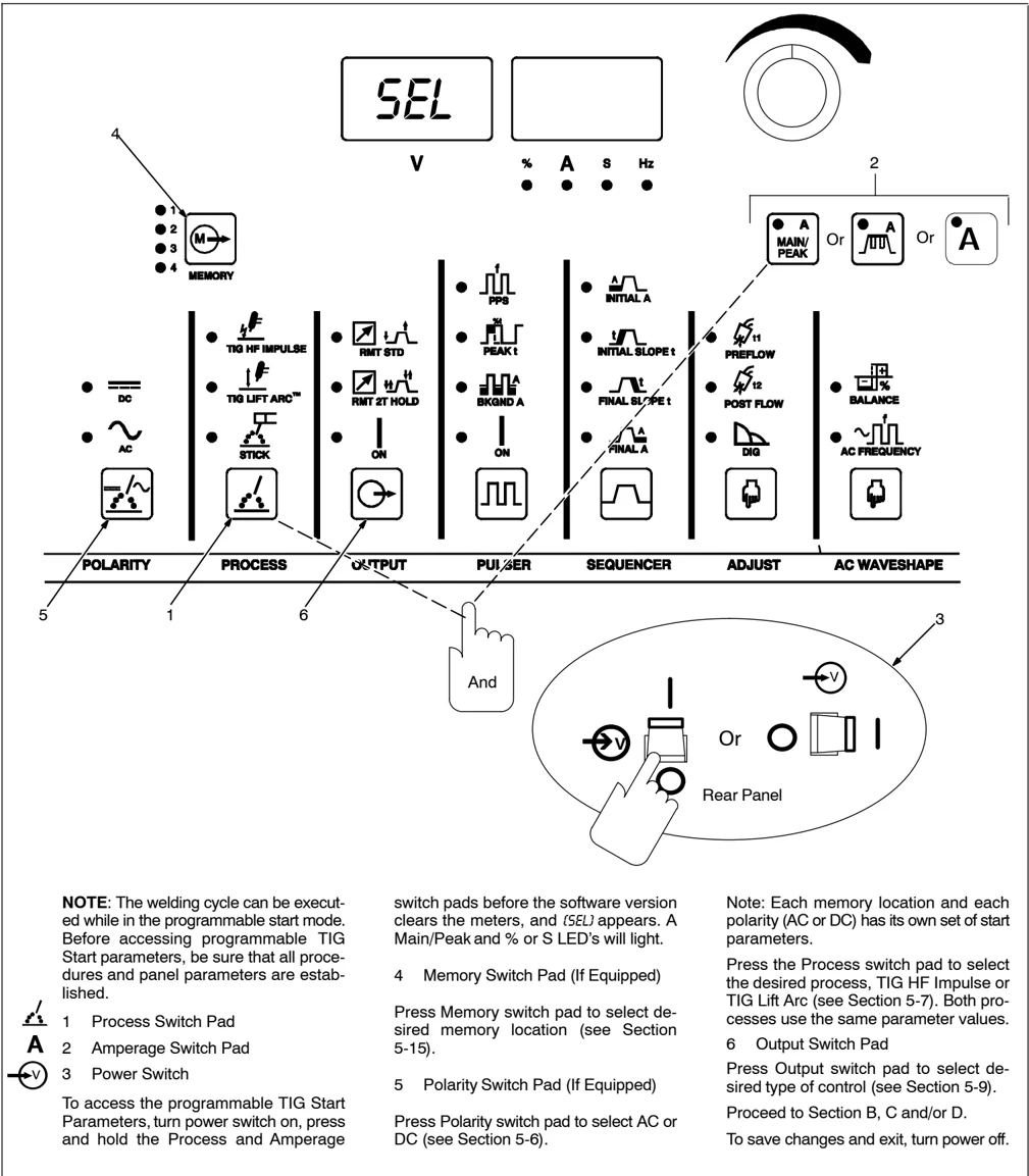
A. Accessing Programmable TIG Start Parameters (All Models)

NOTE: The welding cycle can be executed while in the programmable start mode. Before accessing programmable TIG Start parameters, be sure that all procedures and panel parameters are established.
- Process Switch Pad
- Amperage Switch Pad
- Power Switch
To access the programmable TIG Start Parameters, turn power switch on, press and hold the Process and Amperage switch pads before the software version clears the meters, and SEL appears. A Main/Peak and % or S LED’s will light.
- Memory Switch Pad (If Equipped)
Press Memory switch pad to select desired memory location (see Section 5-15).
- Polarity Switch Pad (If Equipped)
Press Polarity switch pad to select AC or DC (see Section 5-6).
Note: Each memory location and each polarity (AC or DC) has its own set of start parameters.
Press the Process switch pad to select the desired process, TIG HF Impulse or TIG Lift Arc (see Section 5-7). Both processes use the same parameter values.
- Output Switch Pad
Press Output switch pad to select desired type of control (see Section 5-9). Proceed to Section B, C and/or D.
To save changes and exit, turn power off.
B. Changing Programmable TIG Start Polarity (Dynasty Models Only)
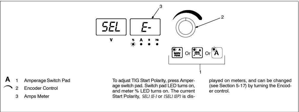
A 1 Amperage Switch Pad 2 Encoder Control 3 Amps Meter
To adjust TIG Start Polarity, press Amperage switch pad. Switch pad LED turns on, and meter % LED turns on. The current Start Polarity, SEL {E-} or {SEL} {EP} is displayed on meters, and can be changed (see Section 5-17) by turning the Encoder control.
C. Changing Programmable TIG Start Amperage (All Models)
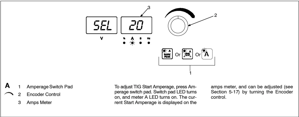
A 1 Amperage Switch Pad 2 Encoder Control 3 Amps Meter
To adjust TIG Start Amperage, press Amperage switch pad. Switch pad LED turns on, and meter A LED turns on. The current Start Amperage is displayed on the amps meter, and can be adjusted (see Section 5-17) by turning the Encoder control.
D. Changing Programmable Start Time (All Models)
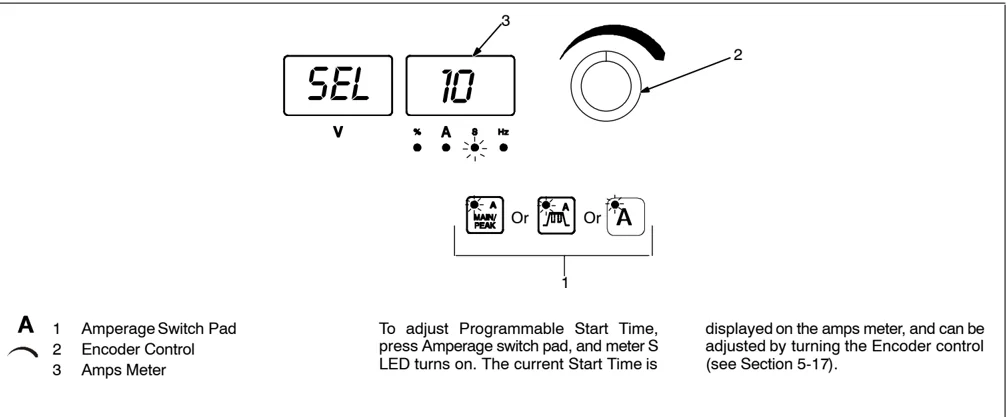
A 1 Amperage Switch Pad 2 Encoder Control 3 Amps Meter
To adjust Programmable Start Time, press Amperage switch pad, and meter S LED turns on. The current Start Time is displayed on the amps meter, and can be adjusted by turning the Encoder control (see Section 5-17).
6-2. Output Control And Trigger Functions
A. Remote (Standard) Torch Trigger Operation
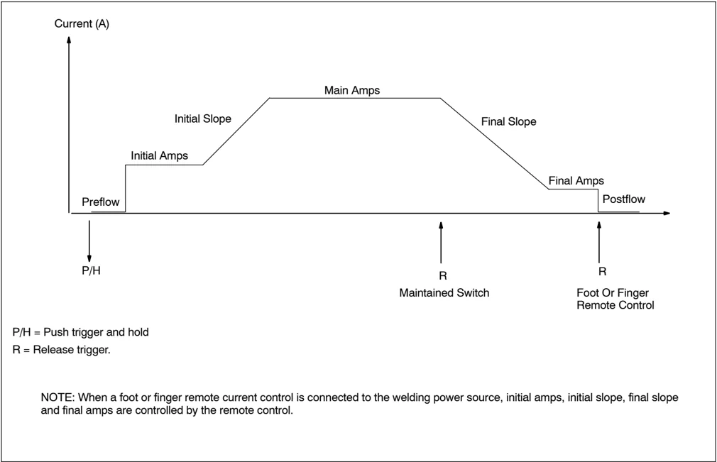
P/H = Push trigger and hold R = Release trigger.
NOTE: When a foot or finger remote current control is connected to the welding power source, initial amps, initial slope, final slope and final amps are controlled by the remote control.
B. Remote 2T Torch Trigger Operation
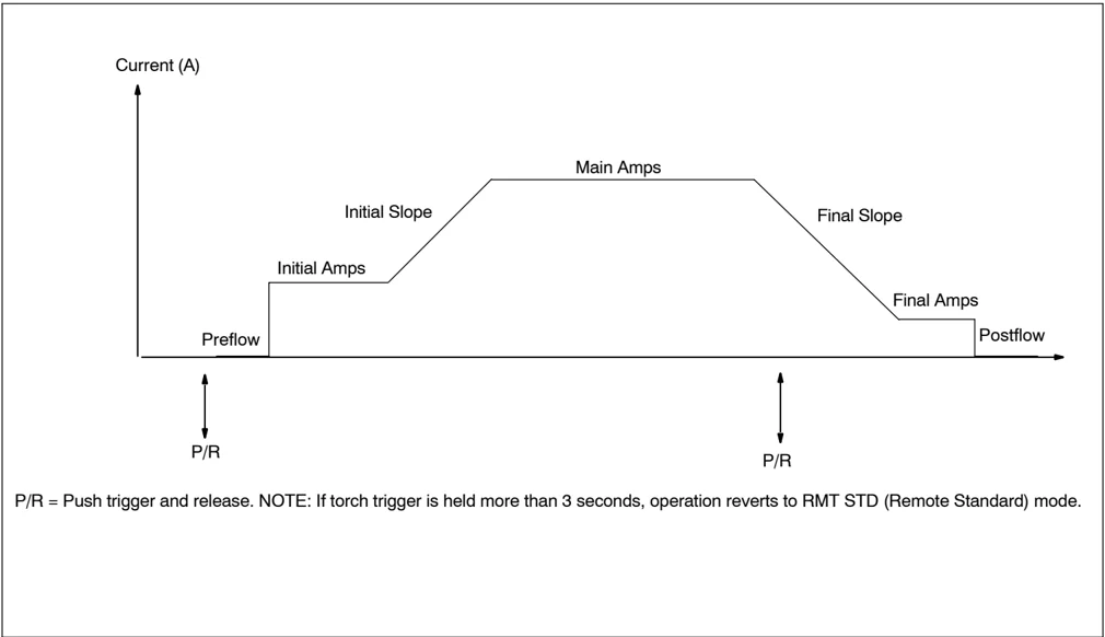
P/R = Push trigger and release. NOTE: If torch trigger is held more than 3 seconds, operation reverts to RMT STD (Remote Standard) mode.
C. Reconfiguring RMT 2T HOLD For 2T, 3T, Spot, 4T, 4T Momentary, Or Mini Logic Control
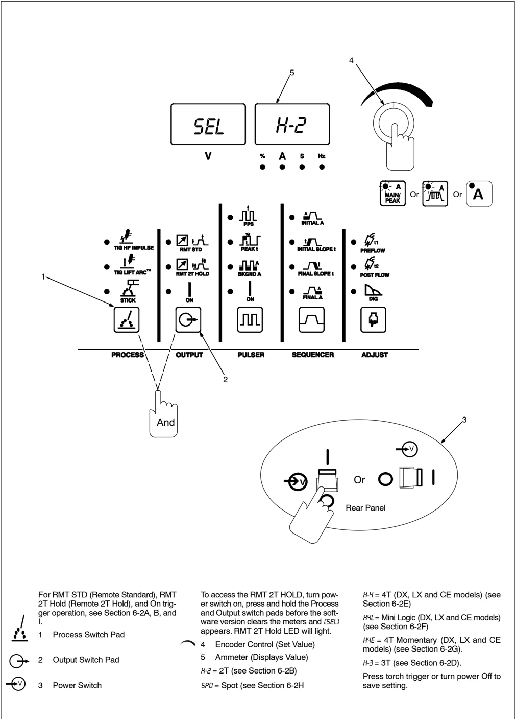
For RMT STD (Remote Standard), RMT 2T Hold (Remote 2T Hold), and On trigger operation, see Section 6-2A, B, and I.
1 Process Switch Pad 2 Output Switch Pad 3 Power Switch
To access the RMT 2T HOLD, turn power switch on, press and hold the Process and Output switch pads before the software version clears the meters and {SEL} appears. RMT 2T Hold LED will light.
4 Encoder Control (Set Value) 5 Ammeter (Displays Value) H-2 = 2T (see Section 6-2B) SP0 = Spot (see Section 6-2H)
H-4 = 4T (DX, LX and CE models) (see Section 6-2E) H4L = Mini Logic (DX, LX and CE models) (see Section 6-2F) H4E = 4T Momentary (DX, LX and CE models) (see Section 6-2G). H-3 = 3T (see Section 6-2D). Press torch trigger or turn power Off to save setting.
D. 3T Specific Trigger Method
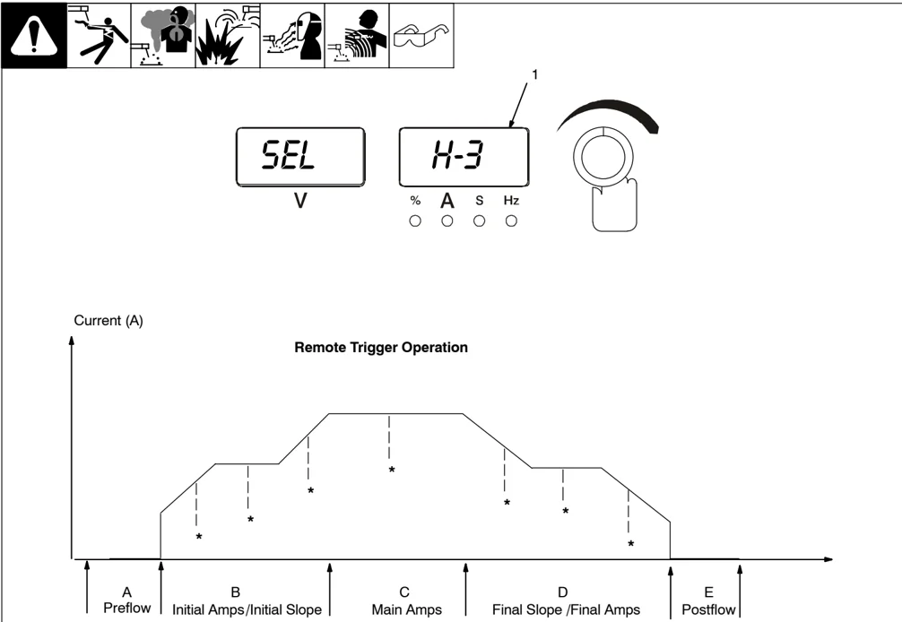
- Arc can be extinguished at any time by pressing and releasing both initial and final switches, or by lifting the torch and breaking the arc.
1 3T (Specific Trigger Operation) Sequencer is required to reconfigure for 3T. 3T requires a specific type of remote control with two independent momentary-contact switches. One will be designated initial switch, and it must be connected between Remote 14 receptacle pins A and B. The second will be designated as the final switch, and it must be connected between Remote 14 receptacle pins D and E. Select 3T according to Section 6-2C.
Definitions: Initial slope rate is the rate of amperage change determined by the initial amperage, initial slope time, and main amperage. Final slope rate is the rate of amperage change determined by the main amperage, final slope time, and final amperage.
Operation: A.. Press and release initial switch within 3/4 second to start shielding gas flow. To stop the preflow sequence before preflow time elapses (25 seconds), press and release final switch. The preflow timer will reset and the weld sequence can be started again.
If an initial switch closure is not made again before preflow time ends, gas flow stops, the timer resets, and an initial switch press and release is necessary to start the weld sequence again.
B.. Press initial switch to start arc at initial amps. Holding switch will change amperage at initial slope rate (release switch to weld at desired amperage level).
C.. When main amperage level is reached, initial switch can be released.
D.. Press and hold the final switch to decrease amperage at final slope rate (release switch to weld at desired amperage level).
E.. When final amperage has been reached, the arc extinguishes and shielding gas flows for the time set on the Postflow control.
Application: With the use of two remote switches instead of potentiometers, 3T gives the operator the ability to infinitely increase, decrease, or pause and hold amperage within the range determined by the initial, main, and final amperages.
E. 4T Specific Trigger Method (DX, LX And All CE Models)
1 4T (Specific Trigger Operation) Select 4T according to Section 6-2C. Torch trigger operation is as shown. 4T allows the operator to toggle between weld current and final current. NOTE: When a remote switch is connected to the welding power source, use the remote switch to control the weld cycle. Amperage is controlled by the welding power source. Application: Use 4T trigger method when the functions of a remote current control are desired, but only a remote on/off control is available.
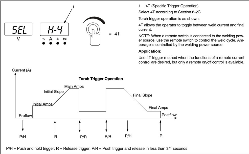
P/H = Push and hold trigger; R = Release trigger; P/R = Push trigger and release in less than 3/4 seconds
F. Mini Logic Operation (DX, LX And All CE Models)
1 Mini Logic Meter Display Select Mini Logic according to Section 6-2C. Torch trigger operation is as shown. Mini logic allows the operator to toggle between initial slope or main amps and initial amps. Final Amperage is not available. Final slope will always slope to minimum amperage and end the cycle. NOTE: When a remote switch is connected to the welding power source, use the remote switch to control the weld cycle. Amperage is controlled by the welding power source. Application: This ability to change current levels without either initial slope or final slope, gives the operator the opportunity to adjust filler metal without breaking the arc.
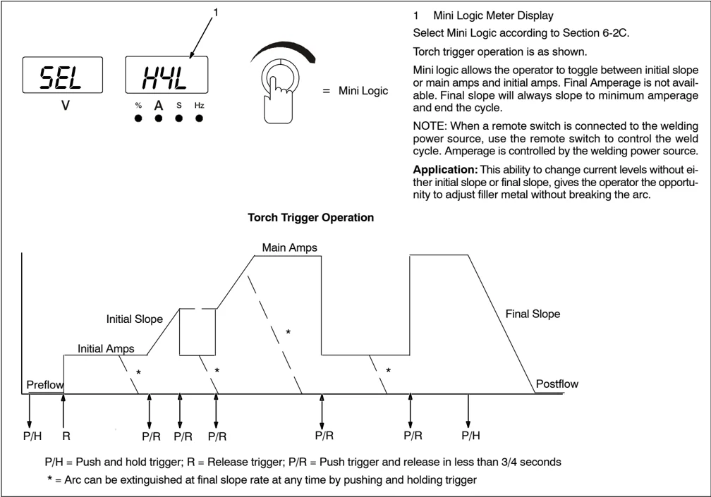
P/H = Push and hold trigger; R = Release trigger; P/R = Push trigger and release in less than 3/4 seconds
- = Arc can be extinguished at final slope rate at any time by pushing and holding trigger
G. 4T Momentary Operation (DX, LX And All CE Models)
1 4T Momentary Meter Display Select 4T Momentary according to Section 6-2C. 4T Momentary torch trigger operation is as shown. NOTE: When a remote switch is connected to the welding power source, use the remote switch to control the weld cycle. Amperage is controlled by the welding power source. Application: Use 4T Momentary trigger method when the functions of a remote current control are desired, but only a remote on/off control is available.
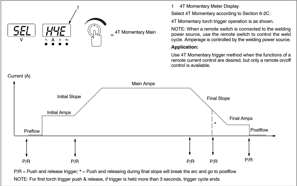
P/R = Push and release trigger; * = Push and releasing during final slope will break the arc and go to postflow NOTE: For first torch trigger push & release, if trigger is held more than 3 seconds, trigger cycle ends
H. Spot Control Operation (All Models)
1 Spot Function Meter Display Select Spot function according to Section 6-2C. NOTE: While in Spot Control, Sequencer settings are not be programmable. NOTE: When a remote switch is connected to the welding power source, use the remote switch to control the weld cycle. Amperage is controlled by the welding power source. Torch trigger operation is as shown. Application: Used for tacking and thin sheet joining.
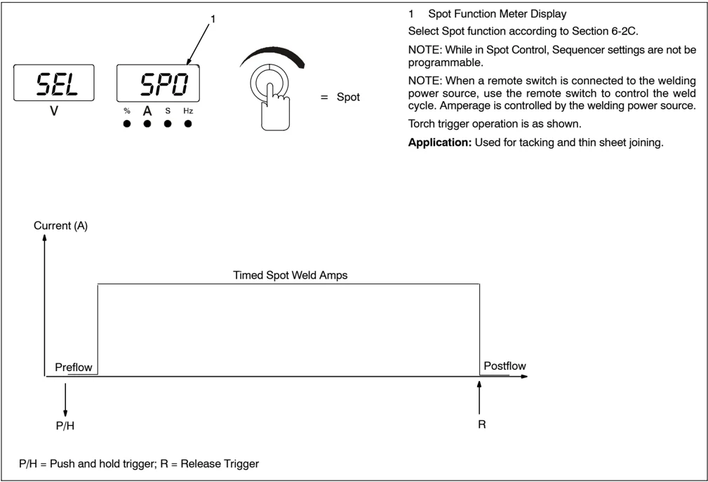
P/H = Push and hold trigger; R = Release Trigger
I. On Trigger Operation
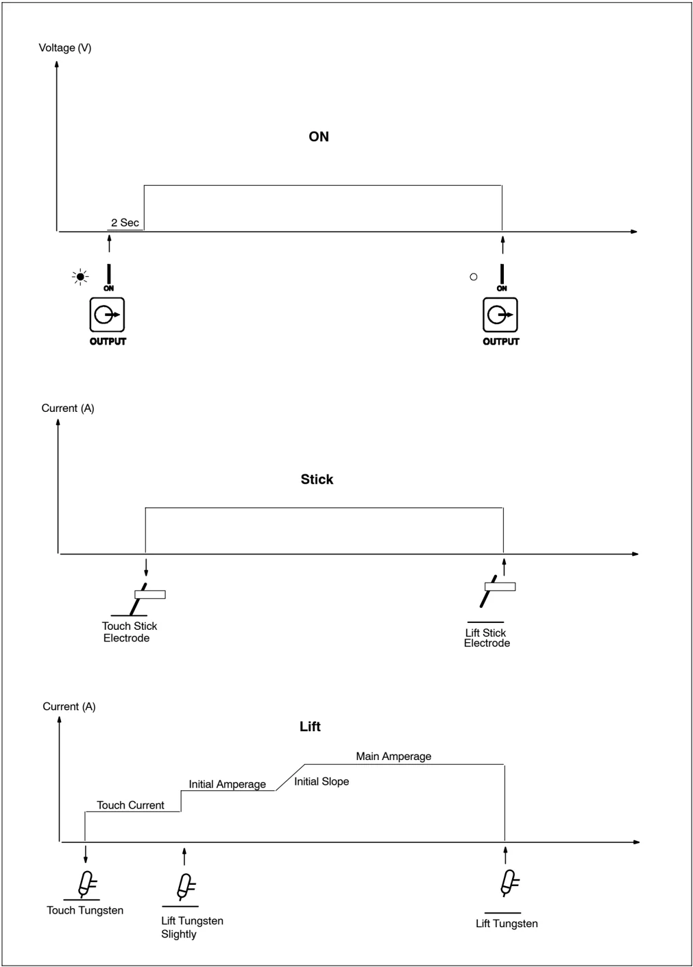
6-3. Arc Timer/Counter Display (All Models)
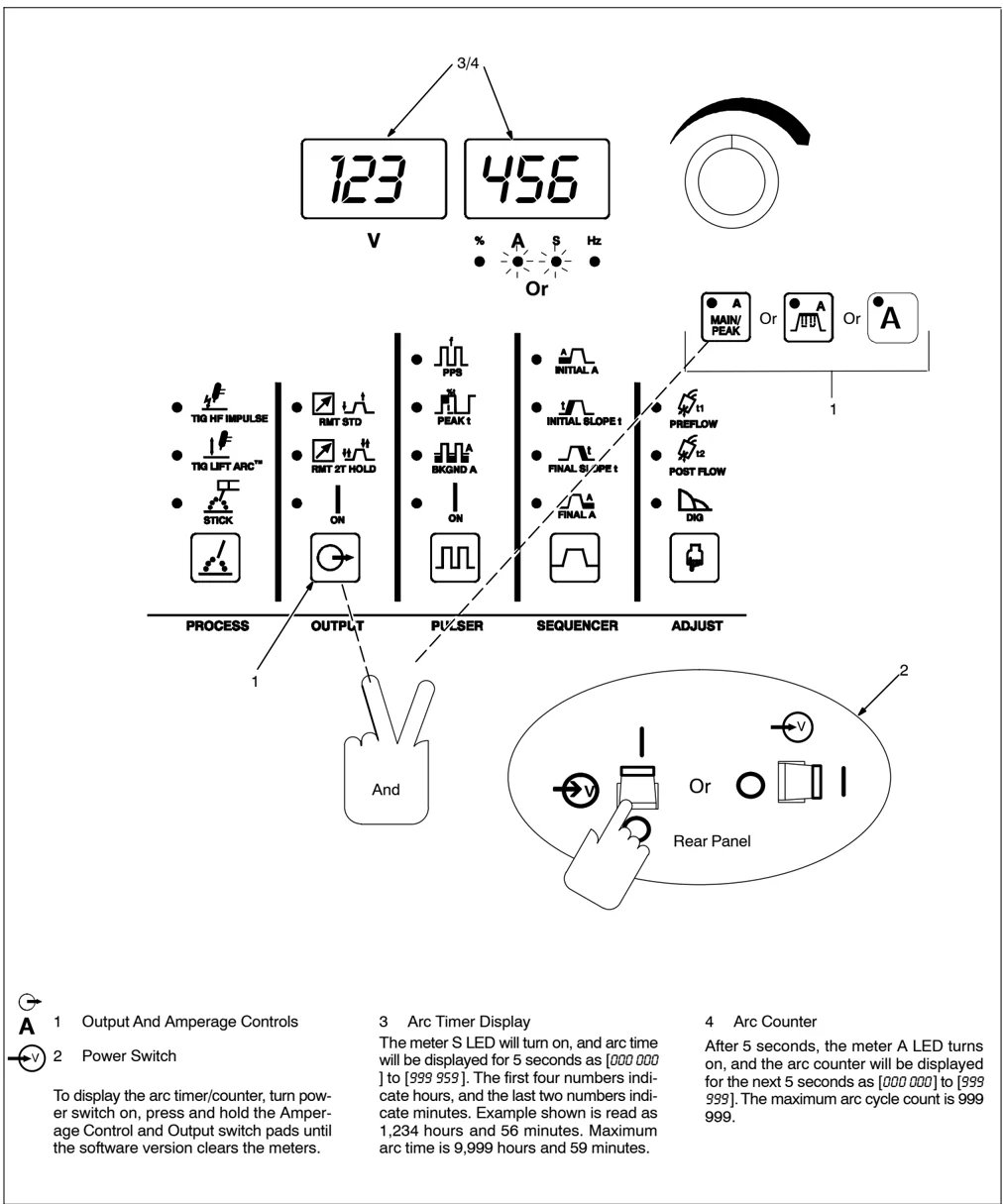
1 Output And Amperage Controls 2 Power Switch
To display the arc timer/counter, turn power switch on, press and hold the Amperage Control and Output switch pads until the software version clears the meters.
3 Arc Timer Display The meter S LED will turn on, and arc time will be displayed for 5 seconds as [000 000] to [999 999]. The first four numbers indicate hours, and the last two numbers indicate minutes. Example shown is read as 1,234 hours and 56 minutes. Maximum arc time is 9,999 hours and 59 minutes.
4 Arc Counter After 5 seconds, the meter A LED turns on, and the arc counter will be displayed for the next 5 seconds as [000 000] to [999 999]. The maximum arc cycle count is 999 999.
6-4. Lockout Functions
A. Accessing Lockout Capability
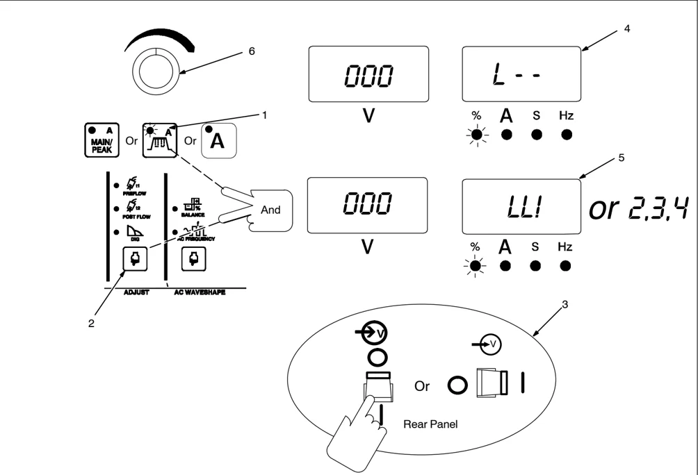
See Section 5-1 for explanation of controls referred to in all of Section 6-4.
There are four (1–4) lockout levels. Each successive level allows the operator more flexibility.
NOTE: Before activating lockout levels, be sure that all procedures and parameters are established. Parameter adjustment is limited while lockout levels are active.
1 Amperage (A) Switch Pad 2 Adjust Switch Pad 3 Power Switch 4 Lockout Off 5 Lockout On
To access lockout screens, turn power switch On. Press and hold the Amperage and Adjust switch pads until software version number clears the meters and Lockout Off or Lockout On appears. A Main/ Peak and % or S LED's will light.
6 Encoder Control
To turn On the lockout feature: Press Amperage (A) until % LED is on. Turn Encoder to select a three digit lockout code. The code will appear on the voltage meter. Select any number from [000] thru [999]. IMPORTANT: Document this code, it will be needed to turn lockout off. To select a lockout level, press Amperage (A) switch pad until meter S LED is lit. Turn Encoder to select a lockout level (see Sections B for lockout level descriptions). Once the desired three digits have been entered and a lockout level selected, press torch trigger or turn Off power to complete lockout on sequence. NOTE: Setting a three digit lockout number of [000], or setting a lockout level of [L--] will disable lockout.
To turn Off the lockout feature: Use Encoder control to enter the same three digits that were used to turn on the lockout feature. Press the Amperage (A) switch pad. The meter % LED will turn off and the S LED will light. The amperage meter will display [L--]. Lockout is now off. Press torch trigger or turn Off power to complete lock out Off sequence.
B. LockOut Levels
 Use Output Switch Pad To
Select A Trigger Method
For The TIG Process
 Use Output Switch Pad To
Select A Trigger Method
For The Stick Process
 Select Process
Process Selection
NOTE: Before activating lock out levels, be sure that all procedures and parameters are established.
Level 1
NOTE: Remote amperage control is not available in level 1.
TIG Output Selection
If either TIG HF Impulse or TIG Lift Arc process (see Section 5-9) is active when lockout level 1 is activated, the operator can choose RMT STD (Remote Standard) or RMT 2T HOLD (Remote 2T Hold). The On function is available if TIG Lift Arc is active.
If RMT 2T HOLD was reconfigured (see Section 6-2C) prior to lockout level 1 activation, the reconfigured output mode (4T, 4T momentary, mini logic, or spot) is available instead of RMT 2T.
Stick Output Selection
If the Stick process is active when lockout level 1 is activated, choose between RMT STD or On.
When parameter choice or selection is limited by lock level 1, [L-1] is displayed.
Level 2
NOTE: Remote amperage control is not available in level 2.
Includes all the functions of level 1 plus Polarity and Process Selection (see Sections 5-6 and 5-7).
When parameter change or selection is limited by lock level 2, [L-2] is displayed.
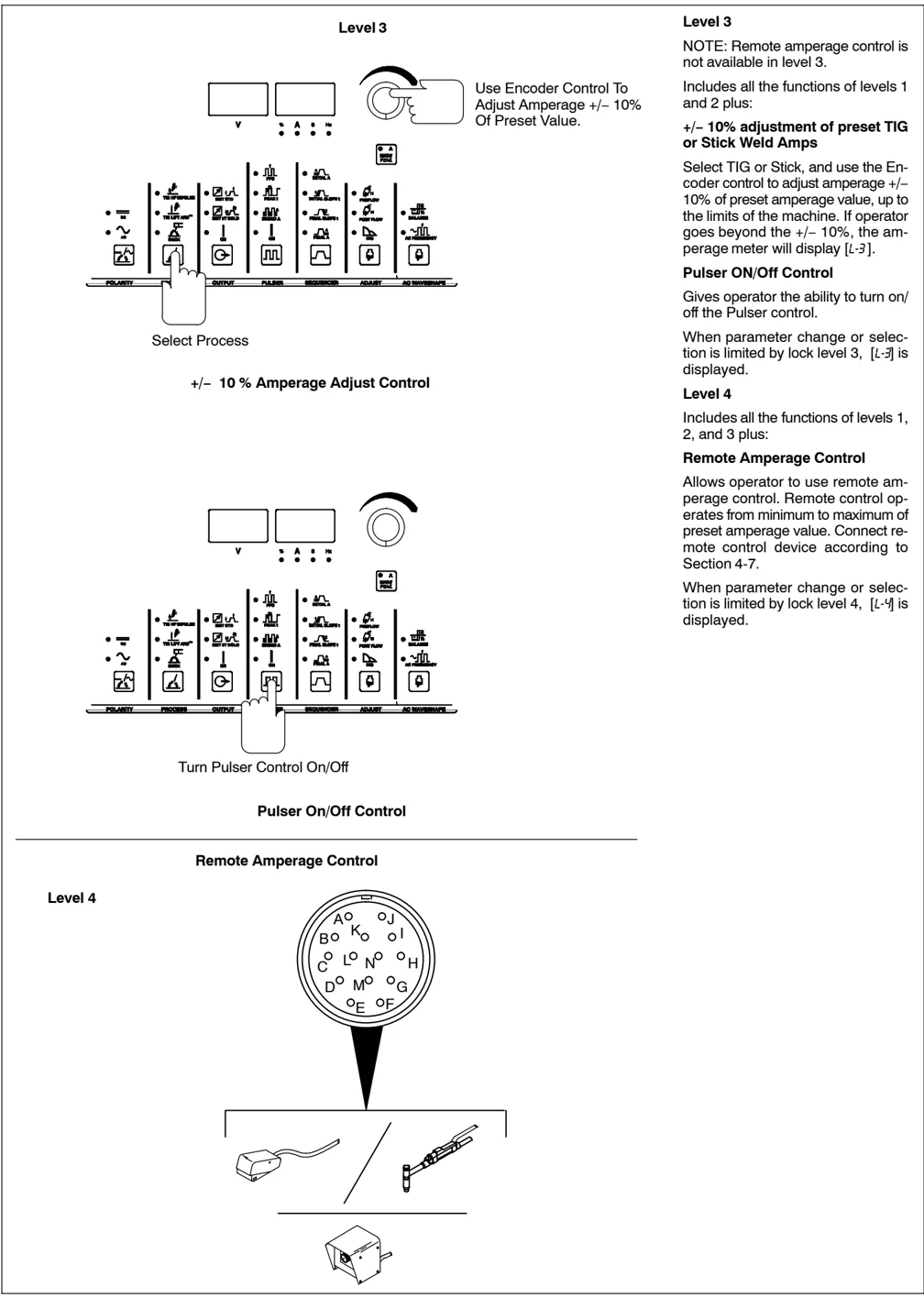
B. Lock Out Levels (Continued)
Select Process
+/- 10 % Amperage Adjust Control
Turn Pulser Control On/Off
Pulser On/Off Control
Remote Amperage Control
Level 4
Level 3 NOTE: Remote amperage control is not available in level 3.
Includes all the functions of levels 1 and 2 plus:
+/- 10% adjustment of preset TIG or Stick Weld Amps Select TIG or Stick, and use the Encoder control to adjust amperage +/- 10% of preset amperage value, up to the limits of the machine. If operator goes beyond the +/- 10%, the amperage meter will display [L-3].
Pulser ON/Off Control Gives operator the ability to turn on/ off the Pulser control.
When parameter change or selection is limited by lock level 3, [L-3] is displayed.
Level 4 Includes all the functions of levels 1, 2, and 3 plus:
Remote Amperage Control Allows operator to use remote amperage control. Remote control operates from minimum to maximum of preset amperage value. Connect remote control device according to Section 4-7.
When parameter change or selection is limited by lock level 4, [L-4] is displayed.
6-5. Setting Unit To Display PPP While Pulse Welding (DX And LX Models Only)
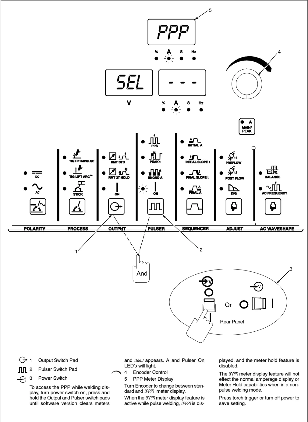
1 Output Switch Pad 2 Pulser Switch Pad 3 Power Switch
To access the PPP while welding display, turn power switch on, press and hold the Output and Pulser switch pads until software version clears meters and {SEL} appears. A and Pulser On LED's will light.
4 Encoder Control 5 PPP Meter Display
Turn Encoder to change between standard and {PPP} meter display.
When the {PPP} meter display feature is active while pulse welding, {PPP} is displayed, and the meter hold feature is disabled.
The {PPP} meter display feature will not effect the normal amperage display or Meter Hold capabilities when in a non-pulse welding mode.
Press torch trigger or turn off power to save setting.
6-6. Stick Open-Circuit Voltage (OCV) Selection (All Models)
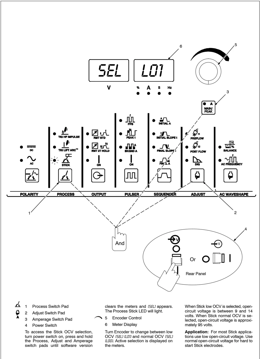
1 Process Switch Pad 2 Adjust Switch Pad 3 Amperage Switch Pad 4 Power Switch
To access the Stick OCV selection, turn power switch on, press and hold the Process, Adjust and Amperage switch pads until software version clears the meters and {SEL} appears. The Process Stick LED will light.
5 Encoder Control 6 Meter Display
Turn Encoder to change between low OCV {SEL} {L01} and normal OCV {SEL} {L001}. Active selection is displayed on the meters.
When Stick low OCV is selected, open-circuit voltage is between 9 and 14 volts. When Stick normal OCV is selected, open-circuit voltage is approximately 95 volts.
Application: For most Stick applications use low open-circuit voltage. Use normal open-circuit voltage for hard to start Stick electrodes.
SECTION 7 – MAINTENANCE AND TROUBLESHOOTING
7-1. Routine Maintenance
Disconnect power before maintaining.
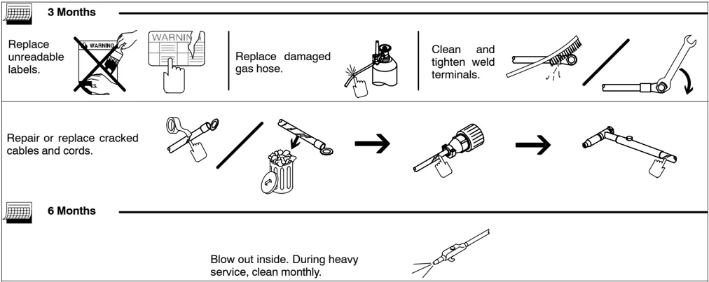
3 Months
Replace unreadable labels.
Replace damaged gas hose.
Clean and tighten weld terminals.
Repair or replace cracked cables and cords.
6 Months
Blow out inside. During heavy service, clean monthly.
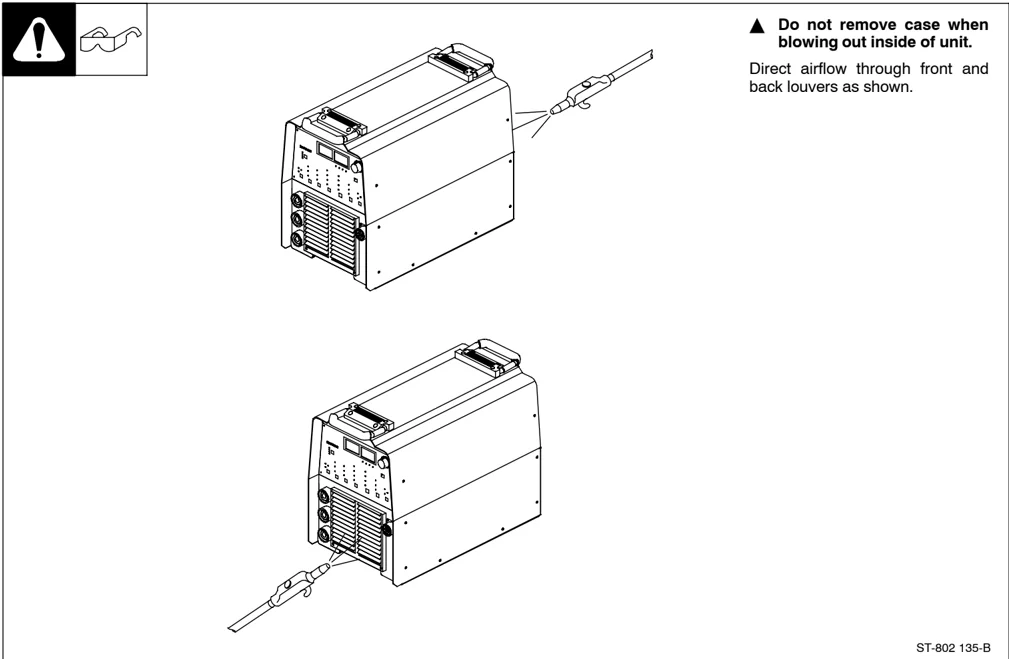
7-2. Blowing Out Inside of Unit
Do not remove case when blowing out inside of unit. Direct airflow through front and back louvers as shown.
ST-802 135-B
7-3. Voltmeter/Ammeter Help Displays
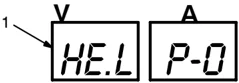
All directions are in reference to the front of the unit. All circuitry referred to is located inside the unit.
1 Typical Help Display (For Help 0)
-
Help 0 Display
Indicates a short in the thermal protection circuitry located on the left side of the unit. Contact a Factory Authorized Service Agent if this display is shown. -
Help 1 Display
Indicates a malfunction in the primary power circuit caused by an overcurrent condition in the primary IGBT switching circuit. Contact a Factory Authorized Service Agent if this display is shown. -
Help 2 Display
Indicates an open in the thermal protection circuitry located on the left side of the unit. Contact a Factory Authorized Service Agent if this display is shown. -
Help 3 Display
Indicates the left side of the unit has overheated. The unit has shut down to allow the fan to cool it (see Section 4-3). Operation will continue when the unit has cooled. -
Help 4 Display
Indicates an open in the thermal protection circuitry located on the right side of the unit. Contact a Factory Authorized Service Agent if this display is shown. -
Help 5 Display
Indicates the right side of the unit has overheated. The unit has shut down to allow the fan to cool it (see Section 4-3). Operation will continue when the unit has cooled. -
Help 6 Display
Indicates that the input voltage is too low and the unit has automatically shut down. Operation will continue when the voltage is within the operating range (±10%). Have an electrician check the input voltage if this display is shown. -
Help 7 Display
Indicates that the input voltage is too high and the unit has automatically shut down. Operation will continue when the voltage is within the operating range (±10%). Have an electrician check the input voltage if this display is shown. -
Help 8 Display
Indicates a malfunction in the secondary power circuit of the unit. There is a high open circuit condition. Contact a Factory Authorized Service Agent if this display is shown. -
Help 9 Display
Indicates a short in the thermal protection circuitry located on the right side of the unit. Contact a Factory Authorized Service Agent if this display is shown. -
Help 10 Display
Indicates torch trigger is depressed. Release trigger to continue. -
Help 12 Display
Indicates a non-allowable set-up on the front panel. -
Help 13 Display (LX Models Only)
Output disable open causing weld output to stop, but gas continues to flow. -
Help 21 Display
Indicates voltage or current feedback has been detected with contactor off. Contact a Factory Authorized Service Agent if this display is shown. -
Help 22 Display
Voltage and current not present with contactor on. Contact a Factory Authorized Service Agent if this display is shown.
7-4. Troubleshooting

| Trouble | Remedy |
|---|---|
| No weld output; unit completely inoperative. | Place line disconnect switch in On position (see Section 4-12). |
| Check and replace line fuse(s), if necessary, or reset circuit breaker (see Section 4-12). | |
| Check for proper input power connections (see Section 4-12). | |
| No weld output; meter display On. | If using remote control, be sure correct process is enabled to provide output control at Remote 14 receptacle (see Sections 5-1 and 4-7). |
| Input voltage outside acceptable range of variation (see Section 4-11). | |
| Check, repair, or replace remote control. | |
| Unit overheated. Allow unit to cool with fan On (see Section 4-3). | |
| Erratic or improper weld output. | Use proper size and type of weld cable (see Section 4-6). |
| Clean and tighten all weld connections. | |
| No 115 volts ac output at duplex receptacle. | Reset supplementary protector CB1 (see Section 4-5). |
| Fan not operating. | Check for and remove anything blocking fan movement. |
| Have Factory Authorized Service Agent check fan motor. |
| Trouble | Remedy |
|---|---|
| Wandering arc | Use proper size tungsten. |
| Use properly prepared tungsten. | |
| Reduce gas flow rate. | |
| Tungsten electrode oxidizing and not remaining bright after conclusion of weld. | Increase postflow time. |
| Check and tighten all gas fittings. | |
| Water in torch. Refer to torch manual. |