Wow, this is from something from a number of years ago. I DID rewire the coils, and we got pretty good signals going into the converter, but the output was no good. I don't know if we didn't wire it right, or if the ferrite was damaged. Anyway, as far as I know, the scale never worked again. Possibly somebody found a read head surplus and got it working again.
Jon
Didn't find your answer? Ask the community — no account required.
C
CARLOS REIS
replying to Jon Elson, CARLOS REIS wrote: Thanks Jon
I will try to rewire one of this days
N
Ned Simmons
I was the original poster of that thread. And in my case the problem also turned out to be the read head. I was unable to find a complete used scale of the proper length, but was able to swap out the head from another scale. Two things to be aware of when doing this: First, the scale is calibrated by tensioning the scale rod in the housing, and you need to remove the rod to swap read heads. I was able to re-calibrate to my satisfaction with gage blocks and a 50 millionths test indicator. Second, what appear to be rivets in the housing covers are actually fillister head machine screws with no slot or other tool recess. A small drill chuck will grab them and they unscrew easily.
J
Joe Gwinn
The heads are probably slightly oval - I've seen ads from a company that makes such screws and the matching drivers.
Joe Gwinn
N
Ned Simmons
Could be, the heads look perfectly round to the naked eye, but measure about .010 out of round.
J
Jon Elson
OK, if I had a complete choice, I'd do this under a stereo zoom microscope, and use fine tweezers. I do micro soldering all the time anyway, but this was something that really tested my skills.
Jon
J
Jim Wilkins
Conductive epoxy is good for really fine work. I repaired a broken 1 mil x 5 mil bonding ribbon on a laser diode die with it.
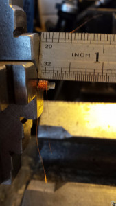
replying to Jon Elson, CARLOS REIS wrote: Working on it right now!
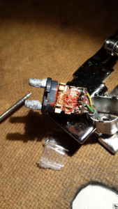
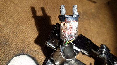
Some pictures to sow the complete mess...
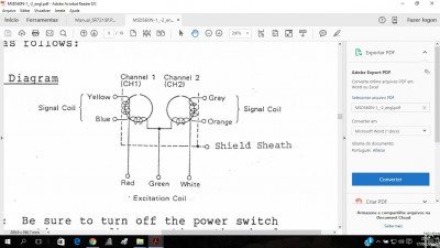
I'm working by fun and trial error because: I don't know the wire sense of rotation I don't know what is the channel one or channel two coil I've simplified the excitation coil because till now I was unable to do it similar to the original one
I've also done lots of ridiculously small soldering with the aid of a stereo zoo scope, but I've never used conductive epoxy.
Properly cleaned and fluxed, solder will (usually) go where it's supposed to go and (usually) stay out of where it's not supposed to go. How do you handle this with epoxy? If you accidentally get some where it's not supposed to go, can you clean it off?
I could certainly see using conductive epoxy for repairing Kapton flat cables. That stuff is really hard to solder without melting lots of plastic.
E
Ed Huntress
Speaking of conductive plastics, you guys may be interested in a big push that HP is making into 3D printing (additive manufacturing). They're embedding conductive-plastic electrical conductors in the 3D parts. I don't know the market they're shooting for, but my guess is that it's automotive.
J
Jim Wilkins
I used conductive epoxy only where I had to. Gold bonding ribbon dissolves instantly in solder. I soldered temporary isolating cuts in not-much-larger 6 mil copper traces. It's easier if the cut is skewed so the beveled ends overlap.
The bonding ribbons were fairly long arches from copper pads to the laser diode die which was mounted on a diamond substrate. Apparently the tech at the first government lab that had the project was incapable of such delicate work, so Mitre got it and I patched his mistakes. They knew I could stack up 3D assemblies of 0201 resistor chips. My demo was to join 0.015" solder into linked rings.
--jsw
J
Jon Elson
OHHH, MY! That looks like a total mess. Did you rewind the coils? The one I worked on, the coils were OK, just the connection to the terminal strip were broken.
Good luck, you are going to need it!
Jon
M
mogulah
ereo zoo scope, but I've never used conductive epoxy.
d to go and (usually) stay out of where it's not supposed to go. How do you handle this with epoxy? If you accidentally get some where it's not suppos ed to go, can you clean it off?
ables. That stuff is really hard to solder without melting lots of plastic.
Yeah, at the very least, until 2004 or 2005, I hadn't known that magnetic f ields go through non-shielded insulation until I saw another installer on a construction site using a "cable verifier". I think it was made by Fluke. You hold it up to a low voltage wire and the cable verifier's speaker will play the communications out loud that it picks up in the wire (via magnetic field).
E
Ed Huntress
Keep in mind that this is not anything going on through insulation. The conductive plastic conducts current directly. I can be multiple "wires" embedded in a 3D-printed part or device.
C
CARLOS REIS
replying to Jon Elson, CARLOS REIS wrote: Bad news I gave up. Couldn't have any readings after trying for a while.
Thanks everyone for help and support
Join the Discussion
Have something to add? Share your thoughts — no account required.
Didn't find your answer?
Ask the community — no account required
Report Content
You are reporting this content to the moderators. They will look at it
ASAP.