8UAPS / 8UAFS
8 CHANNEL RADIO CONTROL SYSTEM
I NSTRUCTION M ANUAL

INTRODUCTION
Thank you for purchasing a Futaba® 8Usuper series digital proportional R/C system. This system is extremely versatile and may be used by beginners and pros alike. In order for you to make the best use of your system and to fly safely, please read this manual carefully. If you have any difficulties while using your system, please consult the manual, your hobby dealer, or Futaba.
Owner's Manual
This manual is not just a translation and has been carefully written to be as helpful to you, the new owner, as possible. There are many pages of setup procedures, examples, and trimming instructions. If you feel that any corrections or clarifications should be made, please jot them down on a piece of paper and send them to the factory. Due to unforeseen changes in production procedures, the information contained in this manual is subject to change without notice.
Application, Export, and Reconstruction
-
This product may be used for model airplane or surface use if on the correct frequency. The product described in this manual is subject to regulations of the Ministry of Radio/Telecommunications and is restricted under Japanese law to such purposes.
-
Exportation precautions (a) When this product is exported from Japan, its use is to be approved by the Radio Law of the country of destination. (b) Use of this product with other than models may be restricted by Export and Trade Control Regulations. An application for export approval must be submitted.
-
Modification, adjustment, and replacement of parts
Futaba is not responsible for unauthorized modification, adjustment, and replacement of parts of this product.
The Following Statement Applies to the Receiver (for U.S.A.)
This device complies with part 15 of the FCC rules. Operation is subject to the following two conditions: (1) This device may not cause harmful interference, and (2) This device must accept any interference received, including interference that may cause undesired operation.
The RBRC™ Seal (for U.S.A.)
The RBRC™ SEAL on the (easily removable) nickel-cadmium battery contained in Futaba products indicates that Futaba Corporation of America is voluntarily participating in an industry program to collect and recycle these batteries at the end of their useful lives, when taken out of service within the United States. The RBRC™ program provides a convenient alternative to placing used nickel-cadmium batteries into the trash or municipal waste which is illegal in some areas.
Futaba Corporation of America's payments to RBRC™ makes it easy for you to return the spent battery to Futaba for recycling purposes. You may also contact your local recycling center for information on where to return the spent battery. Please call 1-800-8-BATTERY for information on Ni-Cd battery recycling in your area. Futaba Corporation of America's involvement in this program is part of its commitment to protecting our environment and conserving natural resources.
 NOTE: Our instruction manuals need to encourage our customers to return spent batteries to Futaba or a local recycling center in order to keep a healthy environment.
RBRC™ is a trademark of the Rechargeable Battery Recycling Corporation.
Meaning of Special Markings
Pay special attention to the safety at the parts of this manual that are indicated by the following marks.
⚠ DANGER Procedures which may lead to a dangerous condition and cause death or serious injury to the user if not carried out properly.
⚠ WARNING Procedures which may lead to a dangerous condition or cause death or serious injury to the user if not carried out properly, or procedures where the probability of superficial injury or physical damage is high.
⚠ CAUTION Procedures where the possibility of serious injury to the user is small, but there is a danger of injury, or physical damage, if not carried out properly.
Symbol: ⊘ ; Prohibited ! ; Mandatory
Flying Safety
⚠WARNING To ensure the safety of yourself and others, please observe the following precautions:
Ni-cd Battery ❗ Charge the Batteries! Don't forget to recharge the batteries before each flying session. Plug in the charger that comes in this system and hook up the transmitter and airborne batteries the day before a planned flying session. A low battery will soon die causing loss of control and a crash. When you begin your flying session, reset your 8Usuper's built-in timer, and during the session pay attention to the duration of usage. ❗ Quit flying long before your batteries become low on charge. On-field charging of your batteries with a field charger is not recommended. Overcharging the Ni-Cd batteries with a fast-charger may cause overheating and a premature failure.
Flying field We recommend that you fly at a recognized model airplane flying field. You can find model clubs and fields by asking your nearest hobby dealer, or contacting the Academy of Model Aeronautics. ❗ Always pay particular attention to the flying field's rules, as well as the presence and location of spectators, the wind direction, and any obstacles on the field. Be very careful flying in areas near power lines, tall buildings, or communication facilities as there may be radio interference in their vicinity. If you must fly away from a club field, be sure there are no other modelers flying within a two-mile range, or you may lose control of your aircraft.
On the flying field ❗ Before flying, be sure that the frequency you intend to fly with is not in use, and secure any frequency control device (pin, tag, etc.) for that frequency before turning on your transmitter. Never believe that it's possible to fly two or more models on the same frequency at the same time. Even though there are different types of modulation (AM, FM, PCM), only one model may be flown on a single frequency.
To prevent possible damage to your radio gear, turn the power switches on and off in the proper sequence, given below. ❗ When you are ready to fly your model, move the throttle stick to the low speed position, or do whatever is necessary to command your motor NOT to run. Then, you may turn on the transmitter power followed by the receiver power. When you have finished flying, begin by turning off the receiver power, then turn off the transmitter power. If you do not follow these procedures, you may damage your servos or control surfaces, flood your motor, or in the case of electric-powered models, the motor may unexpectedly turn on and cause a severe injury.
We recommend that you range-check your system before each flying session. ❗ Before starting the engine, fully extend the transmitter antenna, power up the transmitter and receiver, and check to be sure that the servos follow the
1
movement of the sticks. If a servo operates abnormally, don’t attempt to fly until you determine the cause of the problem.
❗ Finally, before starting the engine, be sure to check that the transmitter model memory is correct for the chosen model, and (for PCM receivers only) that the fail safe system functions properly when the transmitter is shut off.
❗ While you’re getting ready to fly, if you place your transmitter on the ground, be sure that the wind won’t tip it over. If it is knocked over, the throttle stick may be accidentally moved causing the engine to race.
❗ Before taxiing, be sure to extend the transmitter antenna to its full length. A collapsed antenna will reduce your flying range and cause a loss of control. It is a good idea to avoid pointing the transmitter antenna directly at the model, since the signal is weakest in that direction.
🚫 Don’t fly in the rain! Water or moisture may enter the transmitter through the antenna or stick openings and cause erratic operation or loss of control. If you must fly in wet weather during a contest, be sure to cover your transmitter with a plastic bag or waterproof barrier.
3
TABLE OF CONTENTS
-
Safety Precautions (DO NOT operate without reading) ........ 1
-
Introduction to the 8UA System ........ 6
-
Contents & Technical Specifications ........ 7
-
Optional Accessories ........ 7
-
Transmitter Controls and Switch Identification ........ 8
-
Transmitter Switch Assignments ........ 9
-
Charging the Ni-Cd Battery ........ 10
-
Adjusting Length of Non-slip Control Sticks ........ 10
-
Stick Spring Tension Adjustment ........ 11
-
Changing Transmitter Mode ........ 11
-
Receiver and Servo Connections ........ 12
-
Radio Installation Precautions ........ 13
-
Airplane Frequencies ........ 14
-
Transmitter Displays and Programming Keys ........ 15
-
Warning and Error Displays ........ 16
-
AIRCRAFT FUNCTIONS INDEX ........ 19
-
Basic Aircraft Functions Diagram ........ 20
-
Aircraft Advance Menu Functions Diagram ........ 21
-
Aircraft Setup Example (F3A model) ........ 22-23
-
Pattern Aircraft Trimming Chart ........ 24-25
-
Aircraft (ACRO) & Sailplane (GLID1FLP & GLID2FLP) Basic Menu Functions ........ 26-40
-
ATV ........ Adjustable Travel Volume ........ 26
-
D/R ........ Dual Rates ........ 26
-
EXP ........ Exponential throw ........ 28
-
IDL-DN ........ Idle Down ........ 29
-
F/S ........ Fail Safe ........ 29
-
REVERS ........ Servo Reverse ........ 30
-
PARA ........ Parameter ........ 31
-
DATASET ........ Data Reset ........ 31
-
ATL ........ ATL trim ........ 31
-
EG/S ........ Engine Starter ........ 32
-
TYPE ........ Model Type ........ 32
-
MOD ........ Modulation (FM/PPM or PCM) ........ 34
-
AIL2 ........ Second Aileron ........ 34
-
TRAINR ........ Trainer ........ 34
-
MODEL ........ Model ........ 36
-
SEL ........ Model Select ........ 36
-
COPY ........ Data Copy ........ 36
-
NAME ........ Model Name ........ 37
-
TRIM ........ Trim ........ 38
-
RSET ........ Trim Reset ........ 38
-
STEP ........ Trim Steps ........ 38
-
DISP ........ Trim reverse display ........ 39
-
SUBTRM ........ Subtrim ........ 39
-
TH-CUT ........ Throttle Cut ........ 40
-
TIMER ........ Timer ........ 40
-
Aircraft (ACRO) Advance Menu Functions ........ 42-51
-
PMIX-1-7 ........ Programmable Mixers (1-7) ........ 43-44
-
FLPRON ........ Flaperon (combined flaps & ailerons) ........ 45
-
FLAPTRM ........ Flap trim ........ 46
-
AI-DIF ........ Aileron Differential (more up than down) ........ 46
-
ABRAKE ........ Airbrake settings ........ 47
4
-
ELE→FL ........ Elevator→Flap mixing ........ 48
-
V-TAIL ........ V-tail mixing ........ 48
-
ELEVON ........ Elevon mixing (tailless models) ........ 49
-
ALVATR ........ Ailevator (differential elevator) ........ 49
-
SNP ........ Snap Roll ........ 50
-
TH-DLY ........ Throttle delay ........ 51
-
TH→NDL ........ Throttle needle ........ 51
-
SAILPLANE SECTION INDEX ........ 52
-
Sailplane (GLID1FLP & GLID2FLP) Functions Diagram ........ 53
-
Sailplane Setup Example (GLID 2FLP Competition model with 2 ailerons, 2 flaps) ........ 54-57
-
Sailplane Trimming Chart ........ 57-58
-
Sailplane Advance Menu Functions ........ 59
-
PMIX-1-7 ........ Programmable mixing ........ 43
-
SPEED ........ Speed presets ........ 63
-
START ........ Start (launch) presets ........ 62
-
V-TAIL ........ V-tail mixing ........ 48
-
ELE→FL ........ Elevator→Flap mixing ........ 48
-
AIL→FL ........ Aileron→flap mixing ........ 61
-
FLP→AI ........ Flap→Aileron mixing ........ 60
-
BFLY ........ Butterfly (“Crow”) mixing ........ 59
-
AI-DIF ........ Aileron differential ........ 46
-
FLPTRM ........ Camber travel (flap trim) ........ 46
-
AIL→RUD ........ Aileron→Rudder coupling (Use a PMIX) ........ 43
-
HELICOPTER SECTION INDEX ........ 64
-
Helicopter (HELISWH1/SWH2/SWH4/SR-3/SN-3) Functions Diagram ........ 65
-
Helicopter Setup Example ........ 66
-
Helicopter Trimming Chart ........ 69
-
Helicopter Basic Functions ........ 70
-
TH-CRV ........ Throttle curve (Normal) ........ 70
-
PI-CRV ........ Pitch curve (Normal) ........ 71
-
REVOLU ........ Revolution mixing (Normal) ........ 72
-
SWASH ........ Swash AFR ........ 73
-
INVERT ........ Inverted ........ 74
-
TH-CUT ........ Throttle Cut ........ 75
-
Helicopter Advance Menu Functions ........ 76
-
TH-CRV ........ Throttle Curve (Normal, Idle-up 1 & 2) ........ 77-78
-
TH-HLD ........ Throttle Hold ........ 79
-
OFST-1-2-iv ... Offset -1-2-iv ........ 80
-
DELAY ........ Delay ........ 80
-
PMIX-1-2 ........ Programmable Mixing ........ 81-82
-
HOV-TH ........ Hovering Throttle ........ 83
-
HOV-PI ........ Hovering Pitch ........ 83
-
GYRO ........ Gyro Mixing ........ 84
-
GOVrpm ........ Governor Mixing ........ 84
-
TH-NDL ........ Throttle Needle Mixing (Normal, Idle-up 1 & 2) ........ 86
-
INVERT CROSS.. Inverted Cross Position ........ 87
-
REVOLU ........ Revolution Mixing (Normal, Idle-up 1 & 2) ........ 87
-
PI-CRV ........ Pitch Curve (Normal, Idle-up 1 & 2, Hold) ........ 89-90
-
Handling the CAMPac ........ 91
-
Glossary ........ 92
-
Data Sheets: ACRO, GLID1FLP, GLID2FLP, HELISWH1 ........ 94-96
-
Factory Repair Service ........ 97
5
Introduction to the 8UA System
TRANSMITTER
The versatile FP-T8UAFS/T8UAPS PCM1024 multi-function 8-channel transmitter may be used with any Futaba PCM1024 receiver! In addition, your system will work with Futaba FM/PPM receivers when you select the FM transmission option. The large liquid-crystal display panel allows rapid data input into its easy-to-read LCD display. To allow efficient programming, all of the transmitter’s functions have been separated into Basic Menu and Advanced Menu functions.
The 8UA transmitter has electronic trims so that rapid yet precise trim adjustment is possible while flying. These exclusive trims are designed to that when the trim lever is activated, trim movement accelerates, and in addition, each trim’s sensitivity may be programmed to match the model or control. For convenience, the location of the trim is constantly displayed on the LCD panel.
The 8UA system comes complete with programming for ACRO (aircraft), HELISWH1/SWH2/SWH4/SR-3/SN-3 (helicopter), or GLID1FLP/2FLP (sailplane) mixing and can accommodate virtually any model configuration. The compact, ergonomically-designed transmitter holds completely independent memories for eight different models. [For modelers requiring additional storage, memory for another eight models can be added using the DP16K CAMPac (available separately). You may also easily transfer your model data to another T8UA/T8UH transmitter plugging your CAMPac into the other transmitter. The data pack does not require any battery backup and can be stored indefinitely.]
The 8UA features a new stick design which provides an improved feel. The sticks’ length and tension may be adjusted. Switches are provided for dual rate (D/R), programmable mixers (PMIX), and other functions, and the location of the switches can be changed electronically to suit your own preferences. For those learning to fly, the transmitter has “buddy-box” capability and the training channels can be selected by the instructor. [The trainer cord is sold separately.]
Standard programming features include servo reversing for all channels, ATV on all channels, dual rates, exponential, throttle cut, electronic subtrim on all channels, and fail safe on all channels (PCM transmission only). An alphabetic name may be used for each model stored in the eight model memories.
The 8UA features a number of special mixing features applicable to all types of flying models. For aircraft, there are extensive preprogrammed mixing features: aileron differential, flaperon, V-tail, elevon, airbrake (with delayed elevator), elevator→flap, snap roll in 4 directions, throttle→needle (with acceleration), idle-down, engine starting, and second aileron switching. Helicopter features include throttle and pitch curve settings, hovering pitch and throttle, revolution mixing, delay, offset, invert, throttle needle, gyro mixing, and governor mixing. Special sailplane features for single and dual flap servos include flap→aileron, aileron→flap, elevator→flap, aileron differential, butterfly mixing, camber control, and start (launch) and speed presets.
If you plan to fly sailplanes extensively, you may wish to buy the 8UH (helicopter) system, since its three-position switch is on the top left of the transmitter, while for the 8UA (aircraft) system, the three-position switch is on the top right.
R148 RECEIVER
The R148 eight-channel receiver included with your system is a high-sensitivity narrow-band, dual conversion receiver. Not much larger than a pack of gum, it weighs just 1.07 oz yet provides superior range and performance.
SERVOS
The S3001 servo includes a ball bearing and provides 60° of travel in a rapid 0.22 second, along with a rated torque of 41.7 oz-in. The S148 servo is a standard servo with similar torque rating and transit speed in a slightly lighter package.
6
CONTENTS AND TECHNICAL SPECIFICATIONS, AIRCRAFT VERSION (T8UAPS and T8UAFS Series)
Specifications and ratings are subject to change without notice.
Your 8UAPS (PCM) or 8UAFS (FM) system includes the following components:
- 8UA Transmitter, including RF module
- R148DP/DF Receiver, R138DP/DF, or R149DP Receiver
- Servos, four S148, four S3001, one S3001, or four S9001, with mounting hardware and servo arm assortment
- Switch harness
- Aileron extension cord
Transmitter T8UAFS/T8UAPS (Aircraft Version)
- Operating system: 2-stick, 8 channels, PCM1024 system
- Transmitting frequency: 29, 35, 36, 40, 41, 50, 60 or 72 MHz bands
- Modulation: FM/PPM or PCM, switchable
- Power supply: 9.6V NT8S600B Ni-Cd battery
- Current drain: 250 mA
Receiver R148DP/DF (PCM or FM Dual conversion)
- Receiving frequency: 29, 35, 36, 40, 41, 50, 60 or 72 MHz bands
- Intermediate freq.: 10.7 MHz and 455 kHz
- Power requirement: 4.8V Ni-Cd battery
- Current drain: 14 mA
- Size: 2.19 x 1.00 x 0.89” (55.5 x 25.5 x 22.5 mm)
- Weight: 1.07 oz (30.4 g)
Servo S148 (Standard)
- Control system: Pulse width control, 1.52 ms neutral
- Power requirement: 4.8V (from receiver)
- Output torque: 41.7 oz-in (3.0 kg-cm)
- Operating speed: 0.22 sec/60°
- Size: 1.59 x 0.78 x 1.41” (40.4 x 19.8 x 36 mm)
- Weight: 1.5 oz (42.5 g)
Servo S3001 (Standard, ball-bearing)
- Control system: Pulse width control, 1.52 ms neutral
- Power requirement: 4.8V (from receiver)
- Output torque: 41.7 oz-in (3.0 kg-cm)
- Operating speed: 0.22 sec/60°
- Size: 1.59 x 0.78 x 1.41” (40.4 x 19.8 x 36 mm)
- Weight: 1.59 oz (45.1g)
The following additional accessories are available from your dealer. Refer to a Futaba catalog for more information:
- Memory module – the optional DP-16K CAMPac doubles your model storage capability (to 16 models from 8) and allows you to transfer programs to another 8UA transmitter.
- Transmitter battery pack – the NT8S600B transmitter Ni-Cd battery pack may be easily exchanged with a fresh one to provide enough capacity for extended flying sessions
- Trainer cord – the optional training cord may be used to help a beginning pilot learn to fly easily by placing the instructor on a separate transmitter. Note that the 8UA transmitter may be connected to another 8UA system, as well as to any F5, Skysport, Super 7, or 9Z series transmitter.
- Neckstrap – a neckstrap may be connected to your 8UA system to make it easier to handle and improve your flying precision, since your hands won’t need to support the transmitter’s weight.
7
TRANSMITTER CONTROLS — AIRCRAFT
Dust cap (optional memory module plugs in here)
CH8 knob
Flap trim control This controls CH6, and if flaperon mixing is activated controls the flap trim.
Switch B Rudder dual rate switch
Switch A Elevator dual rate switch
Switch F Snap roll switch or trainer switch
Switch E Landing gear switch /CH5
Antenna Be careful not to bend your antenna when you collapse or extend it.
WARNING ! Antenna must be fully extended when flying.
Carrying handle
Spoiler/CH7 control This knob is disabled if aileron differantial is activated.
Switch C Elevator - flap mixing or airbrake mixing switch
Switch D Aileron dual rate switch
Switch H Programmable mixing switch
Switch G
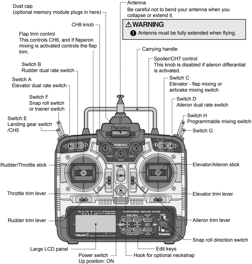
Rudder/Throttle stick
Throttle trim lever
Rudder trim lever
Large LCD panel
Power switch Up position: ON
Elevator/Aileron stick
Elevator trim lever
Aileron trim lever
Snap roll direction switch
Edit keys
Hook for optional neckstrap
This figure shows the default assignments for a Mode 2 system as supplied by the factory. You can change many of the switch positions or functions by selecting a new position within the setting menu for the function you wish to move.
8
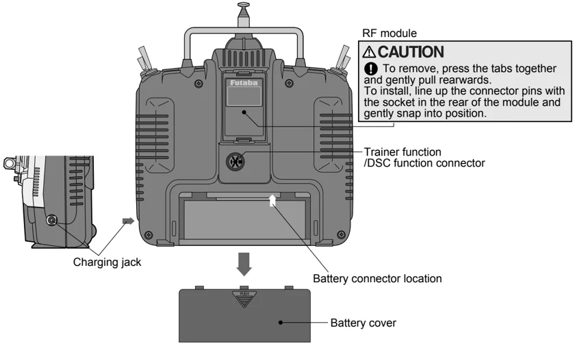
NOTE: If you need to remove or replace the transmitter battery, do not pull on its wires to remove it. Instead, gently pull on the connector’s plastic housing where it plugs in to the transmitter.
SWITCH ASSIGNMENT TABLE
The factory default functions activated by the switches and knobs for a Mode 2 transmitter are shown below. Note that some of the functions will not operate until activated in the mixing menus. In general, functions for a Mode 1 transmitter reverse the E and G switches.
| Switch / Knob | ACRO | GLID | HELI |
|---|---|---|---|
| Switch A | Elevator Dual Rate | Elevator Dual Rate↓ = Butterfly on | Elevator Dual Rate↓ = PMIX-1, 2 on |
| Switch B | Rudder Dual Rate | Rudder Dual Rate | Rudder Dual Rate |
| Switch C | ↑ = ELE→FLP oncenter/↓ = Idle-down↓ = Airbrake on | ↑ = ELE→FLP oncenter/↓ = Idle-down↓ = PMIX-5 on | CH 7 |
| Switch D | Aileron Dual Rate | Aileron Dual Rate | Aileron Dual Rate |
| Switch E | Landing Gear | GLID1FLP: Gear | fwd = Throttle Hold |
| Switch F | Snap Roll/Trainer | Trainer | Trainer |
| Switch G | ↓ = PMIX-5 on | back = Speedforward = Start (Launch) | Idle-up |
| Switch H | ↓ = PMIX-1, -2, -3 on | ↓ = PMIX-1, -2, -3 on | Inverted/CH5 |
| CH6 knob | Flap(Flap trim if FLPRON on) | GLID1FLP: Flap(Flap trim if FLPRON on)GLID2FLP: Camber(Flap trim if FLP-AI off) | Hovering Pitch |
| CH7 knob | Spoiler(disabled if AI-DIF on) | Spoiler(disabled if AI-DIF on) | Hovering Throttle |
| CH8 knob | CH8 | CH8 | CH8 |
9
CHARGING THE Ni-Cd BATTERIES
Charging. Your. System.s. Batteries
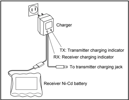
- Connect the transmitter charging jack and airborne Ni-Cd batteries to the transmitter and receiver connectors of the charger.
- Plug the charger into a wall socket.
- Check that the charger LED lights. The batteries should be left on charge for about 15 hours when recharging the standard NR-4J and NT8S600B Ni-Cd batteries.
CAUTION
use of a fast charger may damage the batteries by overheating and dramatically reduce their lifetime.
You should fully discharge your system’s batteries periodically to prevent a condition called “memory.” For example, if you only make two flights each session, or you regularly use only a small amount of the batteries’ capacity, the memory effect can reduce the actual capacity even if the battery is fully charged. You can cycle your batteries with a commercial cycling unit, or by leaving the system on and exercising the servos by moving the transmitter sticks. Cycling should be done every four to eight weeks, even during the winter or periods of long storage. Keep track of the batteries’ capacity during cycling; if there is a noticeable change, you may need to replace the batteries.
Adjusting the length of the non-slip control sticks
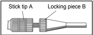
You may change the length of the control sticks to make your transmitter more comfortable to hold and operate. To lengthen or shorten your transmitter’s sticks, first unlock the stick tip by holding locking piece B and turning stick tip A counterclockwise. Next, move the locking piece B up or down (to lengthen or shorten). When the length feels comfortable, lock the position by turning locking piece B counterclockwise.
10
Stick lever tension adjustment
You may adjust the stick tension of your sticks to provide the “feel” that you like for flying. To adjust your springs, you’ll have to remove the rear case of the transmitter. First, pop off the battery cover on the rear of the transmitter. Next, unplug the battery wire, and remove the battery and RF module from the transmitter. While you’re removing the RF module, pay attention to the location of the pins that plug into the back of the module. Next, using a screwdriver, remove the four screws that hold the transmitter’s rear cover into position, and put them in a safe place. Gently ease off the transmitter’s rear cover. Now you’ll see the view shown in the figure below.
Using a small screwdriver, rotate the adjusting screw for each stick for the desired spring tension. The tension increases when the adjusting screw is turned clockwise, and decreases for counterclockwise motion.
When you are satisfied with the spring tensions, you may close the transmitter. Check that the upper printed circuit board is on its locating pins, then very carefully reinstall the rear cover being careful thread the RF module connector pins through the hole in the case and not to bend them. When the cover is properly in place, tighten the four screws.
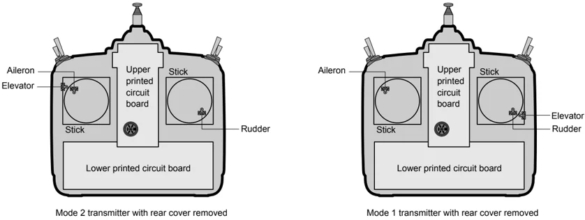
Mode 2 transmitter with rear cover removed
Mode 1 transmitter with rear cover removed
Changing the 8UA transmitter's mode
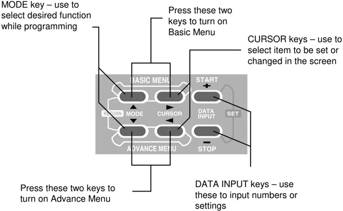
If you wish to change the mode of the transmitter, say from mode 1 to mode 2, turn on the transmitter holding the two MODE buttons down. You’ll see a display “STICK MODE X,” where X is a number representing the current transmitter mode. Press the plus (+) or minus (–) DATA INPUT key to change the mode number as desired. You’ll see the effect of you changes when you next turn on your transmitter. In some cases, you’ll have to swap the throttle detent mechanism with the elevator centering mechanism. This can be done by Futaba.
STICK MODE 2
11
RECEIVER AND SERVO CONNECTIONS
| Receiver output channel | Aircraft (ACRO) | Glider (GLID1FLP /GLID2FLP) | Helicopter (HELI) |
|---|---|---|---|
| 1 | Right aileron (combined R. flap + aileron*) | Right aileron | Aileron |
| 2 | Elevator | Elevator | Elevator |
| 3 | Throttle | Motor/Speed Control | Throttle |
| 4 | Rudder | Rudder | Rudder |
| 5 | Landing Gear | Right Flap | Gyro sensitivity |
| 6 | Left aileron (combined L. flap + aileron*) | Left flap (Left aileron*) | Pitch |
| 7 | Spare | Left aileron Left aileron† | Spare |
| 8 | Spare | Spare | Spare |
Multiple entries indicate that the servo function varies with the selected programming (*=FLPRON mode, †=AI-DIF mode). Outputs with no mixing functions are shown first.
The diagram below shows the default connections in the ACRO mode.
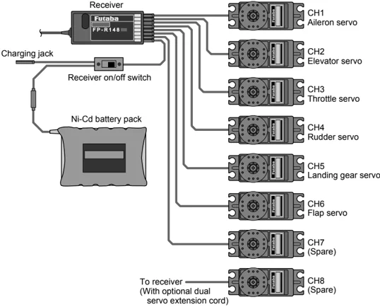
Receiver Notes
⚠️ CAUTION
vertical fin, and let the excess length trail behind the aircraft.
• When you insert servo or battery connectors into the receiver, note that each plastic housing has an alignment tab. Be sure the alignment tab is oriented properly before inserting the connector. To remove a connector from the receiver, pull on the connector housing rather than the wires.
• If your aileron servo (or others) are too far to plug into the receiver, use an aileron extension cord to extend the length of the servo lead. Additional extension cords of varying lengths are available from your hobby dealer or Futaba.
12
RADIO INSTALLATION
CAUTION While you are installing the battery, receiver, and servos into your model’s fuselage, please pay attention to the following guidelines:
Servo Mounting
❗ Use the supplied rubber grommets when you mount each servo. Be sure not to overtighten the screws. If any portion of the servo case directly contacts the fuselage or the servo rails, the rubber grommets will not attenuate vibration, which can cause mechanical wear and servo failure.
 Wood screw
Rubber grommet
Brass eyelet
Servo mount or rail
Servo Throw
❗ Once you have installed the servos, operate each one over its full travel and check that the pushrod and output arms do not bind or collide with each other, even at extreme trim settings. Check to see that each control linkage does not require undue force to move (if you hear a servo buzzing when there is no transmitter control motion, most likely there is too much friction in the control or pushrod). Even though the servo will tolerate loads, any unnecessary load applied to the servo arm will drain the battery pack quickly.
Switch Harness Installation
❗ When you are ready to install the switch harness, remove the switch cover and use it as a template to cut screw holes and a rectangular hole slightly larger than the full stroke of the switch. Choose a switch location on the opposite side of the fuselage from the engine exhaust pipe, and pick a location so that it can’t be inadvertently turned on or off during handling or storage. Install the switch so that it moves without restriction and “snaps” from ON to OFF and vice versa.
Receiver Antenna
It is normal for the receiver antenna to be longer than the fuselage.
🚫 DO NOT cut it or fold it back on itself – cutting or folding changes the electrical length of the antenna and may reduce range. Secure the antenna to the top of the vertical fin, and let the excess wire length trail behind. You may run the antenna inside of a non-metallic housing within the fuselage, but range may suffer if the antenna is located near metal pushrods or cables. Be sure to perform a range check before flying.
Receiver Vibration and Waterproofing
The receiver contains precision electronic parts. Be sure to avoid vibration, shock, and temperature extremes.
❗ For protection, wrap the receiver in foam rubber or other vibration-absorbing materials. It’s also a good idea to waterproof the receiver by placing it in a plastic bag and securing the open end of the bag with a rubber band before wrapping it with foam. If you accidentally get moisture inside the receiver, you may experience intermittent operation or a crash.
13
Airplane Frequencies
The following frequencies and channel numbers may be used for flying aircraft in the United States:
72 MHz band
| Ch. No. | MHz | Ch. No. | MHz |
|---|---|---|---|
| 11 | 72.010 | 36 | 72.510 |
| 12 | 72.030 | 37 | 72.530 |
| 13 | 72.050 | 38 | 72.550 |
| 14 | 72.070 | 39 | 72.570 |
| 15 | 72.090 | 40 | 72.590 |
| 16 | 72.110 | 41 | 72.610 |
| 17 | 72.130 | 42 | 72.630 |
| 18 | 72.150 | 43 | 72.650 |
| 19 | 72.170 | 44 | 72.670 |
| 20 | 72.190 | 45 | 72.690 |
| 21 | 72.210 | 46 | 72.710 |
| 22 | 72.230 | 47 | 72.730 |
| 23 | 72.250 | 48 | 72.750 |
| 24 | 72.270 | 49 | 72.770 |
| 25 | 72.290 | 50 | 72.790 |
| 26 | 72.310 | 51 | 72.810 |
| 27 | 72.330 | 52 | 72.830 |
| 28 | 72.350 | 53 | 72.850 |
| 29 | 72.370 | 54 | 72.870 |
| 30 | 72.390 | 55 | 72.890 |
| 31 | 72.410 | 56 | 72.910 |
| 32 | 72.430 | 57 | 72.930 |
| 33 | 72.450 | 58 | 72.950 |
| 34 | 72.470 | 59 | 72.970 |
| 35 | 72.490 | 60 | 72.990 |
50 MHz Band (Amateur license required)
| Ch. No. | MHz | Ch. No. | MHz |
|---|---|---|---|
| 00 | 50.80 | 01 | 50.82 |
| 02 | 50.84 | 03 | 50.86 |
| 04 | 50.88 | 05 | 50.90 |
| 06 | 50.92 | 07 | 50.94 |
| 08 | 50.96 | 09 | 50.98 |
▲ CAUTION
Installing your frequency number indicator:
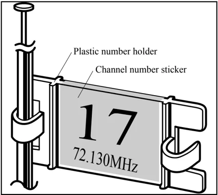
● It’s very important that you display your transmitting channel number at all times. To install your indicator, peel off the channel number’s backing sheet, and carefully stick the numbers to both sides of the number holder. Now you can snap the number holder onto the lower portion of the antenna as shown in the figure – use the clip that fits more snugly on your antenna. You may wish to cut off the other, unused clip on the indicator.
14
TRANSMITTER DISPLAYS & BUTTONS
When you first turn on your transmitter, a confirmation beep sounds, and the screen shown below appears. Before flying, or even starting the engine, BE SURE that the model name appearing on the display matches the model that you are about to fly! If you don't, servos may be reversed, and travels and trims will be wrong, leading to an immediate crash.
Startup Screen (appears when system is first turned on)
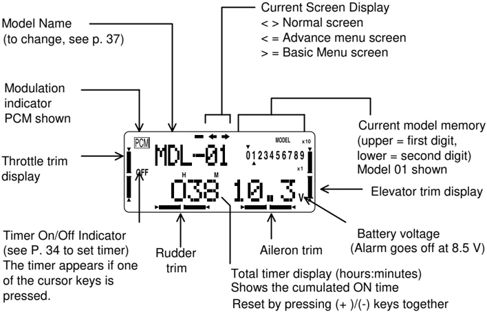
Note: trim display can be displayed in reverse video (see page 39)
Edit keys
15
WARNING & ERROR DISPLAYS
An alarm or error indication may appear on the display of your transmitter for several reasons, including when the transmitter power switch is turned on, when the battery voltage is low, and several others. Each display has a unique sound associated with it, as described below.
BACKUP ERROR
Warning sound: Beep beep beep beep (repeated)
The BACKUP ERROR warning occurs when the transmitter memory is lost for any reason. If this occurs, all of the data will be reset when the power is turned on again.
⚠WARNING 🚫 DO NOT FLY when this message is displayed – all programming has been erased and is not available. Return your transmitter to Futaba for service.
MODEL SELECTION ERROR
Warning sound: Beep beep beep beep beep (repeated 3 times)
The MODEL SELECTION warning is displayed when the transmitter attempts to load a model memory from a memory module that is not currently plugged into the transmitter. When this occurs, model No. 01 is automatically loaded.
⚠WARNING 🚫 Do not fly until the proper model is loaded into memory! Reinsert the memory module, and recall the desired setup using the model select function.
LOW BATTERY ERROR
Warning sound: Beep beep beep — (beeping does not stop until transmitter is turned off)
The LOW BATTERY warning is displayed when the transmitter battery voltage drops below 8.5V.
⚠WARNING ❗ LAND YOUR MODEL AS SOON AS POSSIBLE BEFORE LOSS OF CONTROL DUE TO A DEAD BATTERY.
MIXER ALERT WARNING
Warning sound: beep beep beep beep beep space (repeated)
The MIXER ALERT warning is displayed to alert you whenever you turn on the transmitter with any of the mixing switches active. This warning will disappear when the offending switch or control is deactivated. Switches for which warnings will be issued at power-up are listed below: ACRO: Throttle cut, idle-down, snap roll, airbrake GLID: Butterfly, throttle cut, idle-down HELI: Throttle cut, inverted, throttle hold, idle-up
(Operation when switch OFF does not stop the mixing warning) When the warning does not stop even when the mixing switch indicated by the warning display on the screen is turned off, the functions described above probably use the same switch and the OFF direction setting is reversed. In short, one of the mixings described above is not in the OFF state. In this case, reset the warning display by pressing (+)/(-) keys simultaneously. Then change one of the switch settings of the mixings duplicated at one switch.
16
MEMORY MODULE INITIALIZE DISPLAY
This warning appears when an [optional] CAMPac memory module is used in the transmitter for the first time. When the Plus (+) DATA INPUT key is pressed, initialization of the module begins, after which the memory module can be used. Once the module is initialized, the display will not appear again.
RF MODULE WARNING
Warning sound: A single beep
This single beep lets you know that the RF module is not installed in the transmitter.
17
18
AIRCRAFT (ACRO) MENU FUNCTIONS
*Pages 19 to 40 describe the Basic Menu functions for fixed-wing aircraft. Please note that all of these Basic Menu functions are the same for aircraft (ACRO setup), sailplanes (GLID1FLP/2FLP setups), and helicopter (HELISWH1/SWH2/SWH4/SR-3/SN-3) setups as well.
-
Map of Basic Aircraft Functions ........ 19
-
Map of ACRO Advance Menu Functions ........ 20
-
Aircraft Setup Example ........ 22
-
Pattern Aircraft Trimming Chart ........ 24
-
ATV ........ Adjustable Travel Volume ........ 26
-
D/R ........ Dual rate ........ 26
-
EXP ........ Exponential ........ 28
-
IDL-DN ........ Idle-down ........ 29
-
F/S ........ Fail safe ........ 29
-
REVERS ........ Servo reverse ........ 30
-
PARA ........ Parameters ........ 31
-
DATARSET Data reset ........ 31
-
ATL ........ ATL trim ........ 31
-
EG/S ........ Engine starter ........ 32
-
TYPE ........ Model type ........ 32
-
MOD ........ Modulation ........ 34
-
AIL2 ........ Second aileron ........ 34
-
TRAINR ........ Trainer ........ 35
-
MODEL ........ Model ........ 36
-
SEL ........ Model selection ........ 36
-
COPY ........ Model copy ........ 36
-
NAME ........ Model name ........ 37
-
TRIM ........ Trim ........ 38
-
RSET ........ Trim reset ........ 38
-
STEP ........ Trim step ........ 38
-
DISP ........ Trim reverse display ........ 39
-
SUBTRM ........ Subtrim ........ 39
-
TH-CUT ........ Throttle cut ........ 40
-
TIMER ........ Timer ........ 40
19
MAP OF ACRO AIRCRAFT FUNCTIONS
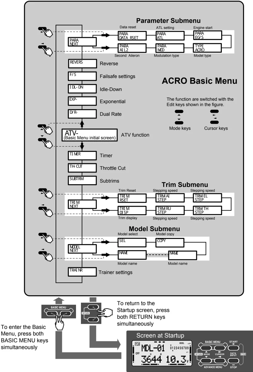
Parameter Submenu
| Data reset | ATL setting | Engine start |
|---|---|---|
| PARA DATA RSET | PARA ATL | PARA EG/S |
| PARA NEXT | PARA ATL2 | PARA MOD |
| Second Aileron | Modulation type | Model type |
ACRO Basic Menu
REVERS | Reverse F/S | Failsafe settings IDL-DN | Idle-Down EXP- | Exponential D/R- | Dual Rate
The function are switched with the Edit keys shown in the figure.
ATV- (Basic Menu initial screen) | ATV function
Mode keys | Cursor keys
TIMER | Timer TH-CUT | Throttle Cut SUBTRM | Subtrims
Trim Submenu
| Trim Reset | Stepping speed | Stepping speed |
|---|---|---|
| TRIM RSET | TRM AI STEP | TRM EL STEP |
| TRIM NEXT | TRM DISP | TRM RU STEP |
| Trim display | Stepping speed | Stepping speed |
Model Submenu
| Model select | Model copy |
|---|---|
| SEL | COPY |
| MODEL NEXT | NAME |
| Model name | Model name |
TRAI NR | Trainer settings
To enter the Basic Menu, press both BASIC MENU keys simultaneously
To return to the Startup screen, press both RETURN keys simultaneously
Screen at Startup
20
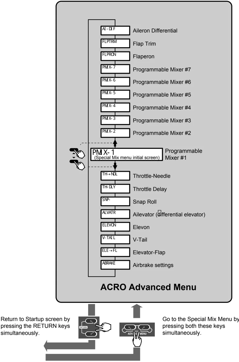
Return to Startup screen by pressing the RETURN keys simultaneously.
Go to the Special Mix Menu by pressing both these keys simultaneously.
21