FLAPTRM — Flap Trim (Camber)
The Flap Trim function is used to specify the amount of flap travel (or camber, if on a sailplane setup). If flaperon (FLPRON) mixing is active, FLAPTRM is automatically turned on. You should match the travel of both flaps before using this function to set the total amount of flap throw. The amount depends on the model, but for sailplanes a small amount (less than 10%) is preferred, since too much camber produces excessive drag. Don’t use more than about 1/16” travel up or down (some airfoils, such as the RG-15, should be flown with NO reflex).
Setting Flap Trim function
Turn the FLPTRM function ON or OFF by pressing the (+) key ("ON" displayed). Turn off (INH) the function with the (-) key.
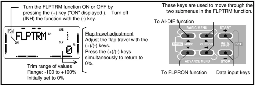
Trim range of values Range: -100 to +100% Initially set to 0%
These keys are used to move through the two submenus in the FLPTRM function.
To AI-DIF function
To FLPRON function
Data input keys
AI-DIF — Aileron Differential
The differential function allows you to program the amount of ‘up’ aileron travel independently from the amount of down travel when you have two servos plugged into the receiver (right aileron = CH1/AIL and left aileron = CH7).
NOTE: Only one of the three functions aileron differential, flaperon, or elevon can be used at a time. The last function activated overrides the others. If you need both flaperons and differential, activate the FLPRON function and in its menu set different up and down aileron travels to provide differential.
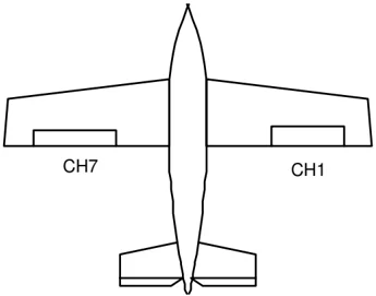
CH7
CH1
Setting up aileron differential in AI-DIF
Turn the AI-DIF function ON by pressing the (+) key ("ON" displayed). Turn off (INH) the function with the (-) key.
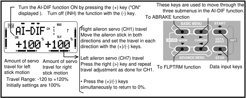
Amount of servo travel for left stick motion
Travel Range: -120 to +120%
Initially settings are 100%
Amount of servo travel for right stick motion
Right aileron servo (CH1) travel
Move the aileron stick in both directions and set the travel in each direction with the (+)/(-) keys.
Left aileron servo (CH7) travel
Press the right (>) key and repeat travel adjustment as done for CH1.
• Press the (+)/(-) keys simultaneously to return to 0%.
These keys are used to move through the three submenus in the AI-DIF function.
To ABRAKE function
To FLPTRM function
Data input keys
46
ABRAKE — Airbrake Function
The ABRAKE function simultaneously drops the flaps and moves the elevator, and may be used to make steep descents or limit airspeed in dives. Airbrakes can be activated in a proportional manner by moving the throttle stick, or you may choose to move all the controls to the defined positions by flipping switch C. If you choose to operate it by throttle stick motion, you'll need to set the stick position for it to be activated. You can suppress sudden changes in your model's attitude when airbrake is activated by setting the delay ("DLY") item, which slows down the elevator response.
When the FLPRON function has been selected, the travel of the ailerons when the airbrake is operated can be independently adjusted for the servos plugged into CH1 and CH6. When AI-DIFF function is used, the travel for CH1 and CH7 may be adjusted. Normally both ailerons are raised in the airbrake mode, and the elevator motion is selected to maintain trim when the ailerons rise.
Setting up Airbrake function
- Turn the ABRAKE function ON by pressing the (+) key ("ON" displayed). Turn off (INH) the function with the (-) key.
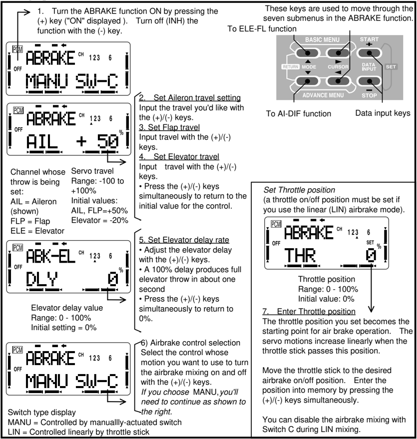
Channel whose throw is being set: AIL = Aileron (shown) FLP = Flap ELE = Elevator
Servo travel Range: -100 to +100% Initial values: AIL, FLP=+50% Elevator = -20%
These keys are used to move through the seven submenus in the ABRAKE function. To ELE-FL function To Al-DIF function Data input keys
-
Set Aileron travel setting Input the travel you'd like with the (+)/(-) keys.
-
Set Flap travel Input travel with the (+)/(-) keys.
-
Set Elevator travel Input travel with the (+)/(-) keys. • Press the (+)/(-) keys simultaneously to return to the initial value for the control.
-
Set Elevator delay rate • Adjust the elevator delay with the (+)/(-) keys. • A 100% delay produces full elevator throw in about one second • Press the (+)/(-) keys simultaneously to return to 0%.
Elevator delay value Range: 0 - 100% Initial setting = 0%
- Airbrake control selection Select the control whose motion you want to use to turn the airbrake mixing on and off with the (+)/(-) keys. If you choose MANU, you'll need to continue as shown to the right.
Switch type display MANU = Controlled by manuallylly-actuated switch LIN = Controlled linearly by throttle stick
Set Throttle position (a throttle on/off position must be set if you use the linear (LIN) airbrake mode).
Throttle position Range: 0 - 100% Initial value: 0%
- Enter Throttle position The throttle position you set becomes the starting point for air brake operation. The servo motions increase linearly when the throttle stick passes this position.
Move the throttle stick to the desired airbrake on/off position. Enter the position into memory by pressing the (+)/(-) keys simultaneously.
You can disable the airbrake mixing with Switch C during LIN mixing.
ELE→FL — Elevator-to-Flap Mixing
Elevator-to-flap mixing makes the flaps drop or rise whenever the elevator stick is moved. It is most commonly used to make tighter “pylon” turns or squarer corners in maneuvers. In most cases, the flaps droop (are lowered) when up elevator is commanded.
Setting Elevator-to-Flap Mixing
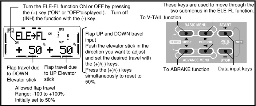
Turn the ELE-FL function ON or OFF by pressing the (+) key ("ON" or "OFF"displayed). Turn off (INH) the function with the (-) key.
These keys are used to move through the two submenus in the ELE-FL function.
To V-TAIL function
BASIC MENU START + RETURN MODE CURSOR DATA INPUT SET ADVANCE MENU STOP
To ABRAKE function Data input keys
Flap UP and DOWN travel input Push the elevator stick in the direction you want to adjust and set the desired travel with the (+)/(-) keys. Press the (+)/(-) keys simultaneously to reset to 50%.
Flap travel due to DOWN Elevator stick
Flap travel due to UP Elevator stick
Allowed flap travel Range: -100 to +100% Initially set to 50%
V-TAIL — V-Tail Mixing
V-tail mixing is used with V-tail aircraft so that both elevator and rudder functions are combined for the two tail surfaces. Both elevator and rudder travel can be adjusted independently on each surface. Because they share receiver outputs, Elevon and V-Tail mixing cannot be activated simultaneously.
Setting up V-Tail mixing
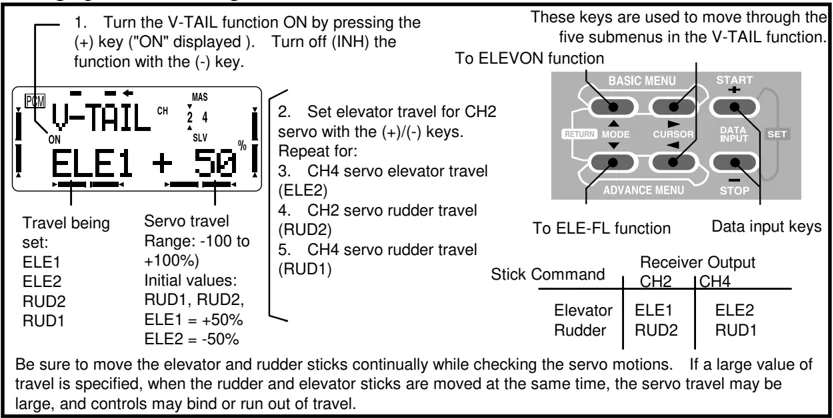
- Turn the V-TAIL function ON by pressing the (+) key ("ON" displayed). Turn off (INH) the function with the (-) key.
These keys are used to move through the five submenus in the V-TAIL function.
To ELEVON function
BASIC MENU START + RETURN MODE CURSOR DATA INPUT SET ADVANCE MENU STOP
To ELE-FL function Data input keys
- Set elevator travel for CH2 servo with the (+)/(-) keys. Repeat for:
- CH4 servo elevator travel (ELE2)
- CH2 servo rudder travel (RUD2)
- CH4 servo rudder travel (RUD1)
Travel being set: ELE1 ELE2 RUD2 RUD1
Servo travel Range: -100 to +100%) Initial values: RUD1, RUD2, ELE1 = +50% ELE2 = -50%
| Stick Command | Receiver Output CH2 | Receiver Output CH4 |
|---|---|---|
| Elevator | ELE1 | ELE2 |
| Rudder | RUD2 | RUD1 |
Be sure to move the elevator and rudder sticks continually while checking the servo motions. If a large value of travel is specified, when the rudder and elevator sticks are moved at the same time, the servo travel may be large, and controls may bind or run out of travel.
ELEVON — Elevon Mixing
The Elevon function should be used with delta wings, flying wings, and other tailless aircraft whose layouts combine the aileron and elevator functions, and requires one servo for each elevon. The aileron and elevator response of each servo can be adjusted independently. Connect the right aileron to receiver CH1/AIL and the left aileron to CH2/ELE.
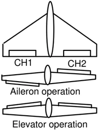
NOTE: The elevon, flaperon, aileron differential, and ailelevator functions cannot be activated simultaneously. The function activated last has priority.
Setting up elevon mixing
- Turn the ELEVON function ON by pressing the (+) key ("ON" displayed). Turn off (INH) the function with the (-) key.
To ALVATR function These keys are used to move through the FIVE submenus in the ELEVON function.
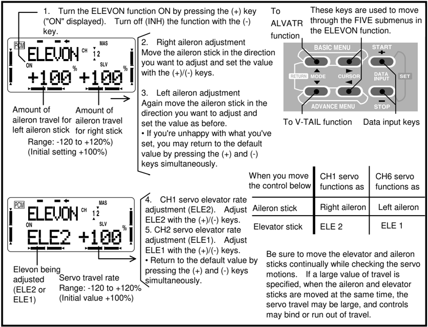
Amount of aileron travel for left aileron stick Range: -120 to +120%) (Initial setting +100%)
Amount of aileron travel for right stick
-
Right aileron adjustment Move the aileron stick in the direction you want to adjust and set the value with the (+)/(-) keys.
-
Left aileron adjustment Again move the aileron stick in the direction you want to adjust and set the value as before.
- If you're unhappy with what you've set, you may return to the default value by pressing the (+) and (-) keys simultaneously.
| When you move the control below | CH1 servo functions as | CH6 servo functions as |
|---|---|---|
| Aileron stick | Right aileron | Left aileron |
| Elevator stick | ELE 2 | ELE 1 |
Be sure to move the elevator and aileron sticks continually while checking the servo motions. If a large value of travel is specified, when the aileron and elevator sticks are moved at the same time, the servo travel may be large, and controls may bind or run out of travel.
- CH1 servo elevator rate adjustment (ELE2). Adjust ELE2 with the (+)/(-) keys.
- CH2 servo elevator rate adjustment (ELE1). Adjust ELE1 with the (+)/(-) keys.
- Return to the default value by pressing the (+) and (-) keys simultaneously.
Elevon being adjusted (ELE2 or ELE1) Servo travel rate Range: -120 to +120% (Initial value +100%)
ALVATR — Ailelevator Mixing
The Ailelevator mixing function allows you to connect two servos to the receiver that operate two independent elevator control surfaces together as elevators and differentially as ailerons. This may be used to get more realistic flying properties with jet fighters and similar aircraft. You may also use this mixing to drive dual elevator servo without differential. The elevator and aileron travel can be adjusted independently. The two elevator servos must be plugged into the receiver CH2 and CH8 outputs. NOTE: Ailelevator mixing cannot be activated simultaneously with the throttle→needle mixing function, because they use the same receiver channels.
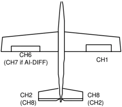
49
Setting up dual elevator servos
- Turn the ALVATR function ON by pressing the (+) key ("ON" displayed). Turn off (INH) the function with the (-) key.
- CH2 tail servo aileron travel adjustment (AIL3): enter the desired value with the (+)/(-) keys.
- CH8 tail servo aileron travel adjustment (AIL4): adjust and set the value as before.
- CH8 tail servo elevator rate adjustment (ELE2) Adjust the rate with the (+)/(-) keys.
- CH2 tail servo elevator rate adjustment (ELE1) • Return to the default by pressing the (+) and (-) keys simultaneously.
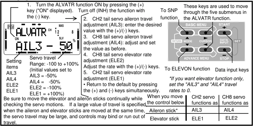
Be sure to move the elevator and aileron sticks continually while checking the servo motions. If a large value of travel is specified, when the aileron and elevator sticks are moved at the same time, the servo travel may be large, and controls may bind or run out of travel.
To SNP function These keys are used to move through the five submenus in the ALVATR function.
To ELEVON function Data input keys
If you want elevator function only, set the "AIL3" and "AIL4" travel rates to 0.
| When you move the control below | CH2 servo functions as | CH8 servo functions as |
|---|---|---|
| Aileron stick* | AIL3 | AIL4 |
| Elevator stick | ELE1 | ELE2 |
SNP — Snap Roll
This function may be programmed so that you may execute snap rolls by flipping a switch. You may select any of four roll directions using switches on the front panel of the transmitter, and can set up a safety switch to prevent accidental snap rolls while the landing gear is down, even if you accidentally activate the snap roll switch. You cannot do snaps while using the trainer function.
SETTING METHOD
- Turn the SNP function ON by pressing the (+) key Turn off (INH) the function with the (-) key. Move the transmitter front panel snap roll direction switch to the direction you want to set
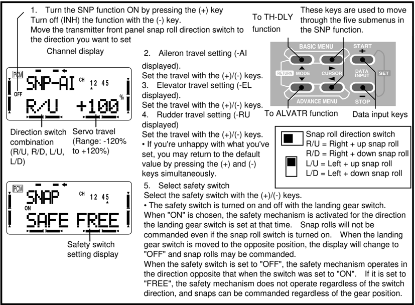
Direction switch combination (R/U, R/D, L/U, L/D) Servo travel (Range: -120% to +120%)
Safety switch setting display
- Aileron travel setting (-AI displayed). Set the travel with the (+)/(-) keys.
- Elevator travel setting (-EL displayed). Set the travel with the (+)/(-) keys.
- Rudder travel setting (-RU displayed) Set the travel with the (+)/(-) keys. • If you're unhappy with what you've set, you may return to the default value by pressing the (+) and (-) keys simultaneously.
- Select safety switch Select the safety switch with the (+)/(-) keys. • The safety switch is turned on and off with the landing gear switch. When "ON" is chosen, the safety mechanism is activated for the direction the landing gear switch is set at that time. Snap rolls will not be commanded even if the snap roll switch is turned on. When the landing gear switch is moved to the opposite position, the display will change to "OFF" and snap rolls may be commanded. When the safety switch is set to "OFF", the safety mechanism operates in the direction opposite that when the switch was set to "ON". If it is set to "FREE", the safety mechanism does not operate regardless of the switch direction, and snaps can be commanded regardless of the gear position.
To TH-DLY function These keys are used to move through the five submenus in the SNP function.
To ALVATR function Data input keys
Snap roll direction switch R/U = Right + up snap roll R/D = Right + down snap roll L/U = Left + up snap roll L/D = Left + down snap roll
50
TH-DLY — Throttle Delay
The Throttle Delay function is used to delay the response of the throttle servo to simulate the slow response of a turbojet engine to throttle control. A 40% delay setting corresponds to about a one second delay, while a 100% delay takes about eight seconds to respond.
Setting Throttle delays
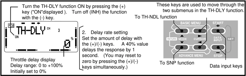
Turn the TH-DLY function ON by pressing the (+) key ("ON" displayed). Turn off (INH) the function with the (-) key.
Throttle delay display Delay range: 0 to +100% Initially set to 0%
These keys are used to move through the two submenus in the TH-DLY function. To TH-NDL function To SNP function Data input keys
- Delay rate setting Set the amount of delay with the (+)/(-) keys. A 40% value delays the response by 1 second. (You may reset to zero by pressing the (+)/(-) keys simultaneously.)
TH→NDL — Throttle Needle Mixing
The throttle needle mixing function is used to control the motion a second servo connected to the mixture control system of an engine (needle valve or other mixture adjustment) relative to throttle stick movement. The throttle needle servo connects to receiver CH8, and the CH8 control knob adjusts the high throttle mixture. An acceleration function moves the engine mixture control when the throttle is moved. This function cannot be used simultaneously with the Ailevator function.
SETTING METHOD
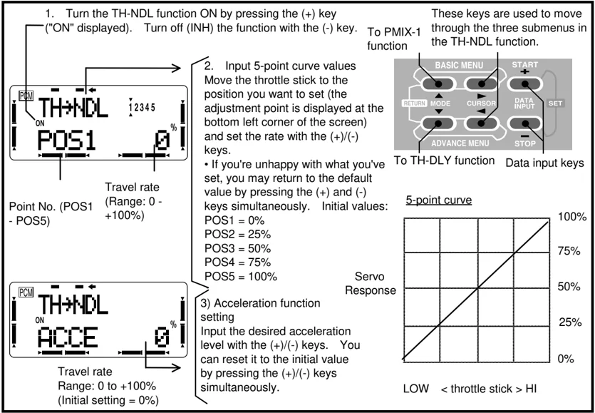
- Turn the TH-NDL function ON by pressing the (+) key ("ON" displayed). Turn off (INH) the function with the (-) key.
Point No. (POS1 - POS5) Travel rate (Range: 0 - +100%)
- Input 5-point curve values Move the throttle stick to the position you want to set (the adjustment point is displayed at the bottom left corner of the screen) and set the rate with the (+)/(-) keys.
- If you're unhappy with what you've set, you may return to the default value by pressing the (+) and (-) keys simultaneously. Initial values: POS1 = 0% POS2 = 25% POS3 = 50% POS4 = 75% POS5 = 100%
These keys are used to move through the three submenus in the TH-NDL function. To PMIX-1 function To TH-DLY function Data input keys
- Acceleration function setting Input the desired acceleration level with the (+)/(-) keys. You can reset it to the initial value by pressing the (+)/(-) keys simultaneously.
Travel rate Range: 0 to +100% (Initial setting = 0%)
5-point curve Servo Response LOW < throttle stick > HI
51
GLIDER (GLID1FLP/2FLP) ADVANCE MENU FUNCTIONS
The pages in the glider Advance Menu section describe the additional special mixing functions that only are available when the two glider (GLID1FLP, GLID2FLP) model types are selected. The GLID1FLP menu is intended for sailplanes with one or two aileron servos, and a single flap servo (or two connected with a y-connector), while the -2FLP configuration is for dual flap servos that can act oppositely as ailerons. Note that for some aerobatic and slope gliders, the ACRO menus may be more appropriate to use, as they provide snap rolls.
For an explanation of the other Advance Menu functions available in the GLID menus, refer to the aircraft (ACRO) Advance Menu section, p. 43 to 51.
If you wish to have the three-position switch controlling Normal, Start, and Speed on the left-hand side of the transmitter, you should purchase the 8UH Helicopter system. The 8UA system places it on the right-hand side.
-
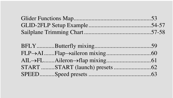
Glider Functions Map ........ 53
-
GLID-2FLP Setup Example ........ 54-57
-
Sailplane Trimming Chart ........ 57-58
-
BFLY ........ Butterfly mixing ........ 59
-
FLP→AI ........ Flap→aileron mixing ........ 60
-
AIL→FL ........ Aileron→flap mixing ........ 61
-
START ........ START (launch) presets ........ 62
-
SPEED ........ Speed presets ........ 63
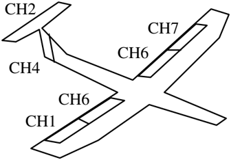
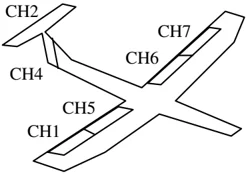
CH2 CH7 CH6 CH4 CH6 CH1 Glider 1FLP Configuration
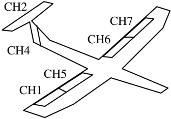
CH2 CH7 CH6 CH4 CH5 CH1 Glider 2FLP Configuration
52
8UA GLIDER (GLID1FLP, GLID2FLP) FUNCTIONS MAP
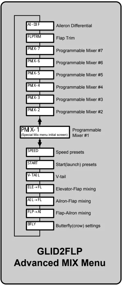
The Advanced Menus for the GLID1FLP and GLID2FLP are shown below. The Basic Menu for both of these model types is identical to that shown for aircraft (ACRO) on p. 20.
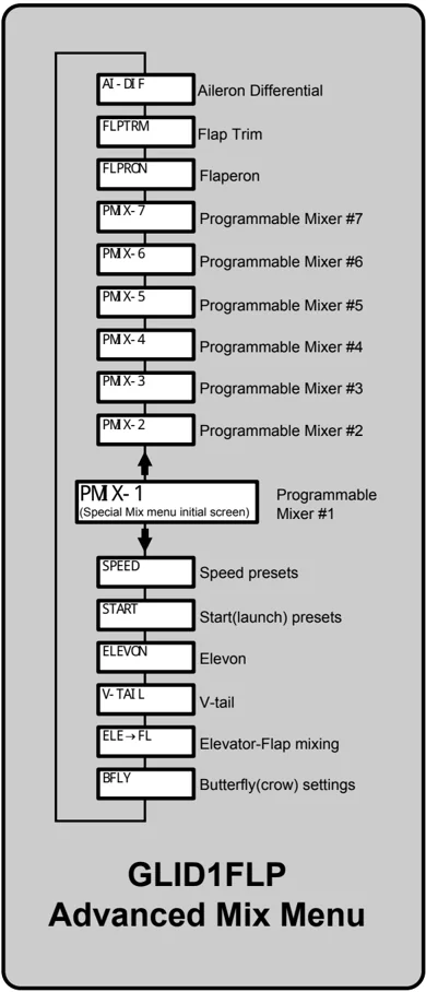
GLID1FLP Advanced Mix Menu
GLID2FLP Advanced MIX Menu
53
GLID-2FLP SETUP INSTRUCTIONS (TWO AILERON & TWO FLAP SERVOS)
- Before you begin, be sure that all of your aileron and flap servos are plugged into the proper receiver channels. This example assumes that you are using model memory #3. CH1 — Right aileron CH2 — Elevator (or first half of v-tail) CH3 — (not used) CH4 — Rudder (or second half of v-tail) CH5 — Right Flap CH6 — Left Flap CH7 — Left Aileron
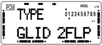
- Enter the BASIC SETUP mode by pressing the two BASIC buttons simultaneously. Press the UP or Down mode keys until you get to the PARA menu. Press the left CURSOR button to advance to TYPE setup, which should display GLID2FLP. If it doesn’t, then press either of the DATA INPUT buttons until the words GLID 2FLP are displayed. Press both the DATA INPUT buttons to activate the mode. “OK ?” will appear flashing in the upper left of the display. Pressing both the DATA INPUT buttons again will lock in the selected mode. CAUTION: AS SOON AS YOU SWITCH THE MODEL MODE, SOME OR ALL OF THE DATA EXISTING IN THE CURRENT MODEL MEMORY WILL BE ERASED! (The other seven memories will not be affected.)
- Do not worry that the servos may not be moving the proper direction now. We will first activate all the special mixes necessary, and later go to the reverse menu to correct any reversed servo responses (if necessary).
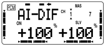
Press the ADVANCE buttons to get to the Advance Menus. This is where are the sailplane-specific mixers are located. Press either of the MODE keys to get to the aileron differential (AI-DIF) settings menu. Activate this mode by pressing the plus (+) DATA INPUT key (the ‘ON’ symbol will be flashing). This makes the second aileron servo (CH7) operate. Ignore the number settings for now.
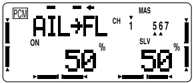
- Move to Aileron→Flap menu (AIL-FL, p 61). Activate it by pressing the Plus (+) DATA INPUT key ('ON' should be flashing). Use the Right (>) CURSOR key to get the left-hand number flashing, then use the plus (+) DATA INPUT key to set a value of 50%. Move the aileron stick to get the other number flashing, and set to the same number. You can increase this setting later if you need more maneuverability, such as for a slope racer or F3B model.
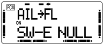
Now you may choose whether you want this mix always on or switchable. By hitting the Right (>) CURSOR key, you will see a display indicating Switch E controls this function, and the setting of the switch. NULL means always on, UP means on when Switch E is up, and DOWN means on when Switch E is down. We recommend leaving it in the NULL position; you can change the switch setting by pressing the (+) or (–) DATA INPUT keys.
-
If your model has a V-tail, go to the V-TAIL menu (p. 41) and activate it. This will make the elevator and rudder commands mix to the two tail surfaces. Leave the settings as is for now.
-
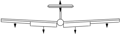
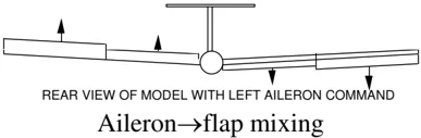
Now move the aileron stick to the left. You should see your model’s servos deflect as shown in the rear view below. The Right aileron and flap should move down, and the Left aileron and flap should go up. If the wing servos move as specified, you can continue.
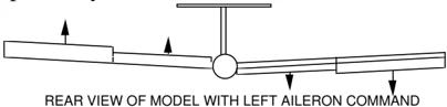
REAR VIEW OF MODEL WITH LEFT AILERON COMMAND
54
Reverse any of CH1, 5, 6, and 7 by moving to the appropriate channel number with the right or left CURSOR keys, then pressing the minus (–) or Plus (+) DATA INPUT key to reverse or unreverse the channel. Be sure you get the aileron response in the picture.
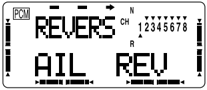
Next, move the elevator stick and be sure that the elevator moves the correct directions. Reverse CH 2 if necessary. Similarly check the response of the rudder (CH4). If you have a V-tail, you should get the following response for rudder and elevator commands:
Up elevator command Left Rudder command
-
Double-check to make sure all the servos move the correct way! Then, go to the ATV menu and specify the maximum servo throws while moving all the controls. Spend some time getting the correct motions in this step.
-
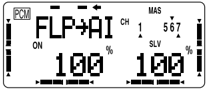
Move to the flap→aileron (FLP→AI, p. 60) menu, and activate by pressing the Plus (+) DATA INPUT key. Use a setting of 100% so the motion of all four wing servos is the same with flap and aileron horns that are the same length. If the horn lengths differ (hopefully in pairs) you can use a number either greater or less than 100% depending on the length ratio. The camber changing is done by turning the leftmost knob on the top center of the transmitter (CH. 6 flap trim knob).
- To set the amount of camber-changing across the wing, go to the flap trim menu (FLPTRM, p. 39) and activate it by pressing the Plus (+) DATA INPUT key. Set it to a small number (about 5%), or set it to zero if you want no camber-changing (this may be changed later for more travel). For cruising, you'll want no droop at all, but for slow-speed thermalling, you may want to droop the trailing edge a bit. Use the flap trim setting to get the desired amount of camber. No more that about 1/8" (3 mm) is all that is needed for most models.
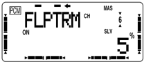
Note that the motion dictated by the Camber knob (CH. 6 flap trim knob) goes into both positive and negative camber from the neutral point, unless you set the F→A offset (see previous step). Also, note that if you don't set a small number or leave it inhibited (its default condition), you get HUGE motion of the trailing edge. You can set the approximate neutral point by matching the notch on the front of the knob with the slot in the knob holder.
- Put the camber knob (CH. 6 flap trim knob, on the top left of the transmitter) where you want it to be for normal flight, and make sure that the travel you desire is the right direction from that point. Be sure to center all of the trims, and get all of the servo arms to be near neutral. Use the clevises to get as close as you can. This way you won't run out of subtrim authority. Now set all the subtrims (SUBTRM, p. 39) to the desired neutral locations.
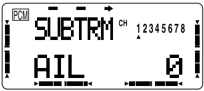
You can set the neutrals for the ailerons and flaps by using the foam wing beds or matching up with the rest of the wing. Don't use the fuselage airfoil (if any) as these are often not aligned properly. Set the elevator incidence per the plans/instructions, and center the rudder.
- Go back to differential (AI-DIF) and set to get more 'up' throw than 'down' on the ailerons. For starters, use a down travel of about 50% of the up travel. Your model may have different plus and minus signs depending on the servo orientations. Note that you set the right aileron's travel in both directions (move stick to change flashing display), then go to the left aileron's menu and repeat inputting values. CH 1 (right) aileron:
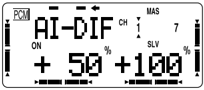
Right aileron down travel Right aileron up travel
55
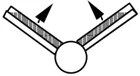
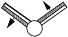
CH 7 (left) aileron:
 Left aileron up travel Left aileron down travel
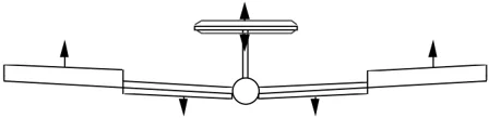
- Set up the butterfly (also referred to as “crow”) function for glide path control and precise spot landings. The ailerons go up and the flaps drop with movement of the throttle stick. Turn on the BFLY function (p. 59) by pressing the Plus (+) DATA INPUT KEY. The ‘ON’ display will be flashing unless switch A is up, then OFF will flash.
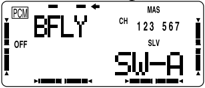
First set the Butterfly function activation point. Hit the Left (<) CURSOR key one time to get to the BFLY offset setting menu. Now move the throttle stick to where you want the function to begin. (we recommend having the throttle stick all the way up for normal flight, and have the BFLY function “kick in” about 3 clicks from top. This way, if you accidentally jog the throttle stick a bit, you won’t activate the butterfly function.) Enter your position by pressing the two DATA INPUT keys simultaneously.
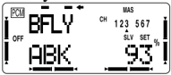
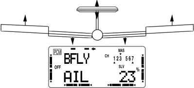
Next, hit the right (>) button until the AIL setting menu appears. Input a 25% value for the ailerons. Move the throttle stick and be sure the ailerons go UP with butterfly (see figure below). If they don’t, change the sign of the number you’ve chosen (this may depend on servo orientation). You’ll probably want 1/4 to 1/3 of aileron travel so you’ll have plenty of roll authority while on approach in full butterfly command. Notice that you set the throw for both ailerons at the same time: this is the reason to have identical control arm lengths and neutral positions.
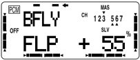
Hit the (>) CURSOR key once and input the throw for the flaps. Move the throttle stick and be sure the flaps DROP with butterfly. If they don’t, change the sign (this again may depend on servo orientation). You want as much flap motion as possible — 90° is great if you can get it. Like the ailerons, you set both flap offsets at the same time.
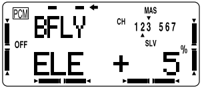
Use zero or very little elevator compensation until you fly and determine what is needed: if the model pitches up with butterfly, add down elevator compensation and vice versa. Make only small changes in compensation because it has a big effect on trim. Refer to the sailplane trimming chart for more details.
- Set up the START (launch, p.62) preset for high launches so that the flaps drop slightly lower than the ailerons to reduce tip-stalling tendencies. Recommended settings are 30%, 0%, 40%, 40%, 30%. Increase the up-elevator preset in small increments until the plane launches as steeply as you like; add down elevator if the model weaves back and forth or is hard to control (remember to use the rudder stick, or rudder coupling, during the launch). A well-trimmed model may actually have some down elevator mixed in for launching.
Remember that to get the START function to turn on, you have to flip the START/SPEED switch (Switch C, over the right-hand stick) to its lower position.
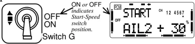
- You may also set up the speed mode presets (SPEED, p. 63) for high-speed cruise between thermals. Reflex (raise) the entire trailing edge no more than 1/16" (1.5 mm), or you’ll gain more drag than penetration ability. Use no more than 5 or 10% for initial setup.
56
 ON or OFF indicates Start-Speed switch position.
Switch G
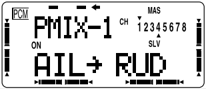
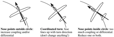
- You can add aileron-rudder coupling (1-4 mixing is set up in PMIX-1, p. 43) for coordinated turns. This setting is highly dependent on the model configuration. Usually only a small amount of rudder is needed, especially if a large amount of differential is present, so start out with 10–15%. Carefully observe the direction of the fuselage relative to the thermal turn the model is making. If the nose points towards the inside of the circle, the coupling is too high, and if it points towards the outside of the circle, you need more coupling. When everything is set properly, the fuselage will be tangent to the thermal turn circle.
Nose points outside circle: increase coupling and/or differential Coordinated turn: fuse lines up with turn direction (don't change anything!) Nose points inside circle: too much coupling or differential. Reduce one or both.
While you are flying, watch for trim changes during launch and butterfly control actions and set the compensations to cancel them out.
You can also add other mixing types such as elevator-to-flap mixing (ELE-FL, p. 48) to make better pylon turns. You may wish to refer to the sailplane trimming chart following. Whatever you do, Enjoy!
Sailplane Trimming Chart
The chart on the next page describes the procedures that may be followed when trimming a new sailplane. The flights for trimming must be made in near-calm conditions, and should be repeated several times before making adjustments.
One of the most critical steps is the center-of-gravity (CG)/decalage testing (Step 3). Decalage is a fancy way of describing the relative positions of the wing and horizontal tail. Although the control neutrals have been set in Step 1, there are differing combinations of elevator trim and CG that produce stable flight. In general, you get better performance by moving the CG aft, but at the same time you reduce the stability and make the model more difficult to fly, or make it so that constant attention is required. Moving the CG aft lessens the download on the model's tail and in some cases produces an upload, which means the wing and tail are working together and not against each other as they do with a forward CG. Many contest flyers use a CG position located between 35 and 40% of the mean wing chord, which is near the aft limits for stability. A nose-heavy model will be easier to fly but will lack the performance of the aft-CG model.
You should also set differential and/or rudder coupling carefully. Incorrect settings will result in needless increased drag, and may be checked fairly easily. If you practice keeping the fuselage straight while gently rocking the wings back and forth, you'll learn how to coordinate turns and won't need coupled rudder any more. You can also learn about the proper amount of differential or rudder coupling by studying the figures of the model circling.
Whatever you do, be sure to spend a lot of time trimming your sailplane. If you have a nearby slope, practice flying on very light days, where you can just barely keep the model airborne. It is under these conditions that you learn if your model is really trimmed properly.
57
SAILPLANE TRIMMING CHART ©1995 by Don Edberg (all rights reserved)
| To test for _ | Test Procedure | Observations | Adjustments |
|---|---|---|---|
| 1. Model Control Neutrals | Fly the model straight and level | Adjust the transmitter trims for hands-off straight & level flight, no camber control. | Change electronic subtrims and/or adjust clevises to center transmitter trims. |
| 2. Control ThrowsNote: be sure all aileron & flap horn pairs have matching angles | Fly the model and apply full deflection of each control in turn. Camber control in neutral (setup 6 & 9). | Check the model’s response to each control input. Set flaps for as much down flap as possible in glide path control (90° is good) <5° reflex needed. | • Aileron & elevator rates: set for desired authority• Rudder: set for max throw• Set flap motions in Steps 4, 5, & 9. |
| 3. Decalage & Center of Gravity (Note: this is an iterative procedure, depends on desired handling characteristics. Aft CG = less stability but better performance) | Trim for level glide. Enter 45° dive (across wind if any). Release controls when model vertical. CAUTION: beware of airspeed & flutter. | A. Does the model continue its dive without pulling out or diving?B. Does the model start to pull out (nose up)?C. Does the model start to tuck in (nose down)? | A. No adjustmentB. Reduce incidence (add down elevator) and/or reduce nose weightC. Increase incidence (add up elevator) or add nose weight) |
| 4. Butterfly Glide Path Control Settings (Part 1)Note: be sure all aileron & flap horn pairs have matching angles. | Fly the model and apply full deflection of glide path control (usually throttle stick). Observe any pitch changes. | A. Nose drops, up elevator required for level flightB. No pitch changeC. Tail drops, down elevator required to maintain level flight | A. Several options:1) more up elevator mixing;2) reduce aileron reflex*;3) increase flap motion*B. No adjustmentC. Reverse of A |
| 4. Butterfly Glide Path Control Settings (Part 2) | Fly the model and apply full glide path control. Observe any roll motion. | A. Model rolls to right when glide path control (throttle stick) activatedB. No roll motionC. Model rolls to left | A. Mix in less right & more left aileron reflex with throttle motionB. No adjustmentC. Reverse of A |
| 5. Differential/Coupled Rudder setting | Fly the model and apply alternating left & right aileron commands. Observe path of fuselage line (p. 51). | A. Model yaws to right with left aileron and vice versaB. Fuselage traces straight lineC. Model yaws to left with left aileron and vice versa | A. Increase differential and/or amount of rudder couplingB. No adjustmentC. Reduce differential and/or amount of rudder coupling |
| 6. Camber (full wing aileron & flap droop or reflex) setting | Put the model in a straight glide passing in front of you. Apply camber control. | A. Model slows down & stalls or sinks rapidlyB. Model slows slightlyC. Model speed unchanged | A. Reduce amount of droopB. No change neededC. Increase droop amount |
| 7. Launch Settings (Part 1) | Switch to Launch mode. Launch the model & observe climb angle and required control inputs | A. Shallow climb angle; lots of up elevator requiredB. Model climbs steeply with little control input neededC. Too steep climb, weaves back & forth, down elevator required | A. Move towhook rearwards small amount, increase up elevator preset a littleB. No adjustmentC. Move towhook forward, increase down elevator preset |
| 8. Launch Settings (Part 2) | Switch to Launch mode. Launch the model & observe climb angle and required control inputs | A. Model banks left on towB. Model climbs straight ahead with no roll input neededC. Model banks right on towD. Model tip stalls to one side | A. Reduce left ail & flap droop or increase right ail & flap droopB. No adjustmentC. Reverse of A aboveD. Be sure droop same on both sides. Increase aileron droop or decrease flap droop (no typo) |
| 9. Speed Settings | Switch to speed mode (entire TE reflexed slightly, no more than □/□□” or 1.5 mm) | A. Nose dropsB. No pitch changeC. Tail drops | A. Increase up elevator presetB. No adjustmentC. Reverse of A |
| 10. Elevator-to-Flap Coupling Setting | Fly model at high speed, bank & pull up | A. Model keeps speedB. Model slows down | A. Increase down flapB. Decrease down flap |
*Note: Swept wing planform may cause opposite reactions, so experiment until proper behavior is attained.
58
BFLY — Butterfly Mixing (“Crow”)
The Butterfly mixing function – sometimes called “crow” – is used for glide path control for landing or for limiting speed when in a dive. Butterfly mixing is controlled with the throttle stick and raises the ailerons and lowers the flaps (two aileron servos are required, using CH1 and CH7, and the same setting applies to both, so horns must be identical). Butterfly will work with either one or two flap servos. All of the servos move linearly with throttle stick motion.
Butterfly mixing can generate a change in pitch, so the elevator may be adjusted to compensate. Sudden changes in pitch can be suppressed by setting the delay ("DLY") item at the elevator: a 100% delay means that the elevator takes about two seconds to go to full travel.
Butterfly mixing is manually turned on and off with Switch A. If you turn on the transmitter, and there’s a beeping sound, it could be your butterfly activation switch is in the ON position.
At the throttle stick “idle” position, butterfly mixing has maximum throws. [If you wish to move the ATL to the high throttle end, turn on the transmitter holding the two MODE buttons down (or the two BASIC or two ADVANCE MENU buttons). You’ll see a display “STICK MODE x.” Press the lower MODE button to get to the “TH-FNC” display. Now press the minus (-) DATA INPUT key to reverse the throttle function. You may need to reverse the signs on some mixers after you perform this operation, which applies to all model memories.]
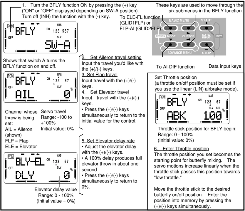
Butterfly mixing programming
- Turn the BFLY function ON by pressing the (+) key ("ON" or "OFF" displayed depending on SW-A position). Turn off (INH) the function with the (-) key.
To ELE-FL function (GLID1FLP) or FLP-AI (GLID2FLP)
These keys are used to move through the six submenus in the BFLY function.
Shows that switch A turns the BFLY function on and off.
-
Set Aileron travel setting Input the travel you'd like with the (+)/(-) keys.
-
Set Flap travel Input travel with the (+)/(-) keys.
-
Set Elevator travel Input travel with the (+)/(-) keys. • Press the (+)/(-) keys simultaneously to return to the initial value for the control.
To AI-DIF function Data input keys
Set Throttle position (a throttle on/off position must be set if you use the linear (LIN) airbrake mode).
Channel whose throw is being set: AIL = Aileron (shown) FLP = Flap ELE = Elevator
Servo travel Range: -100 to +100% Initial value: 0%
Throttle stick position for BFLY begin: Range: 0 - 100% (Initial value: 0%)
- Set Elevator delay rate • Adjust the elevator delay with the (+)/(-) keys. • A 100% delay produces full elevator throw in about one second • Press the (+)/(-) keys simultaneously to return to 0%.
Elevator delay value Range: 0 - 100% (Initial value = 0%)
- Enter Throttle position The throttle position you set becomes the starting point for butterfly mixing. The servo motions increase linearly when the throttle stick passes this position towards "low throttle."
Move the throttle stick to the desired butterfly on/off position. Enter the position into memory by pressing the (+)/(-) keys simultaneously.
59
FLP→Al: Flap→Aileron Mixing
Flap→aileron mixing is used to change the camber (the angle of the ailerons and flaps) over the entire wing, which produces less drag than just dropping the flaps by themselves. When you have Elevator→Flap mixing activated along with Flap→Aileron mixing, the entire trailing edge droops or reflexes with elevator stick motion.
 Flap→aileron mixing
You can program an offset of the flaps as described in step 3 below, but we suggest leaving this at zero initially.
Switch "D" is programmed to turn this function on and off, but you can have the function always on if you like by selecting the NULL direction.
Setting up Flap→Aileron mixing
- Turn the FLP>Al function ON or OFF by pressing the (+) key ("ON" or "OFF" displayed depending on switch D's position). Turn off (INH) the function with the (-) key.
These keys are used to move through the four submenus in the FLP-Al function.
To Al-FLP function
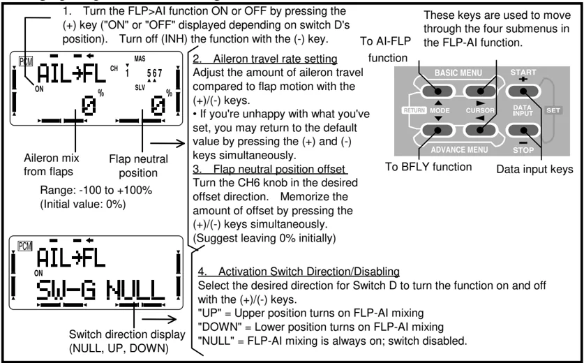
Aileron mix from flaps Range: -100 to +100% (Initial value: 0%)
Flap neutral position
- Aileron travel rate setting Adjust the amount of aileron travel compared to flap motion with the (+)/(-) keys. • If you're unhappy with what you've set, you may return to the default value by pressing the (+) and (-) keys simultaneously.
To BFLY function Data input keys
-
Flap neutral position offset Turn the CH6 knob in the desired offset direction. Memorize the amount of offset by pressing the (+)/(-) keys simultaneously. (Suggest leaving 0% initially)
-
Activation Switch Direction/Disabling Select the desired direction for Switch D to turn the function on and off with the (+)/(-) keys. "UP" = Upper position turns on FLP-Al mixing "DOWN" = Lower position turns on FLP-Al mixing "NULL" = FLP-Al mixing is always on; switch disabled.
Switch direction display (NULL, UP, DOWN)
60
AIL→FL — Aileron→Flap Mixing
Aileron-to-flap mixing is used to improve the roll rate and to reduce the wing’s induced drag during rolls and banking maneuvers by operating the flaps differentially as ailerons. The function may be turned on and off by switch "G", or it may be always on.
 REAR VIEW OF MODEL WITH LEFT AILERON COMMAND
Aileron→flap mixing
For normal flying, a value of about 50% is often used. But for slope racing or F3B models in speed runs, you may wish to use a larger value approaching 100%.
Setting up aileron-to-flap mixing
- Turn the AIL-FL function ON or OFF by pressing the (+) key ("ON" or "OFF" displayed depending on switch G's position). Turn off (INH) the function with the (-) key.
PCM AIL→FL CH 1 MAS 567 ON SLV % % 0 0
Flap travel commanded by Left aileron stick Flap travel commanded by Right aileron stick
Range: -100 to +100% (Initial value: 0%)
These keys are used to move through the three submenus in the AIL-FL function.
To ELE-FL function To FLP-AI function Data input keys
-
Flap travel setting Push the aileron stick in the direction you want to adjust and adjust the flap amount with the (+)/(-) keys. Repeat for other aileron stick position. • If you're unhappy with what you've set, you may return to the default value by pressing the (+) and (-) keys simultaneously.
-
Activation Switch Direction/Disabling Select the desired direction for Switch G to turn the function on and off with the (+)/(-) keys. "UP" = Upper position turns on AIL-FL mixing "DOWN" = Lower position turns on AIL-FL mixing "NULL" = AIL-FL mixing is always on; switch disabled.
PCM AIL→FL ON SW-G NULL
Switch direction display (NULL, UP, DOWN)
61
START — Start (Launch) Presets
The Start function is used to offset the aileron, elevator, and flap servos to the position that provides maximum lift during launch. Normally the ailerons and flaps are drooped about 20-30°, with the flaps drooped slightly more to prevent tip-stalling on tow. The elevator neutral can also be offset in order to trim out any pitch changes caused by the flap and aileron presets. This function is activated by flipping switch G to the aft position.
If you wish to have the three-position switch above the left-hand stick (position E), you should purchase the 8UH system.
 START (launch) presets
Inputting the Start (Launch) presets for your model
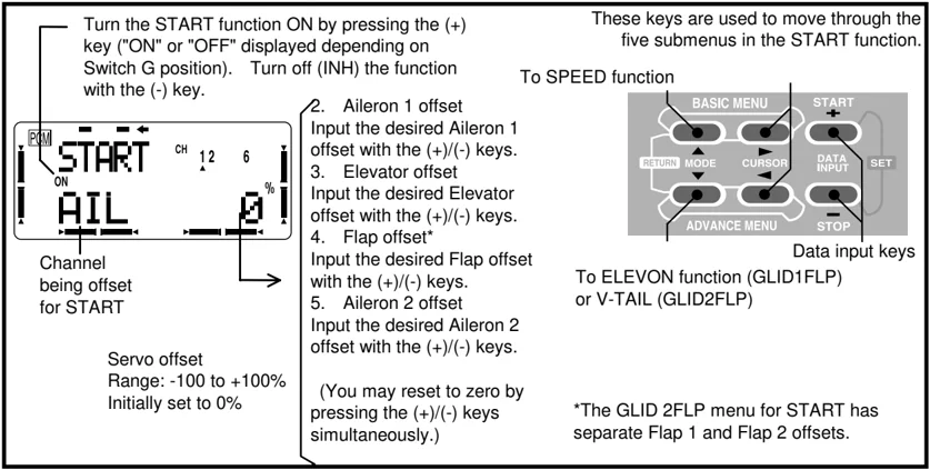
Turn the START function ON by pressing the (+) key ("ON" or "OFF" displayed depending on Switch G position). Turn off (INH) the function with the (-) key.
These keys are used to move through the five submenus in the START function.
To SPEED function
Data input keys
To ELEVON function (GLID1FLP) or V-TAIL (GLID2FLP)
*The GLID 2FLP menu for START has separate Flap 1 and Flap 2 offsets.
Channel being offset for START
Servo offset Range: -100 to +100% Initially set to 0%
- Aileron 1 offset Input the desired Aileron 1 offset with the (+)/(-) keys.
- Elevator offset Input the desired Elevator offset with the (+)/(-) keys.
- Flap offset* Input the desired Flap offset with the (+)/(-) keys.
- Aileron 2 offset Input the desired Aileron 2 offset with the (+)/(-) keys.
(You may reset to zero by pressing the (+)/(-) keys simultaneously.)
62
SPEED — Speed presets
The Speed function is used to offset the aileron, elevator, and flap servos to the position that provides maximum drag for cruise and high-speed flight. Normally the ailerons and flaps are raised about 3-5°. Some airfoils, notably the RG-15, actually have higher drag with reflex, so Speed function should not be used with this section and other similar ones. The elevator neutral can also be offset in order to trim out any pitch changes caused by the trailing edge reflex. This function is activated by flipping switch G to the forward position.
If you wish to have the three-position switch above the left-hand stick (position E), you should purchase the 8UH system.
 Speed presets
Inputting the Speed presets for your model
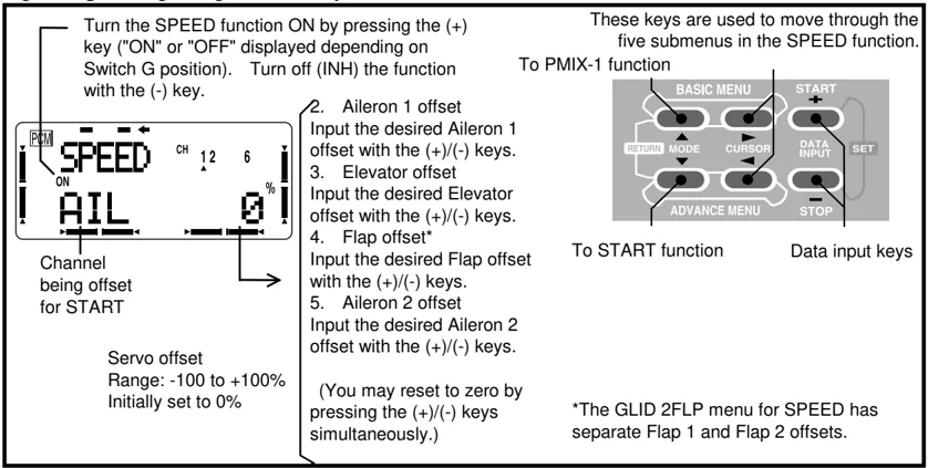
Turn the SPEED function ON by pressing the (+) key ("ON" or "OFF" displayed depending on Switch G position). Turn off (INH) the function with the (-) key.
These keys are used to move through the five submenus in the SPEED function.
To PMIX-1 function
BASIC MENU START RETURN MODE CURSOR DATA INPUT SET ADVANCE MENU STOP
To START function Data input keys
PCM SPEED CH 12 6 ON AIL 0 %
Channel being offset for START
Servo offset Range: -100 to +100% Initially set to 0%
- Aileron 1 offset Input the desired Aileron 1 offset with the (+)/(-) keys.
- Elevator offset Input the desired Elevator offset with the (+)/(-) keys.
- Flap offset* Input the desired Flap offset with the (+)/(-) keys.
- Aileron 2 offset Input the desired Aileron 2 offset with the (+)/(-) keys.
(You may reset to zero by pressing the (+)/(-) keys simultaneously.)
*The GLID 2FLP menu for SPEED has separate Flap 1 and Flap 2 offsets.
63
HELICOPTER BASIC MENU FUNCTIONS
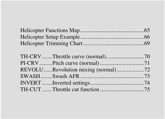
The following section (pages 65 – 75) describes how to use the helicopter-specific Basic Menu functions for helicopters (model types HELISWH1, HELISWH2, HELISWH4, HELISR-3, HELISN-3). The functions of the other Basic Menu items are contained in the aircraft (ACRO) section, pages 26 – 40.
The helicopter Advanced Function section begins on page 77.
-
Helicopter Functions Map ........ 65
-
Helicopter Setup Example ........ 66
-
Helicopter Trimming Chart ........ 69
-
TH-CRV ........ Throttle curve (normal) ........ 70
-
PI-CRV ........ Pitch curve (normal) ........ 71
-
REVOLU ........ Revolution mixing (normal) ........ 72
-
SWASH ........ Swash AFR ........ 73
-
INVERT ........ Inverted settings ........ 74
-
TH-CUT ........ Throttle cut function ........ 75
64
HELICOPTER (HELI) FUNCTIONS
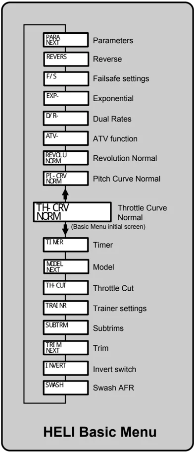
HELI Basic Menu
PARA NEXT Parameters
REVERS Reverse
F/S Failsafe settings
EXP- Exponential
D/R- Dual Rates
ATV- ATV function
REVOLU NCRM Revolution Normal
PI-CRV NCRM Pitch Curve Normal
TH-CRV NCRM Throttle Curve Normal (Basic Menu initial screen)
TIMER Timer
MODEL NEXT Model
TH-CUT Throttle Cut
TRAI NR Trainer settings
SUBTRM Subtrims
TRIM NEXT Trim
INVERT Invert switch
SWASH Swash AFR
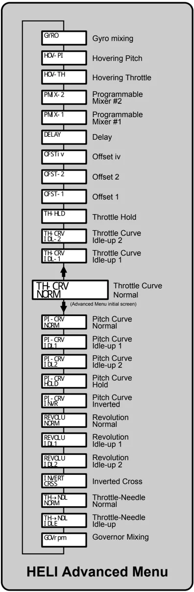
HELI Advanced Menu
GYRO Gyro mixing
HOV- PI Hovering Pitch
HOV-TH Hovering Throttle
PMX-2 Programmable Mixer #2
PMX-1 Programmable Mixer #1
DELAY Delay
OFSTi v Offset iv
OFST-2 Offset 2
OFST-1 Offset 1
TH-HLD Throttle Hold
TH-CRV IDL-2 Throttle Curve Idle-up 2
TH-CRV IDL-1 Throttle Curve Idle-up 1
TH-CRV NCRM Throttle Curve Normal (Advanced Menu initial screen)
PI-CRV NCRM Pitch Curve Normal
PI-CRV IDL-1 Pitch Curve Idle-up 1
PI-CRV IDL2 Pitch Curve Idle-up 2
PI-CRV HOLD Pitch Curve Hold
PI-CRV INVR Pitch Curve Inverted
REVOLU NCRM Revolution Normal
REVOLU IDL-1 Revolution Idle-up 1
REVOLU IDL2 Revolution Idle-up 2
INVERT CRSS Inverted Cross
TH→NDL NCRM Throttle-Needle Normal
TH→NDL IDLE Throttle-Needle Idle-up
GOVrpm Governor Mixing
HELICOPTER SETUP INSTRUCTIONS
The following example shows how the T8U may be programmed for a contest helicopter model. The settings presented here are for a typical model. Your model’s settings are likely to vary from these, but the procedures given will still be applicable.
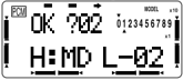
1. Memory Selection
Use the Model menu Select function [MSL] to select a model memory. Choose the Helicopter Setup using the SEL function from Model menu. CAUTION: if you select a new type of model, you’ll loose all the data already in the model memory. This example assumes you’re using model memory 2.
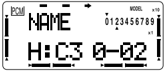
2. Name your model using the Model Name [MNA] function in the model menu.
3. Hook up controls.
In the helicopter, hook up the aileron, elevator, throttle, and rudder servos in accordance with the model’s instructions or plans.
4. Plug Servos Into Receiver.
- CH1 …………………Aileron
- CH2 …………………Elevator
- CH3 …………………Throttle
- CH4 …………………Rudder
- CH5 …………………(spare)
- CH6 …………………Pitch
- CH7 …………………Gyro Sensitivity
- CH8 …………………(spare)
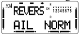
5. Set Servo Throw Direction
Check the proper direction of throw for each servo. Use the Reversing Function [REV] in the Basic menu to set proper throw directions. Reverse channels as necessary to correct throws. Set up the carburetor pushrod so that the carb may be fully closed to shut off the engine.
6. Servo Travel
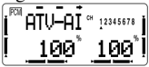
Use the ATV command to limit servo travels to prevent binding.
7. Throttle Cut Setting
After a flight, use the Throttle Cut function to kill your engine with the trainer switch. There is no need to fumble with trim, and the idle trim position will never be lost.
Enter the TH-CUT settings in the Basic menu, and set the desired switch (we recommend using the trainer switch F, in the down or momentary position). Move the throttle stick a few clicks above idle, then press the (+)/(–) keys simultaneously to memorize the position. This makes it so the engine cut function will only operate when the throttle is below the set point, so the engine can’t inadvertently be shut off in flight.
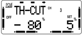
Adjust the throttle servo motion so that when activated, the carburetor is fully closed and there is no binding in the throttle pushrod.
Normal Flight Programs
Continue within the Basic functions menu to set up the Normal flight settings (see the menu structure on p. 65 for more info):
8. Throttle Curve-Normal
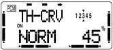
Go to the Throttle Curve [TH-CRV NORM] function. Input the throttle curve to the values shown in the table below:
| Point | 1 | 2 | 3 | 4 | 5 |
|---|---|---|---|---|---|
| Setting (%) | 0 | 25 | 45 | 75 | 100 |
You’ll want to set the throttle so it’s about half open at Point 3. The throttle responds a bit slower than linear near center, and then the response rate approaches linear at both ends.
9. Pitch Curve Normal
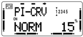
Move to the pitch curve function [PI-CRV NORM] from the model menu. For a semi-symmetrical rotor blade with no twist, the pitch angle should vary from -4° to +12°. We recommend setting the hovering pitch to +4.5°.
Move the hovering pitch knob (CH6) and the hovering throttle knob (CH7) to the center
66
positions (if these functions are activated in the Advance Menu, the knobs may be moved in flight to make adjustments). Next, input pitch curve data so that the normal pitch used in hovering varies between -2.5° and +10°.
The pitch angle should be set so that the high throttle pitch rate is large. This provides high collective sensitivity to help cope with windy conditions.
The following values are recommended starting points for the pitch curve:
10. Revolution Mix Setting
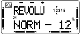
Revolution mixing uses the tail rotor to suppress the torque reaction of the main rotor due to changes in collective pitch. Call up the REVOLU NORM Menu. Input the values as follows:
FLIGHT CONDITION SWITCHING
Your system is already programmed to have settings for Idle-up 1 [IDL1], Idle-up 2 [IDL2], and Throttle Hold [HOLD] in addition to the normal flight condition [NORM]. The menus for these added flight conditions are contained in the Advance Menus. Refer to the menu structure on p. 65 for more info.
The position and ON direction of each flight condition call switch are set as follows:
• Normal [NORM] – for hovering. Operation when all switches OFF.
• Idle-up 1 [IDL1] – for 540° stall turns, looping, rolling stall turns. ON at Switch G center position
• Idle-up 2 [IDL2] – for rolling aerobatics. ON at Switch G forward position.
• Throttle Hold [HOLD] – for autorotation. ON at Switch E forward position.
We recommend that you fly the model and adjust trims and control responses to your liking in hover before setting up another flight condition.
To set the condition data for each flight condition, be sure that you call the appropriate condition by turning on the correct switch (as given above). Double-check to be sure that you are setting the menu you desire.
As mixes are switched on or off, HOLD has highest priority, followed by IDL2, IDL1, and NORM.
I dle-Up 1 Settings
The settings for IDL1 conditions are among those contained in the Advance menus (see the menu structure on p. 65 for more info).
- Throttle Curve Setting: move to the TH-CRV IDL1 menu and activate it. Change the Idle-up 1 throttle curve points to the values shown below:
- Pitch Curve Setting. Move to the PI-CRV IDL1 menu and activate. The Idle-up 1 pitch curve should use the same curve as the normal condition except with the maximum high throttle pitch angle between 8° to 10°, depending on the engine used.
- Idle-up 1 Revolution Setting:
These settings are used in 540° stall turns, looping, and rolling stall turns and are set to be straight ahead when the model is pointing directly into or away from the wind. Move to the REVOLU IDL1 menu and input the following values:
I dle-Up 2 Settings
The settings for IDL2 conditions are also among those contained in the Advance menus (see the menu structure on p. 65).
- Throttle Curve Setting: move to the TH-CRV IDL2 menu and activate with the (+) key. Input the trial throttle curve points as shown below:
| Point | 1 | 2 | 3 | 4 | 5 |
|---|---|---|---|---|---|
| Setting (%) | 60 | 60 | 60 | 75 | 100 |
- Pitch Curve Setting. Step through the menu to the PI-CRV IDL2 menu. Set the pitch curve as follows:
| Point | 1 | 2 | 3 | 4 | 5 |
|---|---|---|---|---|---|
| Setting (%) | 5 | 25 | 50 | 65 | 80 |
| Blade pitch | -3° | +4.5° | +8° |
- Idle-up 2 Revolution Setting: These settings are used in rolls. Move to the REVOLU IDL2 menu and try out the following values for the rudder mixing curve:
| Point | 1 | 2 | 3 | 4 | 5 |
|---|---|---|---|---|---|
| Setting (%) | -20 | -10 | 0 | +10 | +20 |
Throttle Hold Settings
The settings for HOLD conditions, to be used for Autorotation, are also among those contained in the Advance menus (see the menu structure on p. 65).
- Revolution Throttle Hold Setting: TH-HLD sets throttle position near idle and keeps the model pointed straight ahead during autorotation. Move to the Throttle Hold menu and activate by pressing the (+) key, then set switch G to the forward position. Set the hold position (HLDP) maintain engine idling.
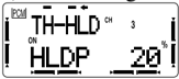
Next, move to the rudder offset setting and set OFST to keep the tail rotor pitch angle to nearly 0°, since there is no torque. Your numerical value may vary from those shown.
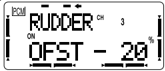
- Pitch Curve Setting. Move to the PI-CRV HOLD menu and activate. During autorotation, high pitch is used at both the HIGH and LOW sides, so set the HIGH and LOW rates to their maximum values: 0 and 100% respectively.
| Point | 1 | 2 | 3 | 4 | 5 |
|---|---|---|---|---|---|
| Setting (%) | 0 | 25 | 50 | 65 | 100 |
| Blade pitch | -4° | +4.5° | +12° |
- Rudder→Throttle Mix Setting Rudder→Throttle mixing is useful for hovering eight, nose-in circle, Top Hat, Pirouette, and other aerobatics. It is normally set up so that rotor speed is maintained to keep altitude constant when the rudder stick is operated at half-throttle.
For helis with normal rotor rotation, commanding right rudder should increase throttle slightly, while using left rudder should decrease throttle slightly.
To set this feature, use one of the PMIX mixers. Press the (+) button to activate it, and set master = Rudder, slave = Throttle. Input the value for left at -10%, and the right value to +10%. Adjust values to suit.
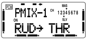
Another use for a programmable mixer The main rotor’s RPM can decrease due to increased loads whenever full cyclic control is used, like when doing a roll. To help keep the RPM up, you can use a mixer with Master = AIL, Slave = THR. About 10% mixing is a good starting point for both directions.
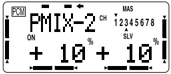
- Trim Offset Setting The Trim Offset menus may be adjusted for Idle-up 1 and Idle-up 2. Aileron, elevator, and rudder trims may be offset to different positions so that the model flies straight ahead during normal flight.
If you find you need some trim offsets in IDL1 or IDL2, call up whichever of the OFST-1 or OFST-2 menus you need. Recommended settings for aileron and elevator offsets are small, from 6% to 10% or as needed.
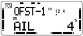
Rudder offset is set by the Revolution Throttle Hold function set previously, so is not included in this menu.
- Delay Settings Delay settings are used to prevent sudden trim changes due to different settings in different flight conditions. You can set different delays
68
for aileron, elevator, and rudder. The delays you set apply to all flight conditions. We recommend trying very small values for the initial settings, say 5 - 10%. A 25% delay is about a half-second transit time between neutral settings.
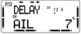
You may use the Hovering Pitch and Hovering Throttle functions for fine trimming changes due to humidity, etc.
This concludes the example setup procedure for helicopters. Be sure to browse through the pages following this example to see what other menus are available for helicopters, such as Hovering Throttle and Pitch knobs, OFST, ACC, DELAY, and INVERT CROSS. You may use a mixer to adjust gyro sensitivity, or to enhance flight capabilities or to correct a response you don't like. Again, we recommend you set up and trim in the Normal flight condition before setting up the alternate flight modes.
Helicopter Flight Trimming Chart
This procedure assumes helicopter is trimmed for hovering. Trimming must be done in near-calm conditions. Repeat tests several times before making adjustments. If any changes are made, go back over the previous steps and verify, or further adjust as necessary.
| To test _ | Test Procedure | Observations | Adjustments |
|---|---|---|---|
| 1. Revo mixing — Up settings (Part 1) | Fly the model straight and level into the wind at 100 ft altitude, lower pitch to 0° | Observe rotation as copter descendsA. No rotationB. Model rotates counterclockwiseC. Model rotates clockwise | A. NoneB. Add right rudder trimC. Add left rudder trim |
| 2. Revo mixing — Up settings (Part 2) | Bring the copter into hover, add full pitch and ascend 75 ft | Observe rotation as copter ascendsA. No rotationB. Model rotates counterclockwiseC. Model rotates clockwise | A. NoneB. Increase UP revo mixC. Decrease UP revo mix |
| 3. Revo Down mixing settings | Begin Down Revo mixing with same number as UP mix. From inverted flight (top of loop, or mid-point of roll, or inverted part of split-S), add full negative pitch | Observe rotation as copter ascendsA. No rotationB. Model rotates clockwiseC. Model rotates counterclockwise | A. No adjustmentB. Increase Down revo mixC. Decrease Down revo mix |
69
TH-CRV — Throttle Curve (Normal)
The throttle curve normal function is used to input the normal (NORM) throttle curve, which is usually not a linear response to throttle stick motion. The normal throttle curve is the basic throttle curve intended for flight around hover. Together with the pitch curve (normal), the throttle curve is adjusted for best climb at a fixed engine RPM. You can program a 5-point throttle curve to get the best engine response relative to throttle stick motion. Each point of the curve can be adjusted over a range of 0% to 100%.
There are three throttle curves in your transmitter: normal (NORM), idle-up 1 (IDL1), and idle-up 2 (IDL2), but only the basic normal throttle curve is displayed in the Basic Menu. The normal curve can be seen and programmed in either the Basic or Advance Menus, but the others are only accessible in the Advance menu.
Setting the Normal throttle curve
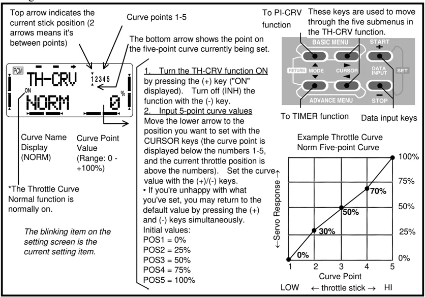
Top arrow indicates the current stick position (2 arrows means it's between points)
Curve points 1-5
The bottom arrow shows the point on the five-point curve currently being set.
To PI-CRV function These keys are used to move through the five submenus in the TH-CRV function.
BASIC MENU START RETURN MODE CURSOR DATA INPUT SET ADVANCE MENU STOP
To TIMER function Data input keys
Curve Name Display (NORM) Curve Point Value (Range: 0 - +100%)
*The Throttle Curve Normal function is normally on.
The blinking item on the setting screen is the current setting item.
- Turn the TH-CRV function ON by pressing the (+) key ("ON" displayed). Turn off (INH) the function with the (-) key.
- Input 5-point curve values Move the lower arrow to the position you want to set with the CURSOR keys (the curve point is displayed below the numbers 1-5, and the current throttle position is above the numbers). Set the curve value with the (+)/(-) keys. • If you're unhappy with what you've set, you may return to the default value by pressing the (+) and (-) keys simultaneously. Initial values: POS1 = 0% POS2 = 25% POS3 = 50% POS4 = 75% POS5 = 100%
Example Throttle Curve Norm Five-point Curve
← Servo Response 100% 75% 70% 50% 50% 25% 30% 0% 0% 1 2 3 4 5 Curve Point LOW ← throttle stick → HI
70
PI-CRV — Pitch Curve (Normal)
The Normal pitch curve function contained in the Basic Menu sets the normal (NORM) curve. The Normal pitch curve is the basic pitch curve for flight near hover. Together with the normal throttle curve, the normal pitch curve is adjusted for best vertical performance at a constant engine speed. You can program the response over a 5-point curve so that you may choose the best rotor pitch angle relative to throttle stick movement. Each of the five points can be adjusted over a 0% to 100% range.
The T8U system helicopter programs contain five pitch curves: normal, idle-up 1 (IDL1), idle-up 2 (IDL2), hold (HOLD), and inverted (INVR). The basic normal pitch curve is the only one displayed in the Basic Menu, but all of the pitch curves can be viewed in the Advance menu. The Normal curve is the same in both the Advance and Basic Menus.
Setting the Normal Pitch Curve
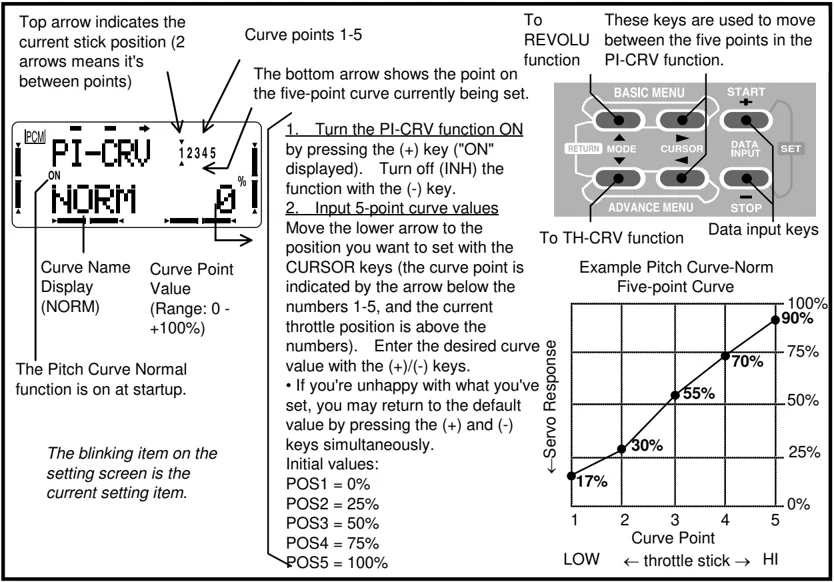
Top arrow indicates the current stick position (2 arrows means it's between points)
Curve points 1-5
The bottom arrow shows the point on the five-point curve currently being set.
To REVOLU function These keys are used to move between the five points in the PI-CRV function.
- Turn the PI-CRV function ON by pressing the (+) key ("ON" displayed). Turn off (INH) the function with the (-) key.
- Input 5-point curve values Move the lower arrow to the position you want to set with the CURSOR keys (the curve point is indicated by the arrow below the numbers 1-5, and the current throttle position is above the numbers). Enter the desired curve value with the (+)/(-) keys. • If you're unhappy with what you've set, you may return to the default value by pressing the (+) and (-) keys simultaneously. Initial values: POS1 = 0% POS2 = 25% POS3 = 50% POS4 = 75% POS5 = 100%
To TH-CRV function Data input keys
Example Pitch Curve-Norm Five-point Curve
Curve Name Display (NORM) Curve Point Value (Range: 0 - +100%)
The Pitch Curve Normal function is on at startup.
The blinking item on the setting screen is the current setting item.
71