AIRCRAFT SETUP INSTRUCTIONS (GENERAL 120 CLASS STUNT PLANE)
The aircraft setup procedure presented below uses a F3A-class model as an example. You may use a similar procedure to set up your own model, but your setting’s numbers and percentages will probably be different.
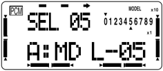
- Enter the Model Select menu (MODEL) by pressing the two BASIC keys, then pressing one of the MODE keys until “MODEL” appears. Press the right (>) CURSOR key to get to the model select function (SEL) and choose a vacant model memory with the plus (+) and minus (-) keys. Select it by pressing both the DATA INPUT keys at once. The following instructions refer to memory #5.
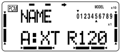
- Press the right (>) CURSOR key twice to get to the model name function (NAME, p. 37). Use the CURSOR and DATA INPUT keys to spell out the name that you wish to appear on the screen, one letter at a time.
- Enter the Parameter (PARA, p. 31) menu by pressing the down MODE key twice. Use the left (<) CURSOR key to select the model type (TYP) function and verify that ACRO (aircraft) is selected. (If it isn’t, select ACRO by pressing the plus or minus DATA INPUT keys until it appears, then pressing both DATA INPUT keys to select it.)
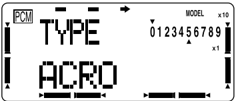
WARNING: selecting a different model type will erase the settings in the model memory. BE SURE you’re in the correct model memory before selecting a new model type.
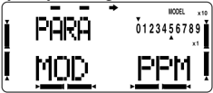
If necessary, go to the modulation (MOD, p. 34) menu to select the proper mode of transmission (F is for FM/PPM transmission, and C is for PCM). This should be set to match your receiver. If you make a change, it won’t take effect until you cycle the power off and on again.
- Next, turn on the Flaperon function (FLPRON, p. 45) in the Advance Menu. To do this, press both ADVANCE buttons simultaneously, then press the MODE button until “FLPRON” appears in the display. Activate by pressing the plus (+) DATA INPUT key (“ON” should appear flashing in the display.
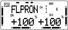
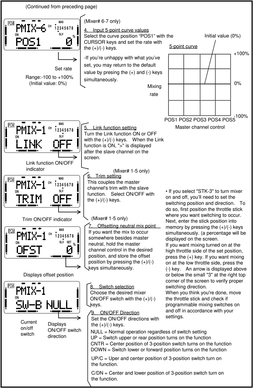
Connect the right aileron servo to receiver CH1 and the left aileron servo to receiver CH6.
Note that you can get differential by adjusting the up and down motion of the two servos in the FLPRON menu. If you don’t need the flap effect, you can use the AI-DIFF menu (and plug the servo into the receiver CH7 output.
-
Check that each servo moves the proper direction. The aileron servos should move in opposite directions for aileron stick motion, and the same direction for flap control. If not, use the Reversing function (REVERS, p. 30) in the Basic Menu to set the proper throw directions for each servo. Also check elevator, rudder, throttle, gear, and any other servos.
-
Set the basic travels with the ATV function in the Basic Menu (ATV, p. 26).
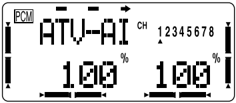
Aileron settings: the left and right aileron travel should be limited to roughly 9/16" (14-15 mm). If necessary, adjust CH1 and CH6 with the ATV function. Choose a location on the servo arm so that the throw is adjusted in the 90-100% range.
Elevator setting: adjust the elevator travel to roughly 9/16" (15 mm) with the ATV function.
Rudder setting: adjust the rudder travel to roughly 45 degrees in the left and right directions with the ATV function.
- Dual Rate setting (D/R, p. 26) Adjust the servo motions with the D/R function (in the Basic menu).
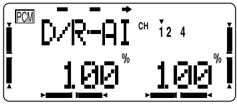
Aileron Dual Rates: adjust the aileron travel to roughly 7/16" (11 mm). You may also wish to adjust EXP so that its rate is -20 to -30% to soften things around neutral.
Elevator D/R: adjust the up side to 15/32" (12 mm) and the down side to 17/32" (13 mm). EXP should be -15 to -20%.
Rudder: adjust the left and right travel to 40 to 45 degrees. EXP should be about -20%.
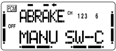
- Airbrake (ABRAKE, Advance menu, p. 47): an airbrake effect is obtained by raising both ailerons and adding elevator to trim. This high-drag configuration assists landings in small airfields. It is possible to loose some aileron effectiveness so test the airbrake effect at altitude before trying it on a landing approach. You should spend some time fine adjusting the elevator travel so that there is no trim change with the application of airbrakes.
The rates may vary considerably for different models, but for initial settings choose the flap rate to be (+)50-55% for both CH1 and CH6. The ELE rate should be set to -7% --10%.
We recommend that you select the Manual mode. The default airbrake switch is SW(C), lower position ON. Move SW(C) to the lower position and verify its operation.
- Snap Roll (SNP, p. 50, Advance Menu) Activate the Snap Roll function by pressing the plus (+) DATA INPUT key.
Set the deflection rate for each switch position. Be sure that the direction of motion of each control is correct.
Aileron: 80 - 100%
Elevator: 90 - 110%
Rudder: 60 - 70%
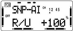
We recommend that you activate the safety switch. This stops your model from snap rolling if the landing gear are not retracted, so you don't accidentally snap while taking off or landing.
If your aircraft snaps poorly, increase the deflection of the elevator and rudder. Note that some models don't snap even when the control deflections are increased. This may caused by too far forward center of gravity, or by the characteristics of the airplane.
- Failsafe settings: we recommend that you set the Fail Safe function (F/S, p. 29) to move the throttle to idle if interference is experienced. Note that the failsafe function only operates in the PCM transmission mode.
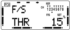
- Now take advantage of your system's other great programming capabilities. You may set such functions as Throttle→Needle and Throttle delay to improve engine response, and couple elevator to flaps for tighter corners in the elevator-to-flap mixer (ELE→FL, p. 48). You may want to use programmable mixers to get rid of unwanted tendencies (for example, pitching up during knife-edge flight. Finally, if you have dual elevator servos, you can turn on the Ailevator function (ALVATR, p. 49) to increase roll authority in low-speed maneuvers. The sky's the limit — enjoy!
Pattern Aircraft Flight Trimming Chart
The following chart may be used to systematically set up and trim a model for straight flight and aerobatic maneuvers. Please note that for best results, trimming should be done in near-calm conditions. Before you decide to make a change, be sure to try the test several times before making adjustments. If any changes are made, go back through the previous steps and verify that they are not also affected. If they are, make further adjustments as necessary.
| To test for _ | Test Procedure | Observations | Adjustments |
|---|---|---|---|
| 1. Control neutrals | Fly the model straight and level | Use the transmitter trims for hands-off straight & level flight. | Change electronic subtrims or adjust clevises to center transmitter trims. |
| 2. Control throws | Fly the model and apply full deflection of each control in turn | Check the response of each control• Aileron high-rate: 3 rolls in 4 seconds; low-rate: 3 rolls/6 sec• Elevator high-rate: to give a smooth square corner; low-rate gives approx. 130 ft diameter loop• Rudder: high-rate 30-35° for stall turns; low rate maintains knife-edge | Change ATV (for high rates), and Dual Rate settings (for low rates) to achieve desired responses. |
| 3. Decalage | Power off vertical dive (crosswind if any). Release controls when model vertical (elevator trim must be neutral) | A. Model continues straight downB. Model starts to pull out (nose up)?C. Model starts to tuck in (nose down)? | A. No adjustmentB. Reduce incidenceC. Increase incidence |
| 4. Center of Gravity | Method 1: Roll into near vertically-banked turn.Method 2: Roll model inverted | A1. Nose dropsB1. Tail dropsA2. Lots of forward stick (down elevator) required to maintain level flightB2. No forward stick (down elevator) required to maintain level flight, or model climbs | A. Add weight to tailB. Add weight to nose |
| 5. Tip weight (coarse adjustment) | Fly model straight & level upright. Check aileron trim maintains level wings. Roll model inverted, wings level. Release aileron stick. | A. Model does not drop a wing.B. Left wing drops.C. Right wing drops. | A. No adjustmentB. Add weight to right tip.C. Add weight to left tip. |
| 6. Side Thrust & Warped Wing | Fly model away from you into any wind. Pull it into a vertical climb, watch for deviations as it slows down. | A. Model continues straight up.B. Model veers leftC. Model veers rightD. Model rolls right | A. No adjustmentB. Add right thrustC. Reduce right thrustD. Put trim tab under left wing tip * |
| 7. Up/Down Thrust | Fly the model on normal path into any wind, parallel to strip, at a distance of around 100 meters from you (elevator trim should be neutral as per Test 3). Pull it into a vertical climb & neutralize elevator | A. Model continues straight upB. Model pitches up (goes toward top of model)C. Model pitches down (goes toward bottom of model) | A. No adjustmentB. Add down thrustC. Reduce down thrust |
| 8. Tip weight (fine adjustment) | Method 1: fly the model as per Test 6 and pull into a reasonably small diameter loop (one loop only)Method 2: fly the model as per Test 6 and then push into an outside loop (one only, fairly tight) | A. Model comes out with wings levelB. Model comes out right wing lowC. Model comes out left wing low | A. No adjustment necessaryB. Add weight to left tipC. Add weight to right tip |
24
Pattern Aircraft Flight Trimming Chart (continued)
| To test for _ | Test Procedure | Observations | Adjustments |
|---|---|---|---|
| 9. Aileron differential | Method 1: fly model toward you & pull into a vertical climb before it reaches you. Neutralize controls, then half-roll the model. | A. No heading changesB. Heading change opposite to roll command (i.e. heading veers left after right roll)C. Heading change in direction of roll command | A. Differential settings OKB. Increase differentialC. Decrease differential |
| Method 2: fly model on normal pass and do three or more rolls | A. Roll axis on model centerlineB. Roll axis off to same side of model as roll command (i.e. right roll, roll axis off right wing tip)C. Roll axis off to opposite side of model as roll command | A. Differential settings OKB. Increase differentialC. Decrease differential | |
| Method 3: fly the model straight and level and gently rock the aileron stick back and forth | A. Model flies straight ahead without yawingB. Model yaws away from roll command (i.e. right roll, yaw left)C. Model yaws towards roll command (i.e. right roll, yaw right) | A. Differential settings OKB. Increase differentialC. Decrease differential | |
| 10. Dihedral | Method 1: Fly the model on normal pass and roll into knife-edge flight; maintain flight with top rudder (do this test in both left & right knife-edge flight)Method 2: Apply rudder in level flight | A. Model has no tendency to rollB. Model rolls in direction of applied rudderC. Model rolls in opposite direction in both tests | A. Dihedral OKB1. Reduce dihedralB2. Use mixer to produce aileron opposing rudder travel (start with 10%)C1. Increase dihedralC2. Mix ailerons with rudder direction 10% |
| 11. Elevator alignment (for models with independent elevator halves) | Fly the model as in Test 6 and pull up into an inside loop. Roll it inverted and repeat the above by pushing it up into an outside loop. | A. No rolling tendency when elevator appliedB. Model rolls in same direction in both tests — halves misaligned.C. Model rolls opposite directions in both tests. One elevator half has more throw than the other (model rolls to side with most throw). | A. Elevators in correct alignmentB. Either raise one half, or lower the otherC. Reduce throw on one side, or increase throw on the other. |
| 12. Pitching in knife-edge flight | Fly the model as in Test 10 | A. There is no pitch up or downB. The nose pitches up (the model climbs laterally)C. Nose pitches down (model dives laterally) | A. No adjustment neededB. Alternate cures:1) move CG aft;2) increase incidence;3) droop ailerons;4) mix down elevator with rudderC. Reverse ‘B’ above |
*Trim tab is □/□□” x □/□” x 4” trailing edge stock, placed just in front of aileron on bottom, pointed end forward.
25
ATV — Adjustable Travel Volume
The ATV function is used to set the travel of each servo in both directions. At a 100% setting, the throw of the servo is approximately 40° for channels 1 – 4 and approximately 55° for channels 5 – 8. Reducing the percentage settings reduces the total servo throw in that direction. The ATV menus should be set to prevent any servo binding at extreme travel.
Setting ATV on your system:
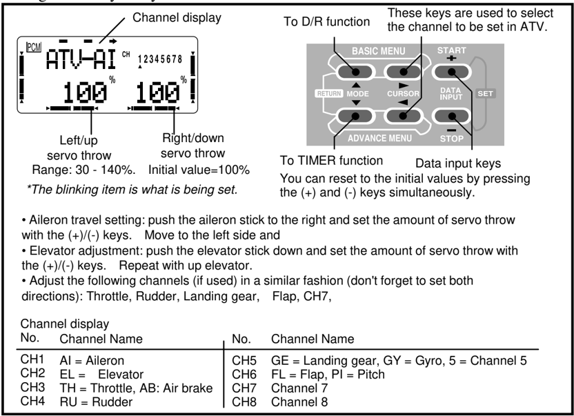
Channel display To D/R function These keys are used to select the channel to be set in ATV.
Left/up servo throw Range: 30 - 140%.
Right/down servo throw Initial value=100%
The blinking item is what is being set.
To TIMER function Data input keys You can reset to the initial values by pressing the (+) and (-) keys simultaneously.
• Aileron travel setting: push the aileron stick to the right and set the amount of servo throw with the (+)/(-) keys. Move to the left side and • Elevator adjustment: push the elevator stick down and set the amount of servo throw with the (+)/(-) keys. Repeat with up elevator. • Adjust the following channels (if used) in a similar fashion (don't forget to set both directions): Throttle, Rudder, Landing gear, Flap, CH7,
Channel display No. Channel Name No. Channel Name CH1 AI = Aileron CH5 GE = Landing gear, GY = Gyro, 5 = Channel 5 CH2 EL = Elevator CH6 FL = Flap, PI = Pitch CH3 TH = Throttle, AB: Air brake CH7 Channel 7 CH4 RU = Rudder CH8 Channel 8
D/R — Dual Rates
You can use D/R dual rate settings to reduce (or increase) the servo travels by flipping a switch, or they can be engaged by any stick position. The travel reduction or increase for the ailerons, elevator, and rudder may be controlled by this menu.
The default locations of the Dual rate switches (factory settings) are as follows: aileron: Switch D; elevator: Switch A; rudder: Switch B.
You may select your own positions for the switches. You may also program your system so that the dual rates are automatically activated when you move any stick past a certain position.
26
Setting Dual Rate Values and Switches
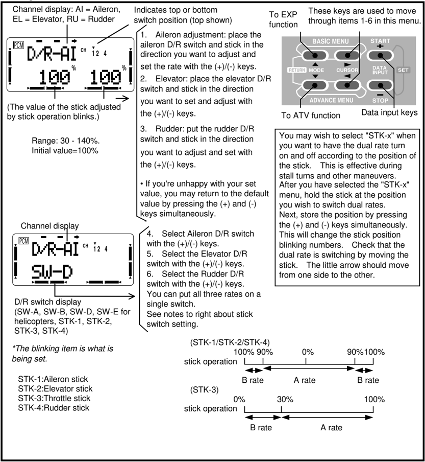
Channel display: AI = Aileron, EL = Elevator, RU = Rudder
Indicates top or bottom switch position (top shown)
To EXP function These keys are used to move through items 1-6 in this menu.
To ATV function Data input keys
(The value of the stick adjusted by stick operation blinks.)
Range: 30 - 140%. Initial value=100%
- Aileron adjustment: place the aileron D/R switch and stick in the direction you want to adjust and set the rate with the (+)/(-) keys.
- Elevator: place the elevator D/R switch and stick in the direction you want to set and adjust with the (+)/(-) keys.
- Rudder: put the rudder D/R switch and stick in the direction you want to adjust and set with the (+)/(-) keys.
- If you're unhappy with your set value, you may return to the default value by pressing the (+) and (-) keys simultaneously.
You may wish to select "STK-x" when you want to have the dual rate turn on and off according to the position of the stick. This is effective during stall turns and other maneuvers. After you have selected the "STK-x" menu, hold the stick at the position you wish to switch dual rates. Next, store the position by pressing the (+) and (-) keys simultaneously. This will change the stick position blinking numbers. Check that the dual rate is switching by moving the stick. The little arrow should move from one side to the other.
Channel display
D/R switch display (SW-A, SW-B, SW-D, SW-E for helicopters, STK-1, STK-2, STK-3, STK-4)
The blinking item is what is being set.
STK-1:Aileron stick STK-2:Elevator stick STK-3:Throttle stick STK-4:Rudder stick
- Select Aileron D/R switch with the (+)/(-) keys.
- Select the Elevator D/R switch with the (+)/(-) keys.
- Select the Rudder D/R switch with the (+)/(-) keys. You can put all three rates on a single switch. See notes to right about stick switch setting.
(STK-1/STK-2/STK-4) stick operation 100% 90% 0% 90% 100% B rate A rate B rate
(STK-3) stick operation 0% 30% 100% B rate A rate
27
EXP — Exponential Settings
Exponential settings may be used to change the response curve of the servos to make flying more pleasant. You can make the servo movement less or more sensitive around neutral for aileron, elevator, throttle, and rudder. It can also be set for each side of the dual rate switches. Negative exponential (–) makes the servo movement around the stick neutral less sensitive and positive (+) makes the servo movement more sensitive.
For throttle, exponential is applied from the end of travel rather than for neutral like the other controls. When the "–" side is increased, the idle sensitivity decreases and the high throttle sensitivity increases. This is best understood by experimenting with a servo.
Setting Exponential Values
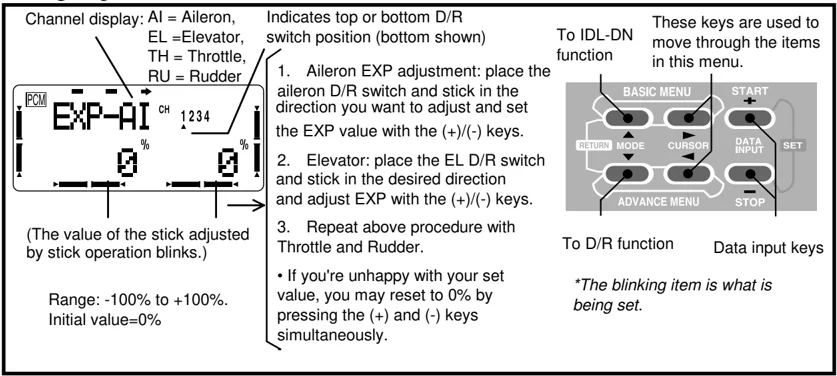
Channel display: AI = Aileron, EL =Elevator, TH = Throttle, RU = Rudder
Indicates top or bottom D/R switch position (bottom shown)
To IDL-DN function
These keys are used to move through the items in this menu.
-
Aileron EXP adjustment: place the aileron D/R switch and stick in the direction you want to adjust and set the EXP value with the (+)/(-) keys.
-
Elevator: place the EL D/R switch and stick in the desired direction and adjust EXP with the (+)/(-) keys.
-
Repeat above procedure with Throttle and Rudder.
• If you're unhappy with your set value, you may reset to 0% by pressing the (+) and (-) keys simultaneously.
To D/R function
Data input keys
(The value of the stick adjusted by stick operation blinks.)
Range: -100% to +100%. Initial value=0%
The blinking item is what is being set.
28
IDL-DN — Idle Down Function
The Idle Down function lowers the engine idling speed when either the airbrake switch (SW C) or landing gear switch (SW G) is activated. This function may be used whenever you wish to raise the engine idling speed to prevent the engine from stalling, and to lower the engine idling speed for landing.
Setting the IDL-DN function
- Activate the IDL-DN by pressing the (+) key ("ON" or "OFF" will be displayed). You may turn off the function by pressing the (-) key (INH will be displayed).
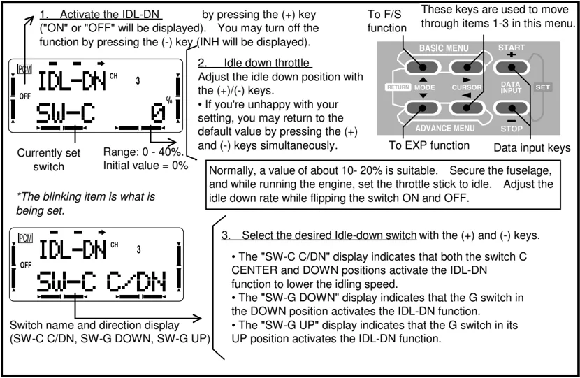
Currently set switch The blinking item is what is being set.
Range: 0 - 40%. Initial value = 0%
Switch name and direction display (SW-C C/DN, SW-G DOWN, SW-G UP)
- Idle down throttle. Adjust the idle down position with the (+)/(-) keys. • If you're unhappy with your setting, you may return to the default value by pressing the (+) and (-) keys simultaneously.
To F/S function These keys are used to move through items 1-3 in this menu. To EXP function Data input keys
Normally, a value of about 10- 20% is suitable. Secure the fuselage, and while running the engine, set the throttle stick to idle. Adjust the idle down rate while flipping the switch ON and OFF.
- Select the desired Idle-down switch with the (+) and (-) keys. • The "SW-C C/DN" display indicates that both the switch C CENTER and DOWN positions activate the IDL-DN function to lower the idling speed. • The "SW-G DOWN" display indicates that the G switch in the DOWN position activates the IDL-DN function. • The "SW-G UP" display indicates that the G switch in its UP position activates the IDL-DN function.
F/S — Fail Safe Function (PCM mode only)
The Fail Safe function is used to prescribe what the PCM receiver will do in the event radio interference is received. In this menu, you may select from one of two options of operation for each channel. The "NORM" (normal) setting holds the servo in its last commanded position, while the "F/S" (Fail Safe) function moves each servo to a predetermined position. The default setting is NORM (normal) for all channels.
The use of the fail safe function is recommended from the standpoint of safety. You may wish to set the throttle channel so that the engine idles when there's interference. This may give enough time to fly away from and recover from the radio interference. If you choose to specify a failsafe setting, the fail safe data are automatically transmitted once each minute.
Battery Failsafe
Your system provides a second safety function called Battery Failsafe. When the airborne battery voltage drops below approximately 3.8V, the battery fail safe function moves the throttle to a predetermined position.
When the battery failsafe function is activated, your engine will move to idle (if you haven't set a position) or a preset position. You should immediately land. You may temporarily reset the failsafe function by moving the throttle stick to idle, at which time you'll have about 30 seconds of throttle control before the battery function reactivates.
29
30
Setting the Failsafe Function
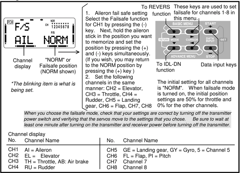
The blinking item is what is being set.
- Aileron fail safe setting
Select the Failsafe function for CH1 by pressing the (-) key. Next, hold the aileron stick in the position you want to memorize and set the position by pressing the (+) and (-) keys simultaneously. (If you wish, you may return to the NORM position by pressing the (+) key) - Set the following channels in the same manner: CH2 = Elevator, CH3 = Throttle, CH4 = Rudder, CH5 = Landing gear, CH6 = Flap, CH7, CH8
To REVERS function
These keys are used to set failsafe for channels 1-8 in this menu.
To IDL-DN function
Data input keys
The initial setting for all channels is "NORM". When failsafe mode is turned on, the initial position settings are 50% for throttle and 0% for the other channels.
When you choose the failsafe mode, check that your settings are correct by turning off the transmitter power switch and verifying that the servos move to the settings that you chose. Be sure to wait at least one minute after turning on the transmitter and receiver power before turning off the transmitter.
Channel display
| No. | Channel Name | No. | Channel Name |
|---|---|---|---|
| CH1 | AI = Aileron | CH5 | GE = Landing gear, GY = Gyro, 5 = Channel 5 |
| CH2 | EL = Elevator | CH6 | FL = Flap, PI = Pitch |
| CH3 | TH = Throttle, AB: Air brake | CH7 | Channel 7 |
| CH4 | RU = Rudder | CH8 | Channel 8 |
REVERS — Servo Reversing
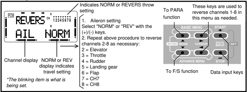
The servo reverse function may be used when you need to change the direction that a servo responds to a control stick motion. When you use this function, BE SURE THAT YOUR CONTROL IS MOVING THE CORRECT DIRECTION. If you are using Advance Menu functions, set correct travels in the REVERS menu first, before setting up the Advance Menu.
Reversing Servos
The blinking item is what is being set.
- Aileron setting
Select "NORM" or "REV" with the (+)/(-) keys. - Repeat above procedure to reverse channels 2-8 as necessary:
2 = Elevator
3 = Throttle
4 = Rudder
5 = Landing gear
6 = Flap
7 = CH7
8 = CH8
To PARA function
These keys are used to reverse channels 1-8 in this menu as needed.
To F/S function
Data input keys
30
PARA — Parameter Menus
The parameter function includes a number of submenus that are used to input basic model data settings. This is best understood by viewing the menu structure on p. 16.
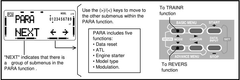
DATA RSET — Data Reset (PARA Function)
The Date Reset function is used to clear out an existing set of model data. This may be used to input new model settings into a memory used for another model. It resets all data to initial values.
Resetting the memory
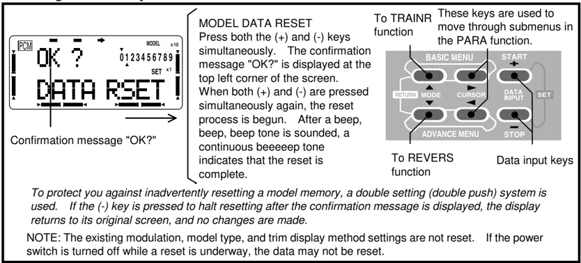
To protect you against inadvertently resetting a model memory, a double setting (double push) system is used. If the (-) key is pressed to halt resetting after the confirmation message is displayed, the display returns to its original screen, and no changes are made.
NOTE: The existing modulation, model type, and trim display method settings are not reset. If the power switch is turned off while a reset is underway, the data may not be reset.
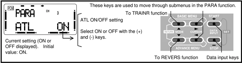
ATL — Adjustable Travel Limit (PARA Function)
The ATL trim function enables the trim lever to function only at the throttle stick idle position and disables trim at high throttle, where it prevents pushrod jamming due to trim changes made at idle.
31
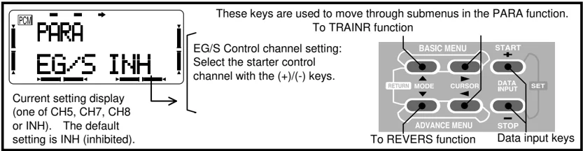
EG/S — Engine Starter (PARA Function)
The Engine Start function activate a switch which turns the (on-board) engine starter on and off with switch H. The engine starter and snap roll functions cannot be used simultaneously.
SETTING METHOD
TYPE — Model Type (PARA Function)
This function is used to select the type of model to be programmed in the current model memory. You may select from aircraft (ACRO), gliders with one or two flap servos (GLID1FLP, GLID2FLP), and helicopters of five swash types (HELISWH1/SWH2/SWH4/SR-3/SN-3).
Swashplate Type Setting Procedure HELISWH1 Type This type’s helicopter has independent aileron and elevator servos linked to the swashplate. Most kits are HELISWH1 type.
HELI SWH2 Type Use SWH2 mixing when the pushrods are positioned as shown in the figure. Elevator operates with a mechanical linkage. With Aileron inputs, the aileron and pitch servos tilt the swashplate left and right; With Pitch inputs, the aileron and pitch servos raise the swashplate up and down.
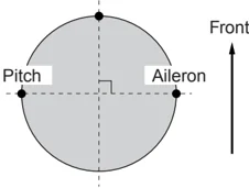
HELI SWH4 Type If the servo inputs are located as shown, use SWH4 Mixing. With Aileron inputs, the aileron and pitch servos tilt the swashplate left and right; With Elevator inputs, the servos tilt the swashplate fore and aft; With Pitch inputs, all four servos raise the swashplate up and down.
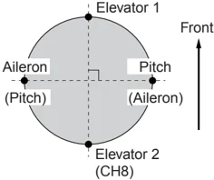
32
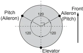
HELI SR-3 Type
If the servo inputs match the figure, use SR-3 Mixing.
With Aileron inputs, the aileron and pitch servos tilt the swashplate left and right;
With Elevator inputs, the three servos tilt the swashplate fore and aft;
With Pitch inputs, all three servos raise the swashplate up and down.
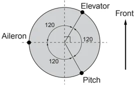
HELI SN-3 Type
Use SN-3 Mixing if the servo inputs match the figure.
With Aileron inputs, the three servos tilt the swashplate left and right;
With Elevator inputs, the elevator and pitch servos tilt the swashplate fore and aft;
With Pitch inputs, all three servos raise the swashplate up and down.
Use the reversing function (REV) as necessary to get the proper aileron, elevator, and pitch operations.
SETTING METHOD
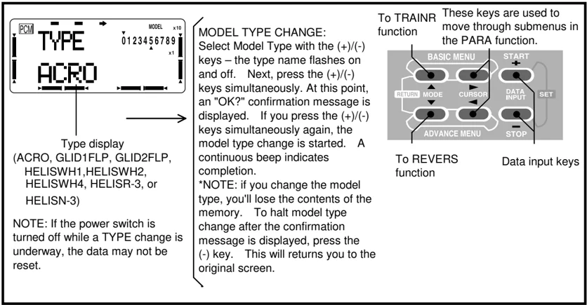
Type display (ACRO, GLID1FLP, GLID2FLP, HELISWH1,HELISWH2, HELISWH4, HELISR-3, or HELISN-3)
NOTE: If the power switch is turned off while a TYPE change is underway, the data may not be reset.
MODEL TYPE CHANGE: Select Model Type with the (+)/(-) keys – the type name flashes on and off. Next, press the (+)/(-) keys simultaneously. At this point, an "OK?" confirmation message is displayed. If you press the (+)/(-) keys simultaneously again, the model type change is started. A continuous beep indicates completion.
*NOTE: if you change the model type, you'll lose the contents of the memory. To halt model type change after the confirmation message is displayed, press the (-) key. This will returns you to the original screen.
To TRAINR function These keys are used to move through submenus in the PARA function.
BASIC MENU START + RETURN MODE CURSOR DATA INPUT SET ADVANCE MENU STOP
To REVERS function Data input keys
33
MOD — Modulation Select (PARA Function)
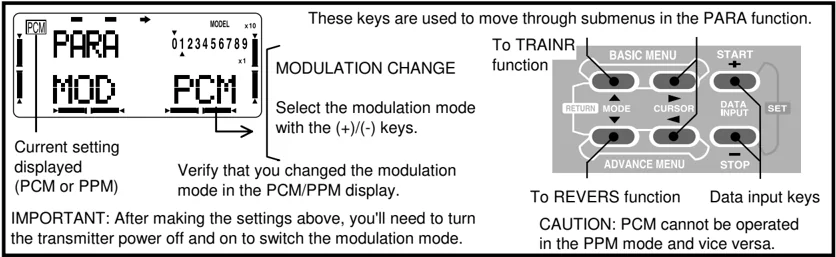
The Modulation menu is used to select the PCM or PPM mode of transmission, to match the receiver being used (PCM = Pulse Code Modulation, and PPM = Pulse Position Modulation). When using an FM receiver, you should select the PPM mode. Note that you have to turn your transmitter on and off before a modulation change becomes effective.
Changing your transmitter’s modulation
AIL2—Second Aileron (PARA Function)
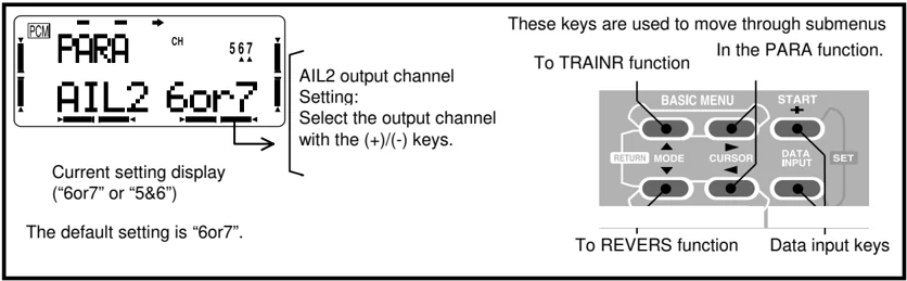
AIL2 outputs the second aileron to channel 5. (In the "ACRO" and "GLID1FLP" modes.) A mode that outputs second aileron to channel 6 or 7 ("6or7"), the same as normal, or a mode that outputs second aileron to channels 5 and 6 ("5&6") can be selected. When using the flaperon or aileron differential function with a 5-channel receiver, select the "5&6" mode.
SETTING METHOD
34
TRAINR — Trainer Functions
The Trainer function is used to train novice pilots using an optional trainer cord connecting two transmitters. The instructor may choose that all channels be controlled by the student, or that certain designated channels be operated by the student and the remainder by the instructor. Pulling on Switch F allows the student to control the selected channels on the model. You may use your 8UA transmitter with any transmitter of the SKYSPORT, Super 7, or 1024Z series of transmitters. Simply plug the optional trainer cord (sold separately) into the trainer connection on each transmitter. Note that when the trainer function is active, the snap roll function is automatically deactivated.
Trainer function operation modes:
"FUNC": When the trainer switch is ON, the channel set to this mode can be controlled by the student by using the mixing set at the instructor's transmitter. "OFF": The channel set to this mode cannot be controlled by the student even when the trainer switch is ON. The set channel can be controlled by the instructor only. "NORM": When the trainer switch is ON, the channel set to this mode can be controlled by the student. The set channel is controlled according to the contents set at the student's transmitter.
Examples:
When the stick channel is set to the "FUNC" mode, helicopter stick operation practice is possible even with a 4VF transmitter (4 channels for aircraft). The practice channel matched to the student level can be set to the "NORM" mode and the other channels can be set to the "OFF" mode and controlled by the instructor.
A few important precautions:
- NEVER turn on the student transmitter power. Collapse the student's antenna.
- ALWAYS set the student transmitter modulation mode to PPM.
- BE SURE that the student and instructor transmitters have identical trim and control motions. Verify by switching back and forth while moving the control sticks.
- FULLY extend the instructor's antenna.
- Always remove the student transmitter RF module (if it is a module-type transmitter).
Setting up Trainer mode
- ACTivate the TRAINR function by pressing the (+) key. (INH the function with the (-) key.)
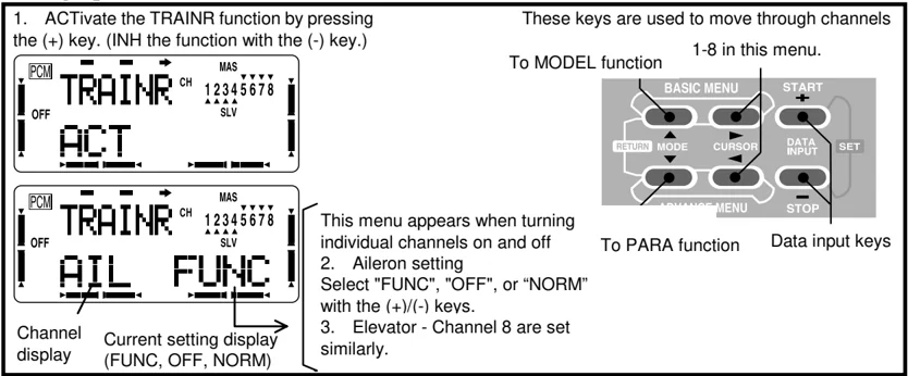
This menu appears when turning individual channels on and off 2. Aileron setting Select "FUNC", "OFF", or "NORM" with the (+)/(-) keys. 3. Elevator - Channel 8 are set similarly.
These keys are used to move through channels 1-8 in this menu. To MODEL function To PARA function Data input keys
35
MODEL — Model Functions
The Model function includes a number of submenus that are used to manage the model memory. This may be better understood by viewing the menu structure on p. 20.
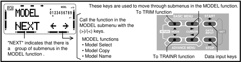
SEL — Model Select (Model Function Submenu)
The Model Select function allows you to choose from all of the different sets of model data stored in the transmitter (eight models can be stored within the transmitter, and data for eight additional models may be selected from the optional DP-16K CAMPac memory module, which is sold separately). The SEL function is used to select the model memory set to be loaded. If you select a model from the memory module, the letters “PAC” on the display will flash on and off.
Choosing another model memory to load
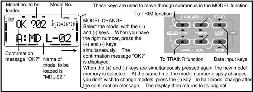
COPY — Copy Menu (Model Function Submenu)
The COPY function is used to copy the current model data into another model memory, which may either be inside the transmitter, or in the optional DP-16K CAMPac memory module. This function is handy to use to start a new model that’s similar to one you have already programmed, and is also handy for copying the current model data into another model memory as a backup. If the data are stored in the memory module, you can easily transfer the settings to friend’s transmitter, which will save a lot of programming time.
36
Copying from one model memory to another
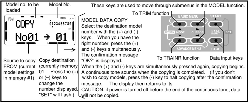
NAME — Model Name (MODEL Function)
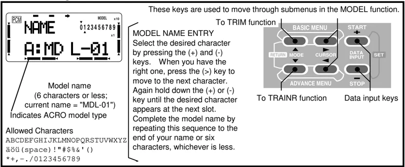
The NAME function may be used to assign the current model memory a name. The model name makes it a lot less confusing since you can easily tell your model memories apart. The name of the model that you assign is displayed at the top left corner of the startup screen. The name can be up to six characters long, and each of the characters may be alphanumeric, space, or symbols (see list below).
The default names assigned by the factory are in the "A:MDL-01" (Model 01) form. Note that the model type is displayed as the single character that appears before the model name on the screen. The code used is A = ACRO (aircraft), H = HELI (helicopter), G = GLID (glider)
Model Naming Instructions
37
TRIM — Trim Settings
The FP-8UAP has digital trims which are different from conventional mechanical trim sliders. Each trim control is actually a two-direction switch. Each time the trim switch is pressed, the trim is changed a selected amount. When you hold the trim lever, the trim speed increases. The current trim position is graphically displayed on the screen. The Trim function includes a number of submenus that are used to manage the trim options. This may be better understood by viewing the menu structure on p. 20.
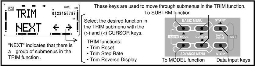
RSET — Trim Reset (TRIM Function Submenu)
The Trim Reset function electronically centers the trims to their default values. Note that the subtrim settings and the trim step rate are not reset by this command.
Resetting trims
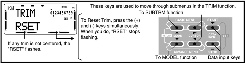
STEP — Trim Step (TRIM Function Submenu)
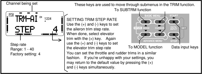
The Trim Step menu may be used to change the rate at which the trim moves when the trim lever is activated. It may be set to a value ranging from 1 to 40 units, depending on the characteristics of the aircraft. Most ordinary aircraft do well with their trim step rate set to about 2 to 10 units.
38
DISP — Trim Reverse Display (TRIM Function Submenu)
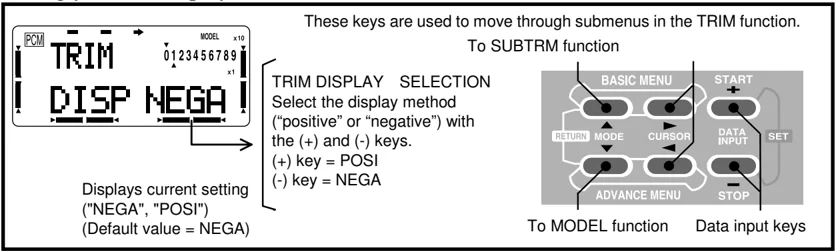
The DISP function swaps the black and white displays in the graphic trim position display shown on the screen. We suggest you try both settings and see which one is better for you. (The reverse display is not affected by the Data Reset command.)
Setting you trim displays
These keys are used to move through submenus in the TRIM function.
SUBTRM — Subtrim Settings
The Subtrim menu is used to make small changes or corrections in the neutral position of each servo. We recommend that you center the digital trims before making subtrim changes, and that you try to keep all of the subtrim values of as small as possible. Otherwise, when the subtrims are large values, the servo’s range of travel is restricted.
The recommended procedure is as follows: zero out both the trims (TRIM RSET menu) and the subtrims (this menu). Next, mount the servo arms and set up your linkages so that the neutral position of the control surface is as close to where it should be as possible. Finally, use a small amount of subtrim to make fine corrections.
Setting Subtrims
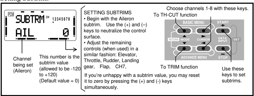
Choose channels 1-8 with these keys.
To TH-CUT function
To TRIM function
Use these keys to set subtrims.
39
TH-CUT — Throttle Cut Function
The Throttle Cut function provides you an easy way to stop the engine by simply flipping a switch with the throttle stick at idle, which commands the throttle servo to move a prescribed amount. The amount of movement is largest at idle and disappears at high throttle. Both the switch’s location and activation direction may be chosen by the owner.
Setting up Throttle Cut Operations
Turn the TH-CUT function ON or OFF by pressing the (+) key ("ON" or "OFF" displayed depending on switch position). Turn off (INH) the function with the (-) key.
To TIMER function
These keys are used to move around in the TH-CUT menu
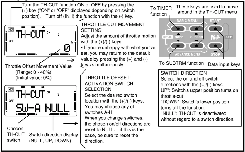
Throttle Offset Movement Value (Range: 0 - 40%) (Initial value: 0%)
Chosen TH-CUT switch
Switch direction display (NULL, UP, DOWN)
THROTTLE CUT MOVEMENT SETTING Adjust the amount of throttle motion with the (+)/(-) keys. • If you’re unhappy with what you’ve set, you may return to the default value by pressing the (+) and (-) keys simultaneously.
THROTTLE OFFSET ACTIVATION SWITCH SELECTION Select the desired switch location with the (+)/(-) keys. You may choose any of switches A-H. When you change switches, the chosen on/off directions are reset to NULL. if this is the case, be sure to reset the direction.
To SUBTRM function Data input keys
SWITCH DIRECTION Select the on and off switch directions with the (+)/(-) keys. UP": Switch's upper position turns on throttle-cut "DOWN": Switch's lower position turns off the function. "NULL": TH-CUT is deactivated without regard to a switch direction.
TIMER — Timer (Stopwatch Function)
The Timer Menu controls an electronic clock that may be used to keep track of time remaining in a competition task window, flying time on a full tank of fuel, amount of time on a battery, etc. The timer’s settings may be set independently for each model, and is automatically updated each time the model is changed. The timer can be set to count up to 59 minutes 59 seconds.
You may choose either a count-down or count-up timer mode. When the timer switch is turned on, the down timer starts from the chosen time and displays the amount of time remaining. If the timer exceeds the time setting, it continues to count and displays a minus sign (–) in front of the numbers. The count up timer starts at 0 and displays the elapsed time. In either timer mode, the timer beeps once each minute. During the last ten seconds, there’s a beep each second.
The timer screen can be easily displayed or cleared by pressing the CURSOR key at the startup screen when the transmitter power is turned on. The timer is started by the plus (+) key and stopped by the (–) key. When the DATA INPUT "+" and "–" keys are pressed simultaneously, the timer is reset. If the DATA INPUT keys (+ and –) are pressed simultaneously after the timer is started, the timer is reset, but continues to count up or down. The starting and stopping switches may be chosen among any of Switch A — Switch H, activated by the throttle stick (STK-3) or activated by the power switch (POWER SW). The ON and OFF directions can also be freely selected except the power switch. Using the throttle stick is particularly convenient if you’re keeping track of fuel remaining, or for an electric, how much battery is left. Regardless of which switch is chosen, the timer can also
40
be turned on and off with the DATA INPUT keys.
Using the 8UA Timer Function
Timer's minute setting seconds setting Timer Type display (UP or DN)
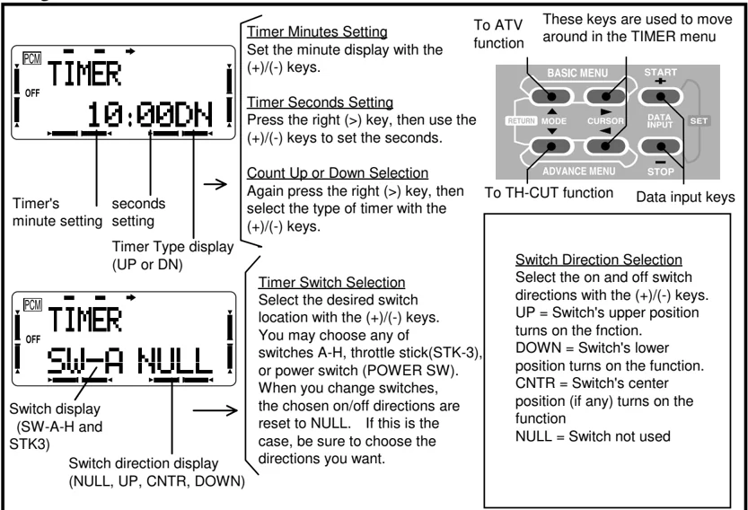
Timer Minutes Setting Set the minute display with the (+)/(-) keys.
Timer Seconds Setting Press the right (>) key, then use the (+)/(-) keys to set the seconds.
Count Up or Down Selection Again press the right (>) key, then select the type of timer with the (+)/(-) keys.
To ATV function These keys are used to move around in the TIMER menu
BASIC MENU START RETURN MODE CURSOR DATA INPUT SET ADVANCE MENU STOP
To TH-CUT function Data input keys
Switch display (SW-A-H and STK3) Switch direction display (NULL, UP, CNTR, DOWN)
Timer Switch Selection Select the desired switch location with the (+)/(-) keys. You may choose any of switches A-H, throttle stick(STK-3), or power switch (POWER SW). When you change switches, the chosen on/off directions are reset to NULL. If this is the case, be sure to choose the directions you want.
Switch Direction Selection Select the on and off switch directions with the (+)/(-) keys. UP = Switch's upper position turns on the fnction. DOWN = Switch's lower position turns on the function. CNTR = Switch's center position (if any) turns on the function NULL = Switch not used
If you want motion of the throttle stick to activate the timer (STK-3), you'll need to set the ON-OFF stick position and direction for the stick to turn the timer on and off as follows:
- First, position the throttle stick so that it's in the location where you want to have the timer switch on and off.
- Next, press both of the (+)/(-) keys simultaneously to make the transmitter memorize the location.
- Now you'll choose which side of the set point is on, and which side is off. If you want to turn on the timer at the hight throttle stick position, press the (+) key. If you want to turn on the timer at the low throttle stick position, press the (-) key. After you choose the direction, an up or down arrow is displayed at the top (high) or bottom (low) side of "3" at the top right corner of the display, to confirm the switching direction you have chosen. Move the throttle stick back and forth to confirm that the timer starts and stops as desired.
AIRCRAFT (ACRO) ADVANCE MENU FUNCTIONS
The next section of this manual, pages 43 to 51, describe how to use the functions in the ADVANCE MENU with the aircraft (ACRO) model mode. Some of these functions are also used with glider model modes (GLID1FLP, GLID2FLP).
- PMIX-1-7 ........ Programmable mixers 1-7 ........ 43
- FLPRON ........ Flaperon (combined flaps & ailerons) ........ 45
- FLAPTRM ........ Flap trim (camber adjustment) ........ 46
- AI-DIF ........ Aileron differential ........ 46
- ABRAKE ........ Airbrake ........ 47
- ELE→FL ........ Elevator→Flap mixing ........ 48
- V-TAIL ........ V-tail mixing ........ 48
- ELEVON ........ Elevon mixing (for tailless models) ........ 49
- ALVATR ........ Ailvator (differential elevator control) ...49
- SNP ........ Snap roll ........ 50
- TH-DLY ........ Throttle delay ........ 51
- TH→NDL ........ Throttle needle ........ 51
42
PMIX-1-7 — Programmable Mixers 1-7
Your 8UA system contains seven separate programmable mixers with unique mixing capabilities. You may use mixing to correct bad tendencies of the aircraft during aerobatics, and to make operation more pleasant. Besides mixing between arbitrary channels, the mixers may be linked with the Advance menus in the 8UA. They can also be set to provide fixed offsets. You may select which switch activates your mixers. The method to be used to program mixers is given for Mixer #1, but Mixer #2-5 may be programmed in an identical fashion. Mixer #6-7’s mixing rate can be set with a 5-point curve.
The Link function is used to ‘link’ programmable mixers with other mixing menus. For example, you might wish to use a PMIX to provide rudder→aileron mixing for better knife-edge flight in a model with flaperons using the Flaperon (FLPRON) mixing function. With two aileron servos plugged into receiver channels CH1 and CH6, mixing only appears at the CH1 aileron when rudder is commanded. When the Link function is turned on, this situation is easily corrected, and mixing is applied to both CH1 and CH6.
The trim selection option allows you to choose whether the trim from the master also affects the slave channel. The offset function lets you offset the mixing curve for the slave channel relative to the master channel, a feature which is handy for mixing with non-centering functions such as throttle or knobs as the master channel.
Switch selection: you may choose an ON/OFF switch for each of the programmable mixers from the eight switches A - H. In addition, the throttle stick (CH3) may be used to turn the programmable mixers ON and OFF.
Using the Programmable mixers
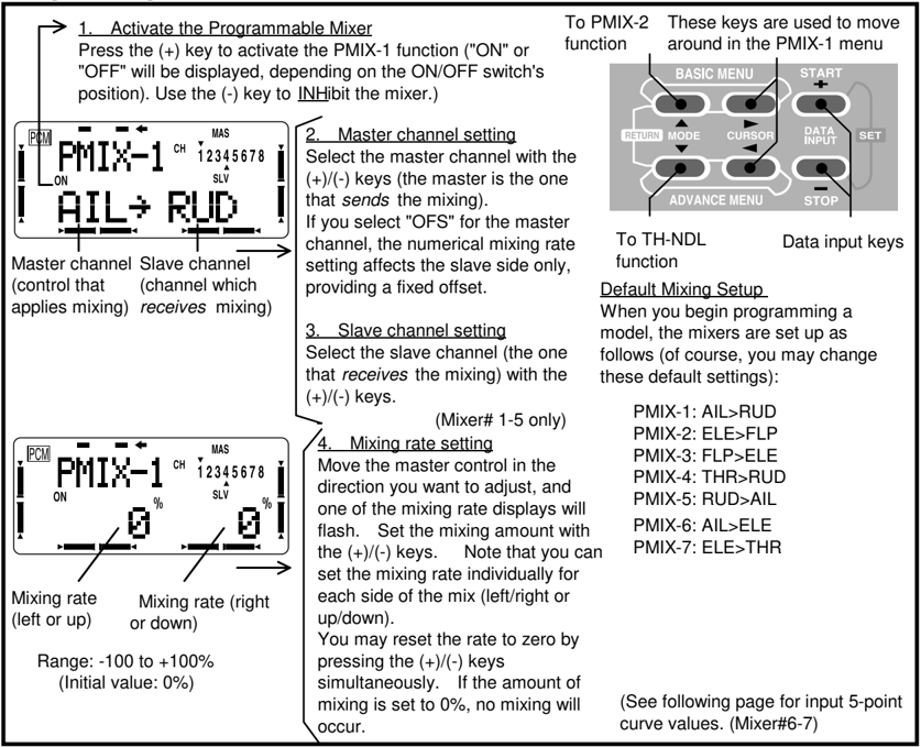
To PMIX-2 function
These keys are used to move around in the PMIX-1 menu
To TH-NDL function
Data input keys
Default Mixing Setup When you begin programming a model, the mixers are set up as follows (of course, you may change these default settings):
PMIX-1: AIL>RUD PMIX-2: ELE>FLP PMIX-3: FLP>ELE PMIX-4: THR>RUD PMIX-5: RUD>AIL PMIX-6: AIL>ELE PMIX-7: ELE>THR
(See following page for input 5-point curve values. (Mixer#6-7)
43
(Continued from preceding page)
Set rate Range:-100 to +100% (Initial value: 0%)
(Mixer# 6-7 only) 4. Input 5-point curve values Select the curve position "POS1" with the CURSOR keys and set the rate with the (+)/(-) keys. -If you're unhappy with what you've set, you may return to the default value by presing the (+) and (-) keys simultaneously.
Link function ON/OFF indicator
5. Link function setting Turn the Link function ON or OFF with the (+)/(-) keys. When the Link function is ON, ">" is displayed after the slave channel on the screen.
Trim ON/OFF indicator
(Mixer# 1-5 only) 6. Trim setting This couples the master channel's trim with the slave function. Select ON/OFF with the (+)/(-) keys.
Displays offset position
(Mixer# 1-5 only) 7. Offsetting neutral mix point If you want the mix to occur somewhere besides master neutral, hold the master channel control in the desired position, and store the offset position by pressing the (+)/(-) keys simultaneously.
Current on/off switch Displays ON/OFF switch direction
8. Switch selection Choose the desired mixer ON/OFF switch with the (+)/(-) keys.
9. ON/OFF Direction Set the ON/OFF directions with the (+)/(-) keys. NULL = Normal operation regardless of switch setting UP = Switch upper or rear position turns on the function CNTR = Center position of 3-position switch turns on the function DOWN = Switch lower or forward position turns on the function UP/C = Uper and center position of 3-position switch turn on the function. C/DN = Center and lower position of 3-position switch turn on the function.
• If you select "STK-3" to turn mixer on and off, you'll need to set the switching position and direction. To do so, first position the throttle stick where you want switching to occur. Next, enter the stick position into memory by pressing the (+)/(-) keys simultaneously. (a percentage will be displayed on the screen. If you want mixing turned on at the high throttle side of the set position, press the (+) key. If you want mixing on at the low throttle side, press the (-) key. An arrow is displayed above or below the small "3" at the right top corner of the screen to verify proper switching direction. When you think you're done, move the throttle stick and check if programmable mixing switches on and off in accordance with your settings.
44
FLPRON — Flaperon Mixing
The Flaperon mixing function uses two servos to individually control two ailerons, combining the aileron function with the flap function. For a flap effect, the ailerons can be raised and lowered simultaneously. Of course, aileron function, where the two controls move in different directions, is also performed. The up and down travel of the left and right ailerons can be adjusted independently, so you can also get a differential effect. Left and right flap travel can be adjusted individually. You can combine the Flaperon function with the airbrake function, to get steep descents without building up airspeed, which is very convenient for small or narrow fields. To take advantage of the flaperon mixing function, you’ll need to connect the right aileron servo to CH1 (AIL) and the left aileron servo to CH6 (FLP).
NOTE: Only one of the three functions flaperon, aileron differential, or elevon can be used at a time. All three functions cannot be activated simultaneously. The last function activated overrides the others.
Setting up the Flaperon function
Turn the FLPRON function ON by pressing the (+) key ("ON" displayed). Turn off (INH) the function with the (-) key.
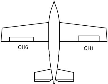
Amount of aileron travel for left aileron stick
Range: -120 to +120%)
(Initial setting +100%)
Amount of aileron travel for right stick
Range: -120 to +120%)
(Initial setting +100%)
-
Right aileron adjustment
Move the aileron stick in the direction you want to adjust and set the value with the (+)/(-) keys. -
Left aileron adjustment
Again move the aileron stick in the direction you want to adjust and set the value as before.
• If you're unhappy with what you've set, you may return to the default value by pressing the (+) and (-) keys simultaneously.
To FLPTRM function
These keys are used to move around in the FLPRON menu
To MIX-7 function
Data input keys
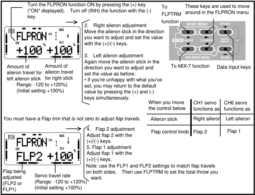
You must have a Flap trim that is not zero to adjust flap travels.
Flap being adjusted (FLP2 or FLP1)
Servo travel rate (Range: -120 to +120%) (Initial setting +100%)
-
Flap 2 adjustment
Adjust flap 2 with the (+)/(-) keys. -
Flap 1 adjustment
Adjust flap 1 with the (+)/(-) keys.
Note: use the FLP1 and FLP2 settings to match flap travels on both sides. Then use FLPTRM to set the total throw you want.
| When you move the control below | CH1 servo functions as | CH6 servo functions as |
|---|---|---|
| Aileron stick | Right aileron | Left aileron |
| Flap control knob | Flap 2 | Flap 1 |
45