REVOLU — Revolution Mixing (Normal)
The Normal revolution function mixes pitch commands into rudder in order to suppress the torque generated by changes in the main rotor’s pitch angle. Three are three different settings of revolution mixing available: normal (NORM), idle-up 1 (IDL1), and idle-up 2 (IDL2). Only normal revolution mixing is displayed on the Basic Menu.
The revolution mixing rate can be input on a 5-point curve. For a clockwise-turning rotor, the rudder is mixed in the clockwise direction when pitch is increased; for a counterclockwise-turning rotor, the opposite setting is made. The operating direction setting is changed by changing the signs of the numbers in the curve from plus (+) to minus (-) and vice versa:
Clockwise rotation: -50, -25, 0, +25, +50% from low throttle Counterclockwise rotation: +50, +25, 0, -25, -50% from low throttle
These numbers are the default initial values. You should replace them with the actual values that work best for your model.
Procedure for adjusting revolution mixing
This procedure assumes that your model is trimmed, and no tail rotor command is needed in hover.
- Throttle low-side adjustment (between idle and hovering)
Repeatedly takeoff and hover and return to land. Adjust revolution mixing so that raising and lowering the throttle does not cause a sudden fuselage heading change. If the nose points left when landing from hover or when taking off, the low-side mixing rate is too high. If the nose points in the opposite direction, the mixing rate is too small. Note that the nose direction may not become stable when taking off if the helicopter is not steady before takeoff, or if the rotor speed does not rise.
- Throttle high-side setting (between hovering to high-power climbing)
Apply throttle while hovering to climb and then descend back to hover. Adjust revolution mixing so that the nose does not change heading when the throttle is raised and lowered as in the low-side adjustment given above.
Revolution Mixing Setting
Top arrow indicates the current stick position (2 arrows means it's between points)
Curve points 1-5 The bottom arrow shows the point on the five-point curve currently being set.
To ATV function
These keys are used to move between the five points in the REVOLU function.
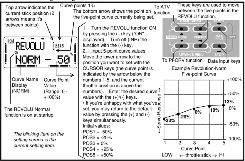
PCM REVOLU ON NORM - 50 % 1 2 3 4 5
Curve Name Display (NORM) Curve Point Value (Range: 0 - +100%)
The REVOLU Normal function is on at startup.
The blinking item on the setting screen is the current setting item.
- Turn the REVOLU function ON by pressing the (+) key ("ON" displayed). Turn off (INH) the function with the (-) key.
- Input 5-point curve values Move the lower arrow to the position you want to set with the CURSOR keys (the curve point is indicated by the arrow below the numbers 1-5, and the current throttle position is above the numbers). Enter the desired curve value with the (+)/(-) keys. • If you're unhappy with what you've set, you may return to the default value by pressing the (+) and (-) keys simultaneously. Initial values: POS1 = -50% POS2 = -25% POS3 = 0% POS4 = +25% POS5 = +50%
BASIC MENU RETURN MODE CURSOR DATA INPUT SET ADVANCE MENU STOP
To PI-CRV function Data input keys
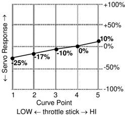
Example Revolution-Norm Five-point Curve
← Servo Response → +100% +50% 13% 0% -20% 0% 10% -33% -50% -100% 1 2 3 4 5 Curve Point LOW ← throttle stick → HI
72
SWASH – Swash AFR
You can use Swash AFR rate settings to reduce (or increase) the function rate when SWH2, SWH4, SR-3, or SN-3 is selected as the swash type. The function rate reduction or increase for the aileron, elevator, and pitch may be controlled by this menu.
Setting Swash AFR rate values
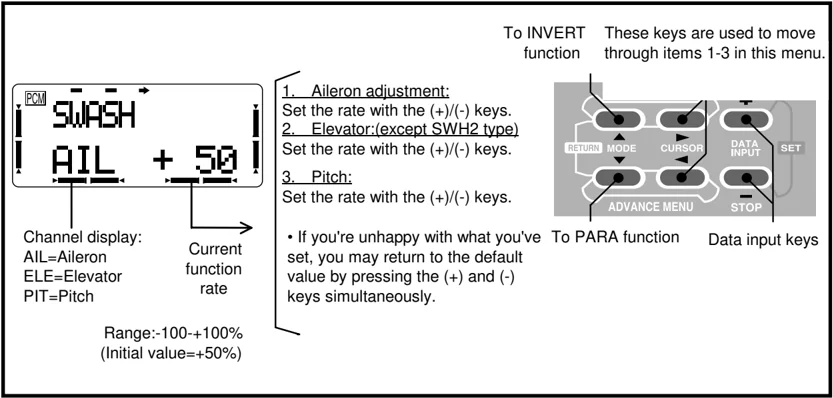
To INVERT function These keys are used to move through items 1-3 in this menu.
- Aileron adjustment: Set the rate with the (+)/(-) keys.
- Elevator:(except SWH2 type) Set the rate with the (+)/(-) keys.
- Pitch: Set the rate with the (+)/(-) keys.
• If you're unhappy with what you've set, you may return to the default value by pressing the (+) and (-) keys simultaneously.
To PARA function Data input keys
Channel display: AIL=Aileron ELE=Elevator PIT=Pitch
Current function rate
Range:-100~+100% (Initial value=+50%)
73
INVERT — Inverted Flight Function
The Invert function is used to make inverted flight easier. Instead of having to learn to reverse controls mentally, when switch H is moved forward (and the INVERT function is activated), the direction of operation of the elevator, rudder, and pitch servos is reversed. In addition, the pitch servo throw is reduced to about two-thirds of the normal throw.
Before using the INVERT function, be sure that you helicopter is trimmed for good normal flight. You’ll need to set up your linkages carefully to use the INVERT function.
You can adjust the pitch curve and cross position setting when this function is ON with the inverted pitch curve (PI-CRV, INVR) and inverted cross position (INVERT, CROSS) menus in the Advance Menu. You can plug your gyro into CH7, and its sensitivity may be controlled by switch C.
INVERT Function Programming
Turn off the INVERT function (move switch H to the rear position) and select a servo arm that provides the proper negative and positive pitch angles to allow autorotation. Hook up the linkage to the servo.
Since the normal flight pitch curve uses NORM, IDL1, IDL2, and HOLD, set up your helicopter for trimmed flight in hover, forward flight, and autorotation. To program the inverted flight pitch, turn on the INVERT function (switch F set to forward position) and activate the pitch curve inverted (PI-CRV, INVR) menu within the Advance Menu to program the pitch. Whenever INVERT is activated, the elevator, flap, and pitch servos respond in the opposite direction to how they respond for forward flight. In addition, elevator and rudder trim is also reversed. The hovering pitch function is active only at the forward flight side.
You can set the inverted cross position at the "INVERT, CRSS" screen within the Advance Menu (see p. 77).
Setting up inverted flight mode
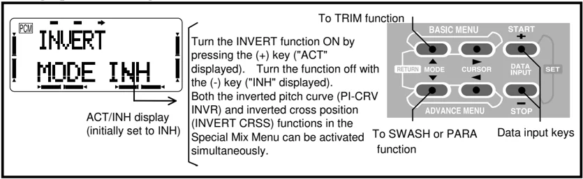
To TRIM function
ACT/INH display (initially set to INH)
To SWASH or PARA function
Data input keys
74
TH-CUT — Throttle Cut
The TH-CUT function is used to kill the engine at the end of a flight. The engine can be stopped with one touch with switch F (the momentary trainer switch is the initial setting, but you may select another). This function eliminates the need to move the trim to kill the engine and then move back to the idling position after each flight. When the throttle stick is lower than the function ON/OFF set point throttle position (normally a little above idle), the TH-CUT function responds to the operation of the switch, and the throttle servo moves to its defined position.
The TH-CUT function will protect you from accidentally shutting off the engine. When the throttle stick is above the set point, the TH-CUT function is not activated even if the throttle cut switch is operated. In addition, you must move the throttle stick back below the set point before the TH-CUT function can be reset, to avoid sudden engine acceleration.
TH-CUT setup
Hook up and adjust the throttle linkage so that full throttle fully opens the carburetor, and use the digital trim to make the engine idle at low throttle. Turn on the throttle cut switch (switch F) and select the amount of offset to be just large enough in the "–" direction (low throttle) to fully close the carburetor.
If you prefer, you may select another switch and ON-OFF direction. For safety, always activate the TH-CUT function and use it.
Setting up the Throttle Cut function
-
Turn the TH-CUT function ON or OFF by pressing the (+) key ("ON" or "OFF" displayed depending on switch F's position). Turn off (INH) the function with the (-) key.
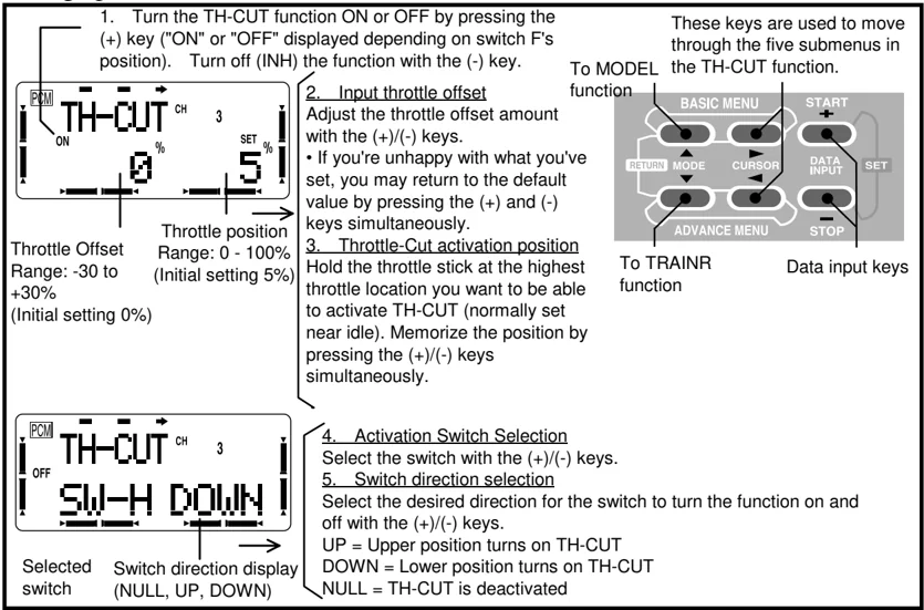 PCM TH-CUT CH 3
ON 0 % SET 5 %
Throttle Offset Range: -30 to +30% (Initial setting 0%)
Throttle position Range: 0 - 100% (Initial setting 5%)
-
Input throttle offset Adjust the throttle offset amount with the (+)/(-) keys. • If you're unhappy with what you've set, you may return to the default value by pressing the (+) and (-) keys simultaneously.
 PCM TH-CUT CH 3
ON 0 % SET 5 %
Throttle Offset Range: -30 to +30% (Initial setting 0%)
Throttle position Range: 0 - 100% (Initial setting 5%)
These keys are used to move through the five submenus in the TH-CUT function. To MODEL function BASIC MENU START + RETURN MODE CURSOR DATA INPUT SET ADVANCE MENU STOP To TRAINR function Data input keys
-
Throttle-Cut activation position Hold the throttle stick at the highest throttle location you want to be able to activate TH-CUT (normally set near idle). Memorize the position by pressing the (+)/(-) keys simultaneously.
-
Activation Switch Selection Select the switch with the (+)/(-) keys.
-
Switch direction selection Select the desired direction for the switch to turn the function on and off with the (+)/(-) keys. UP = Upper position turns on TH-CUT DOWN = Lower position turns on TH-CUT NULL = TH-CUT is deactivated
PCM TH-CUT CH 3 OFF SW-H DOWN Selected switch Switch direction display (NULL, UP, DOWN)
75
HELICOPTER (HELISWH1/SWH2) ADVANCE MENU FUNCTIONS
Pages 77 to 90 describe the Advance menu functions for both helicopter model types (HELISWH1, HELISWH2, HELISWH4, HELISR-3, HELISN-3). Helicopter Basic Menus are in pages 70 to 75.
\begin{tabular}{llr} TH-CRV & Throttle Curve & 77 \ TH-HLD & Throttle Hold & 79 \ OFST-1-2 & Offset 1-2 & 80 \ DELAY & Delay & 80 \ PMIX-1-2 & Programmable Mixing & 81 \ HOV-TH & Hovering Throttle & 83 \ HOV-PI & Hovering Pitch & 83 \ GYRO & Gyro Mixing & 84 \ GOVrpm & Governor Mixing & 84 \ TH-NDL & Throttle Needle Mixing & 86 \ INVERT CROSS & Inverted Cross Position & 87 \ REVOLU & Revolution Mixing (Normal, Idle-up 1 & 2) & 87 \ PI-CRV & Pitch Curve (Normal, Idle-up 1 & 2) & 89 \ \end{tabular}
76
TH-CRV — Throttle Curve (Normal, Idle-Up 1, Idle-Up 2)
You can use Throttle Curve menus to program a five-point curve so that the engine speed responds the way you like relative to movement of the throttle stick. You can set each of the five points over a 0% to 100% range.
There are three throttle curves: normal (NORM), idle-up 1 (IDL1), and idle-up 2 (IDL2). Only the basic normal throttle curve is displayed in the Basic Menu, but all the curves may be programmed in the Advance Menu. For your convenience, the normal curve can be programmed in either the Basic or Advance Menu, and it is automatically updated in both places. Switch G is programmed so that you may change between the normal (NORM), idle-up 1 (IDL1), and idle-up 2 (IDL2) curves.
Normal Curve Adjustment Method
The normal throttle curve (TH-CRV NORM) function is used to produce the basic throttle curve for flight near hover. It is used along with the normal pitch curve (PI-CRV NORM) so that the helicopter flies with constant rotor RPM. The normal throttle curve function is ON at startup.
I dle-up 1 and 2 Curve Adjustment Method
The idle-up curves should be programmed so that the engine maintains constant RPM even when the pitch is reduced during flight. The curves should be matched to loops, rolls, and other maneuvers, and are divided into idle-up curve 1 and idle-up curve 2. The TH-CURV functions for IDL1 and IDL2 curves will not operate until the OFST-1 and OFST-2 functions are activated.
!
77
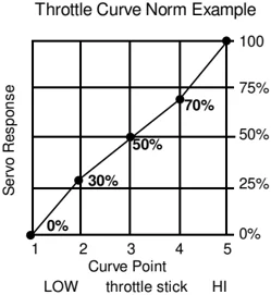
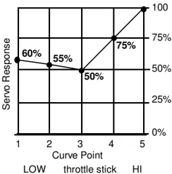
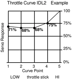
Inputting the Throttle Curve in Normal, Idle-up 1, and Idle-up 2
The Throttle Curve Normal function is on at startup.
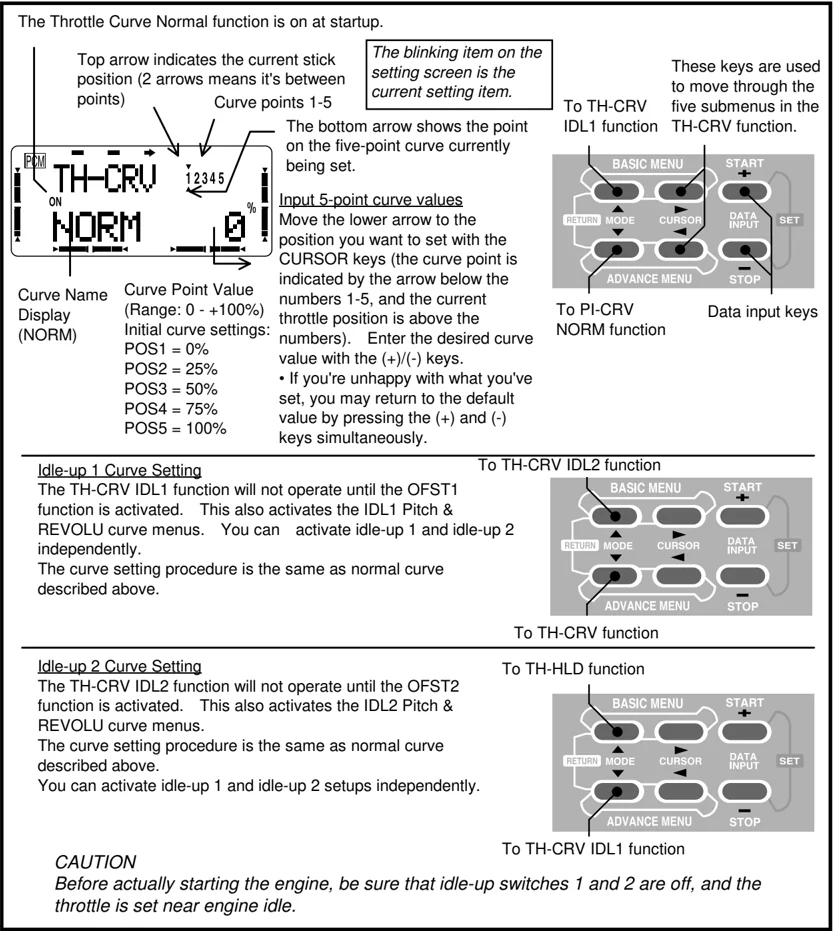
Top arrow indicates the current stick position (2 arrows means it's between points) Curve points 1-5 The bottom arrow shows the point on the five-point curve currently being set.
The blinking item on the setting screen is the current setting item.
Curve Name Display (NORM) Curve Point Value (Range: 0 - +100%) Initial curve settings: POS1 = 0% POS2 = 25% POS3 = 50% POS4 = 75% POS5 = 100%
Input 5-point curve values Move the lower arrow to the position you want to set with the CURSOR keys (the curve point is indicated by the arrow below the numbers 1-5, and the current throttle position is above the numbers). Enter the desired curve value with the (+)/(-) keys. • If you're unhappy with what you've set, you may return to the default value by pressing the (+) and (-) keys simultaneously.
These keys are used to move through the five submenus in the TH-CRV function.
To TH-CRV IDL1 function To PI-CRV NORM function Data input keys
Idle-up 1 Curve Setting
The TH-CRV IDL1 function will not operate until the OFST1 function is activated. This also activates the IDL1 Pitch & REVOLU curve menus. You can activate idle-up 1 and idle-up 2 independently. The curve setting procedure is the same as normal curve described above.
To TH-CRV IDL2 function To TH-CRV function
Idle-up 2 Curve Setting
The TH-CRV IDL2 function will not operate until the OFST2 function is activated. This also activates the IDL2 Pitch & REVOLU curve menus. The curve setting procedure is the same as normal curve described above. You can activate idle-up 1 and idle-up 2 setups independently.
To TH-HLD function To TH-CRV IDL1 function
CAUTION Before actually starting the engine, be sure that idle-up switches 1 and 2 are off, and the throttle is set near engine idle.
78
TH-HLD — Throttle Hold
The Throttle Hold function holds the engine throttle in the idling position and disengages it from the throttle stick, whenever switch E is activated. It is commonly used during autorotation. You can set the throttle position to be held over a -50 to +50% range centered about the throttle idle position. The throttle hold function also includes a rudder offset option.
Rudder offset at throttle hold
The rudder offset function contained in throttle hold is used to offset the tail rotor pitch neutral position during autorotation. It is set to keep the fuselage from rotating only when the throttle hold function is active.
You may also input a time delay for the offset to be implemented (to prevent sudden trim changes) in the DELAY menu within Advance menu (page 72).
Setting up Throttle Hold
- Turn the TH-HLD function ON by pressing the (+) key ("ON" or "OFF" displayed depending on SW-E position). The hovering pitch curve function is also activated. Turn off (INH) the function with the (-) key.
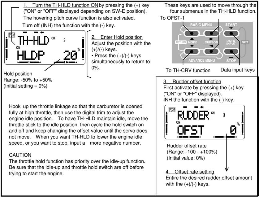
Hold position Range: -50% to +50% (Initial setting = 0%)
These keys are used to move through the four submenus in the TH-HLD function. To OFST-1 To TH-CRV function Data input keys
- Enter Hold position Adjust the position with the (+)/(-) keys. • Press the (+)/(-) keys simultaneously to return to 0%.
Hooki up the throttle linkage so that the carburetor is opened fully at high throttle, then use the digital trim to adjust the engine idle position. To have TH-HLD maintain idle, move the throttle stick to the idle position, then cycle the hold switch on and off and keep changing the offset value until the servo does not move. When you want TH-HLD to lower the engine idle speed, or you want to stop, input a more negative number.
CAUTION The throttle hold function has priority over the idle-up function. Be sure that the idle-up and throttle hold switch are off before trying to start the engine.
- Rudder offset function First activate by pressing the (+) key ("ON" or "OFF" displayed). INH the function with the (-) key.
Rudder offset rate (Range: -100 - +100%) (Initial value: 0%)
- Offset rate setting Entire the desired rudder offset amount with the (+)/(-) keys.
OFST-1-2-iv — Offsets 1, 2 & iv
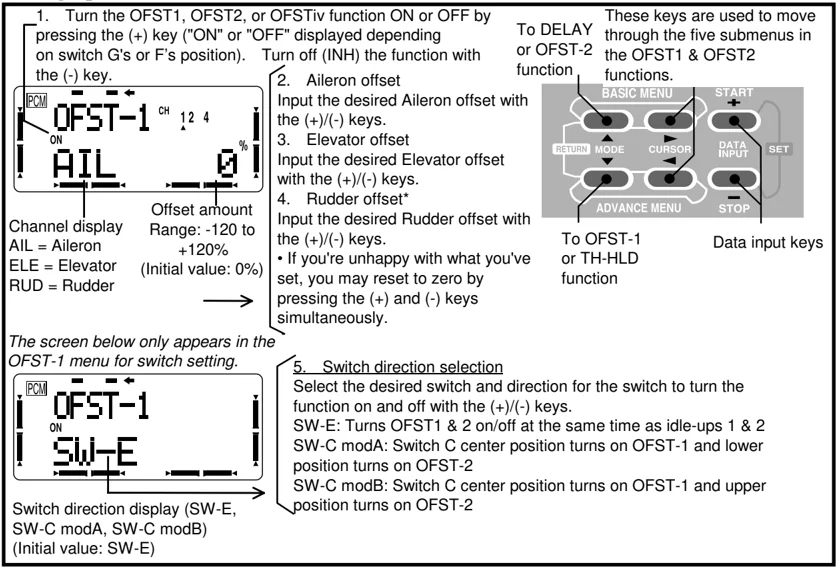
The Offset 1, Offset 2, and Offset iv functions are used to offset (change the neutral position) of the aileron, elevator, and rudder when switch G is used to switch to idle-up 1 (or 2) or switch F is used to switch to inverted flight. This function may be used to automatically change the trim of a helicopter flying at high speed. A clockwise-rotation rotor helicopter tends to drift to the right at high speed, so an aileron offset may be applied to offset the helicopter to the left. You can use the DELAY function to make a smooth transition between the differing neutral settings.
The necessary elevator offset varies with model geometry, so it must be determined by noting pitch changes at high speed. The rudder offset is affected by both revolution mixing (page 72), and trim (overall level movement) with the offset function. When the offset function is ON, also the electronic trim levers will operate, so the trim amount in these flight modes is automatically input to each offset amount.
The activating switches are initially set so that offset 1 and offset 2 are on at the same time as the idle-up 1 and idle-up 2 functions, switched by Switch G. If desired, the offset function ON/OFF operation can be changed to switch C. This may only be done in the OFST-1 menu, and not in the OFST-2 menu.
Setting up Offsets 1, 2, & iv
DELAY — Delay Function
The Delay function provides a smooth transition between the trim positions whenever offset, revolution mixing, or throttle hold functions are turned on and off. You may set different delay times for aileron, elevator, and rudder. With a 50% delay setting, the servo takes about a half-second to move to its new position, quite a long time. Normally a 10-15% delay is used.
80
Setting Delays
The Delay function is automatically activated when either Offset, Revolution mixing, or Throttle hold are activated.
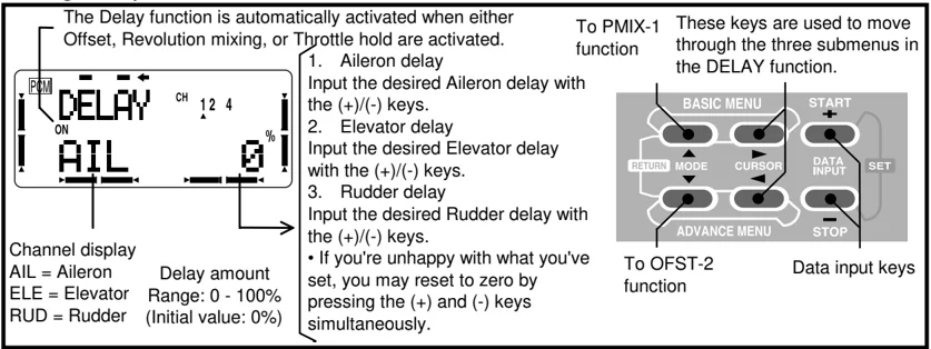
Channel display AIL = Aileron ELE = Elevator RUD = Rudder
Delay amount Range: 0 - 100% (Initial value: 0%)
- Aileron delay Input the desired Aileron delay with the (+)/(-) keys.
- Elevator delay Input the desired Elevator delay with the (+)/(-) keys.
- Rudder delay Input the desired Rudder delay with the (+)/(-) keys.
- If you're unhappy with what you've set, you may reset to zero by pressing the (+) and (-) keys simultaneously.
To PMIX-1 function These keys are used to move through the three submenus in the DELAY function.
To OFST-2 function Data input keys
PMIX-1-2 — Programmable Mixers 1-2
In the helicopter mode, your T8UA system contains two separate programmable mixers with unique mixing capabilities. You may use mixing to correct any tendencies of the helicopter during aerobatics that you want to eliminate, making operation more pleasant. Besides mixing between arbitrary channels, the mixers may be linked with the Advance menus in the T8UA, or the mixing curve can be offset relative to the master's neutral. You may select which switch activates your mixers from the eight switches A-G or throttle, and you may choose whether the trim from the master also affects the slave channel.. The Link function is used to 'link' programmable mixers with other mixing menus.
Mixer Initial Settings
The default channels for Mixers 1 & 2 are set to frequently-used mixing combinations as follows: PMIX-1 = AIL→ELE, PMIX-2 = ELE→THR. The programming method is given for Mixer #1; the second mixer may be programmed in an identical fashion.
- Activate the Programmable Mixer Press the (+) key to activate the PMIX-1 function ("ON" or "OFF" will be displayed, depending on the ON/OFF switch's position). Use the (-) key to INHiBit the mixer.)
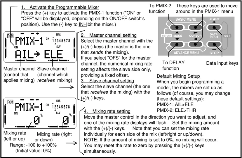
Master channel Slave channel (control that (channel which applies mixing) receives mixing)
Mixing rate Mixing rate (right (left or up) or down) Range: -100 to +100% (Initial value: 0%)
- Master channel setting Select the master channel with the (+)/(-) keys (the master is the one that sends the mixing). If you select "OFS" for the master channel, the numerical mixing rate setting affects the slave side only, providing a fixed offset.
- Slave channel setting Select the slave channel (the one that receives the mixing) with the (+)/(-) keys.
- Mixing rate setting Move the master control in the direction you want to adjust, and one of the mixing rate displays will flash. Set the mixing amount with the (+)/(-) keys. Note that you can set the mixing rate individually for each side of the mix (left/right or up/down). NOTE: If the amount of mixing is set to 0%, no mixing will occur. You may reset the rate to zero by pressing the (+)/(-) keys simultaneously.
To PMIX-2 function These keys are used to move around in the PMIX-1 menu
To DELAY function Data input keys
Default Mixing Setup When you begin programming a model, the mixers are set up as follows (of course, you may change these default settings): PMIX-1: AIL>ELE PMIX-2: ELE>THR
81
(Continued from preceding page)
Link function ON/OFF indicator
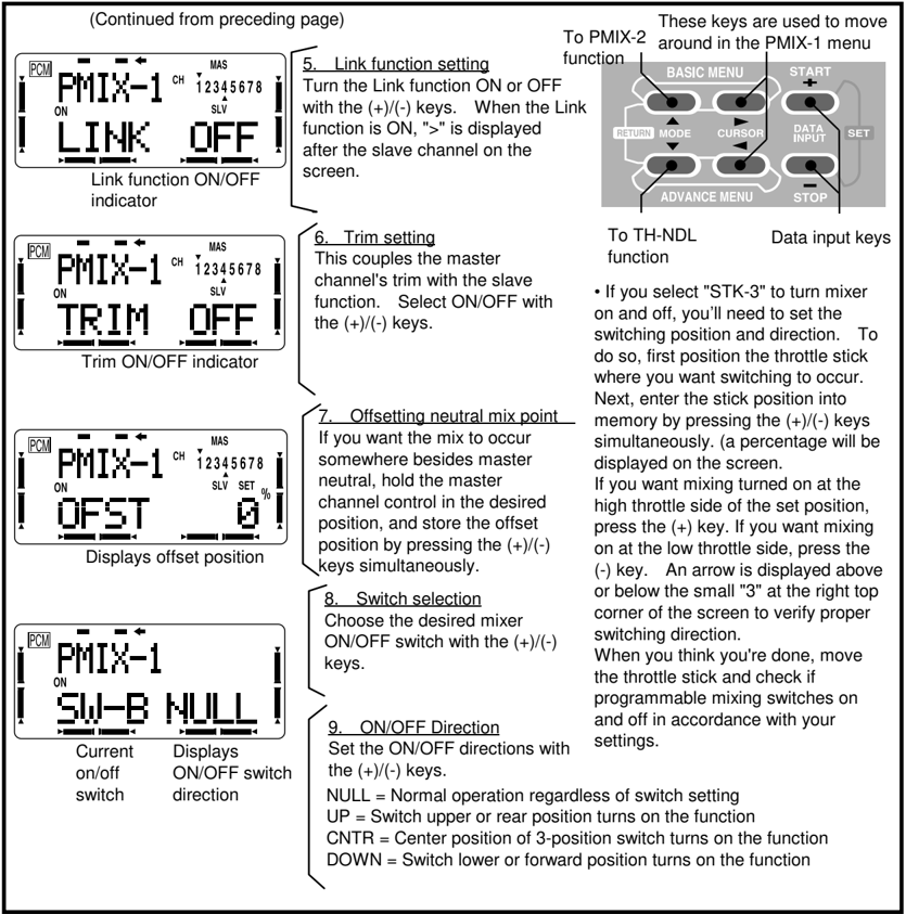
- Link function setting Turn the Link function ON or OFF with the (+)/(-) keys. When the Link function is ON, ">" is displayed after the slave channel on the screen.
Trim ON/OFF indicator
- Trim setting This couples the master channel's trim with the slave function. Select ON/OFF with the (+)/(-) keys.
Displays offset position
- Offsetting neutral mix point If you want the mix to occur somewhere besides master neutral, hold the master channel control in the desired position, and store the offset position by pressing the (+)/(-) keys simultaneously.
Current on/off switch Displays ON/OFF switch direction
-
Switch selection Choose the desired mixer ON/OFF switch with the (+)/(-) keys.
-
ON/OFF Direction Set the ON/OFF directions with the (+)/(-) keys. NULL = Normal operation regardless of switch setting UP = Switch upper or rear position turns on the function CNTR = Center position of 3-position switch turns on the function DOWN = Switch lower or forward position turns on the function
To PMIX-2 function These keys are used to move around in the PMIX-1 menu
To TH-NDL function Data input keys
• If you select "STK-3" to turn mixer on and off, you'll need to set the switching position and direction. To do so, first position the throttle stick where you want switching to occur. Next, enter the stick position into memory by pressing the (+)/(-) keys simultaneously. (a percentage will be displayed on the screen. If you want mixing turned on at the high throttle side of the set position, press the (+) key. If you want mixing on at the low throttle side, press the (-) key. An arrow is displayed above or below the small "3" at the right top corner of the screen to verify proper switching direction. When you think you're done, move the throttle stick and check if programmable mixing switches on and off in accordance with your settings.
82
HOV-TH — Hovering Throttle
The Hovering Throttle function may be used to trim the throttle near hover without affecting pitch. Its position can be memorized so that when the model memory is recalled, the original trim is repeated by rotating the knob to its center position.
When the hovering throttle knob is turned clockwise, the engine speed rises and when turned counterclockwise, the engine speed drops. Changes in rotor speed caused by temperature, humidity, or other conditions can be accommodated. When used with the hovering pitch function, more exact trimming is possible.
Working with Hovering Throttle
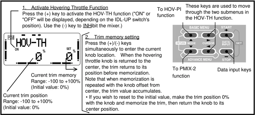
- Activate Hovering Throttle Function Press the (+) key to activate the HOV-TH function ("ON" or "OFF" will be displayed, depending on the IDL-UP switch's position). Use the (-) key to INHibit the mixer.)
To HOV-PI function
These keys are used to move through the two submenus in the HOV-TH function.
- Trim memory setting Press the (+)/(-) keys simultaneously to enter the current knob location. When the hovering throttle knob is returned to the center, the trim returns to its position before memorization. Note that when memorization is repeated with the knob offset from center, the trim value accumulates. • If you wish to reset to the initial value, make the trim position 0% with the knob and memorize the trim, then return the knob to its center position.
Current trim memory Range: -100 to +100% (Initial value: 0%)
Current trim position Range: -100 to +100% (Initial value: 0%)
To PMIX-2 function
Data input keys
HOV-PI — Hovering Pitch
The Hovering Pitch function may be used to trim the rotor pitch near hover without affecting throttle. Its position can be memorized so that when the model memory is recalled, the original trim is repeated by rotating the knob to its center position.
When the hovering pitch knob is turned clockwise, the rotor pitch increases, and when turned counterclockwise, the rotor pitch decreases. Changes in rotor speed caused by temperature, humidity, or other conditions can be accommodated. When used with the hovering throttle function, more exact trimming is possible.
Using the Hovering Pitch Function
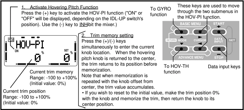
- Activate Hovering Pitch Function Press the (+) key to activate the HOV-PI function ("ON" or "OFF" will be displayed, depending on the IDL-UP switch's position). Use the (-) key to INHibit the mixer.)
To GYRO function
These keys are used to move through the two submenus in the HOV-PI function.
- Trim memory setting Press the (+)/(-) keys simultaneously to enter the current knob location. When the hovering pitch knob is returned to the center, the trim returns to its position before memorization. Note that when memorization is repeated with the knob offset from center, the trim value accumulates. • If you wish to reset to the initial value, make the trim position 0% with the knob and memorize the trim, then return the knob to its center position.
Current trim memory Range: -100 to +100% (Initial value: 0%)
Current trim position Range: -100 to +100% (Initial value: 0%)
To HOV-TH function
Data input keys
83
GYRO — Gyro mixing
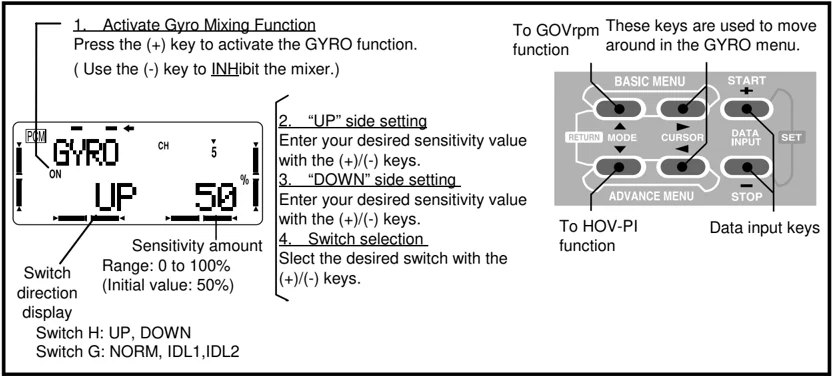
The gyro mixing function is used to adjust the gyro sensitivity from the transmitter. Use this function by connecting the gyro sensitivity adjustment input connector to the channel 5 output of the receiver. Switch H or switch G (idle-up switch) can be selected, and each direction of the changeover switch can be adjusted.
Switch H: The UP and DOWN sides sensitivity can be adjusted.
Switch G: The NORM, IDL1, and IDL2 sensitivities can be adjusted.
Entering Gyro Sensitivity Values
To GOVrpm function
These keys are used to move around in the GYRO menu.
To HOV-PI function
Data input keys
GOVrpm — Governor mixing
The Governor mixing function is used to adjust the GV-1 (Governor) speed settings (rS1, rS2, rS3) from the transmitter. Whether speed switching and governor ON/OFF are switched using one switch or ON/OFF switching is performed using an independent switch can also be selected. When speed setting control uses CH7 and an ON/OFF switch is used, CH8 can also be used.
When speed and ON/OF are switched using one switch (Setting example)
-
For instance, rS3 is adjusted by setting the maximum speed used and lowering it from the transmitter.
-
For the time being, use the initial rate setting above.
-
Since speed adjustment from the transmitter is rate setting, for the actual speed, checking the governor side display and remembering its relationship with the actual speed is convenient.
When governor ON/OFF is controlled using switch B
When governor ON/OFF uses an independent switch, the speed can be adjusted and switched using each position (3 points) of switch C or G.
Caution: The relationship of the governor speed setting rS1~rS3 and the switch positions conforms to the table above. Since the governor mixing function may not be used or the direction may be different, if this mixing was turned ON, first check the direction. At throttle hold, always check that the governor is OFF. Conversely, when the speed value rises, reverse it as described in "Throttle hold OFF direction selection".
Setting the Governor Mixing Function
- Activate Governor Mixing Function Press the (+) key to activate the GOVrpm function. ( Use the (-) key to INHibit the mixer.)
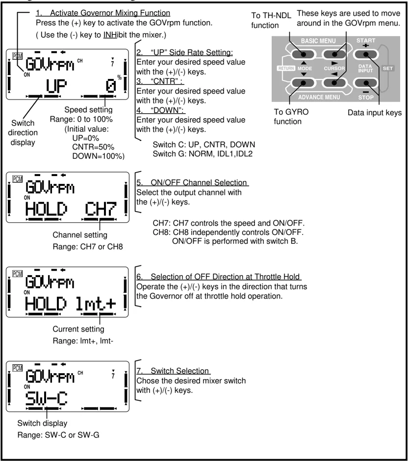
To TH-NDL function These keys are used to move around in the GOVrpm menu.
To GYRO function Data input keys
- “UP” Side Rate Setting: Enter your desired speed value with the (+)/(-) keys.
- “CNTR”: Enter your desired speed value with the (+)/(-) keys.
- “DOWN”: Enter your desired speed value with the (+)/(-) keys.
Switch C: UP, CNTR, DOWN Switch G: NORM, IDL1,IDL2
- ON/OFF Channel Selection Select the output channel with the (+)/(-) keys.
CH7: CH7 controls the speed and ON/OFF. CH8: CH8 independently controls ON/OFF. ON/OFF is performed with switch B.
-
Selection of OFF Direction at Throttle Hold Operate the (+)/(-) keys in the direction that turns the Governor off at throttle hold operation.
-
Switch Selection Chose the desired mixer switch with (+)/(-) keys.
85
TH→NDL — Throttle→Needle Mixing (Normal, Idle)
The Throttle→Needle mixing function is used to control the engine’s mixture using a 5-point curve relative to throttle stick movement. The engine must be equipped with a mixture control system, such as needle control or some other mixture adjustment, and the needle servo must be plugged into CH8. The CH8 knob may be used for High-side mixture adjustment when the idle-up (IDLE) function is ON.
You can have independent control of throttle→needle mixing in both the Normal (NORM) and idle-up (IDLE) conditions. The TH→NDL function includes an ‘acceleration’ function that precedes rapid throttle opening and provides the engine with the best mixture.
Setting Throttle→Needle Mixing
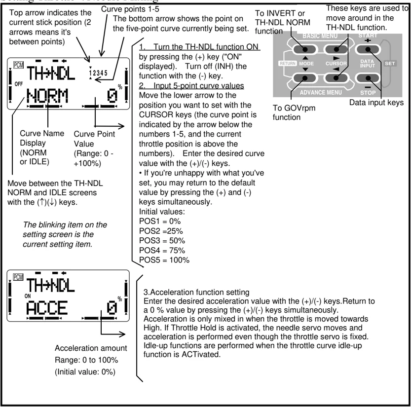
Top arrow indicates the current stick position (2 arrows means it's between points)
Curve points 1-5 The bottom arrow shows the point on the five-point curve currently being set.
To INVERT or TH-NDL NORM function
These keys are used to move around in the TH-NDL function.
PCM TH→NDL OFF NORM 12345 0%
Curve Name Display (NORM or IDLE) Curve Point Value (Range: 0 - +100%)
Move between the TH-NDL NORM and IDLE screens with the (↑)(↓) keys.
The blinking item on the setting screen is the current setting item.
- Turn the TH-NDL function ON by pressing the (+) key ("ON" displayed). Turn off (INH) the function with the (-) key.
- Input 5-point curve values Move the lower arrow to the position you want to set with the CURSOR keys (the curve point is indicated by the arrow below the numbers 1-5, and the current throttle position is above the numbers). Enter the desired curve value with the (+)/(-) keys. • If you're unhappy with what you've set, you may return to the default value by pressing the (+) and (-) keys simultaneously. Initial values: POS1 = 0% POS2 =25% POS3 = 50% POS4 = 75% POS5 = 100%
To GOVrpm function Data input keys
PCM TH→NDL ON ACCE 0%
Acceleration amount Range: 0 to 100% (Initial value: 0%)
- Acceleration function setting Enter the desired acceleration value with the (+)/(-) keys.Return to a 0 % value by pressing the (+)/(-) keys simultaneously. Acceleration is only mixed in when the throttle is moved towards High. If Throttle Hold is activated, the needle servo moves and acceleration is performed even though the throttle servo is fixed. Idle-up functions are performed when the throttle curve idle-up function is ACTivated.
86
INVERT CROSS — Inverted Cross Position
The inverted cross position function sets the point at which low-side pitch is crossed when switching between forward and inverted. It is commonly set to a value of 30%.
Entering Inverted Cross Position
-
Activate Invert Cross Function Press the (+) key to activate the INVERT CRSS function ("ON" or "OFF" will be displayed, depending on the Invert switch H's position). Use the (-) key to INHibit the mixer.)
-
Cross point setting Enter your desired cross point value with the (+)/(-) keys. You may return to the initial value of 30% by pressing the (+)/(-) keys simultaneously.
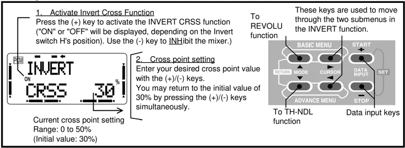
Current cross point setting Range: 0 to 50% (Initial value: 30%)
To REVOLU function These keys are used to move through the two submenus in the INVERT function.
To TH-NDL function Data input keys
REVOLU — Revolution Mixing (Normal, Idle-Up 1, Idle-Up 2)
Revolution mixing is used to mix pitch→rudder to suppress the torque reaction generated by changes in the pitch and speed of the main rotor. The mixing ratio can be set by a five-point curve.
Three are three kinds of revolution mixing: normal (NORM), idle-up 1 (IDL1), and idle-up 2 (IDL2). Only basic NORM revolution mixing is displayed in the Basic Menu, but all the revolution curves are visible in the Advance Menu. If you program the normal curve in the Basic Menu, the same curve is automatically reflected in the REVOLU NORM menu within the Advance Menu, and vice versa.
The REVOLU functions for the IDL1 and IDL2 curves will not operate until the OFST-1 and OFST-2 functions are activated.
Revolution Mixing for Idle-Up 1&2
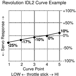
These two functions set the mixing rate so that the fuselage direction is straight ahead during high-speed flight. You can set either a curve or offset position to match the helicopter's tendencies. You may also program in reverse rudder mixing for 3D flight.
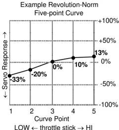
Example Revolution-Norm Five-point Curve
87
Revolution IDL1 Curve Example
Curve Point LOW \leftarrow throttle stick \rightarrow HI
Revolution IDL2 Curve Example
Curve Point LOW \leftarrow throttle stick \rightarrow HI
Inputting Revolution Five-Point Curves
The Revolution Normal function is on at startup. It can be turned ON/OFF with the (+)/(-) keys.
Top arrow indicates the current stick position (2 arrows means it's between points)
Curve points 1-5
The blinking item on the setting screen is the current setting item.
The bottom arrow shows the point on the five-point curve currently being set.
To PI-CRV function
These keys are used to move through the five submenus in the REVOLU function.
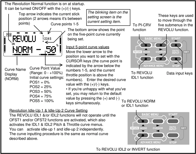
Curve Name Display (NORM)
Curve Point Value (Range: 0 - +100%) Initial curve settings: POS1 = 0% POS2 = 25% POS3 = 50% POS4 = 75% POS5 = 100%
Input 5-point curve values Move the lower arrow to the position you want to set with the CURSOR keys (the curve point is indicated by the arrow below the numbers 1-5, and the current throttle position is above the numbers). Enter the desired curve value with the (+)/(-) keys. • If you're unhappy with what you've set, you may return to the default value by pressing the (+) and (-) keys simultaneously.
To REVOLU IDL1 function
Data input keys
To REVOLU NORM or IDL1 function
Revolution Idle-Up 1 & Idle-Up 2 Curve Setting The REVOLU IDL1 &/or IDL2 functions will not operate until the OFST1 and/or OFST2 functions are activated, which also activates the IDL1 & IDL2 Pitch & Throttle curve menus. You can activate idle-up 1 and idle-up 2 independently. The curve inputting procedure is the same as normal curve described above.
To REVOLU IDL2 or INVERT function
88
PI-CRV — Pitch Curve (Normal, Idle-Up1 & 2, Hold, Inverted)
The pitch curve is defined by a 5-point curve so that you may set the best pitch motion relative to throttle stick movement. Each point on the curve can be adjusted over a 0% to 100% range.
The T8U system contains five pitch curves: normal (NORM), idle-up 1 (IDL1), idle-up 2 (IDL2), hold (HOLD), and inverted (INVR). The basic normal pitch curve is the only one displayed in the Basic Menu, but all of the pitch curves can be viewed in the Advance menu. The Normal curve is exactly the same in both the Advance and Basic Menus.
Use the idle-up switch (switch G) to move between Normal, idle-up 1, and idle-up 2. (The PI-CURV functions for IDL1 and IDL2 curves will not operate until the OFST-1 and OFST-2 functions are activated.) Switching to the hold (HOLD) function is performed with switch E. Switching to the inverted (INVR) function is performed with switch H. Note that whenever the hold switch is turned on, it has priority regardless of the idle-up switch position.
Normal Curve Adjustment
The normal (NORM) pitch curve function produces the basic pitch curve for flight near hover. It is set up to provide up and down control at a constant engine speed along with the normal throttle curve.
Idle-Up 1 & Idle-Up 2 Curve Adjustment
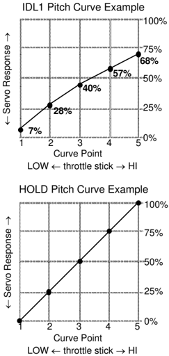
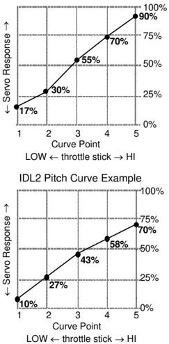
The HI-side pitch curve limits the maximum rotor pitch so that a large load is not applied to the engine. The LO-side pitch curve produces a curve with a minimum pitch of -4°. Idle-up 1 is used for 540° stall turns, looping, and rolling stall turns, while idle-up 2 is used for rolls.
Throttle-Hold Curve Adjustment
The throttle hold curve is used when performing autorotations, and should provide pitch from -4° to +12°. To get this pitch range, set the HI and LO rates to +100% and -100% respectively.
Examples of these four curves are shown below:
89
SETTING METHOD
The Pitch Curve Normal function is on at startup.
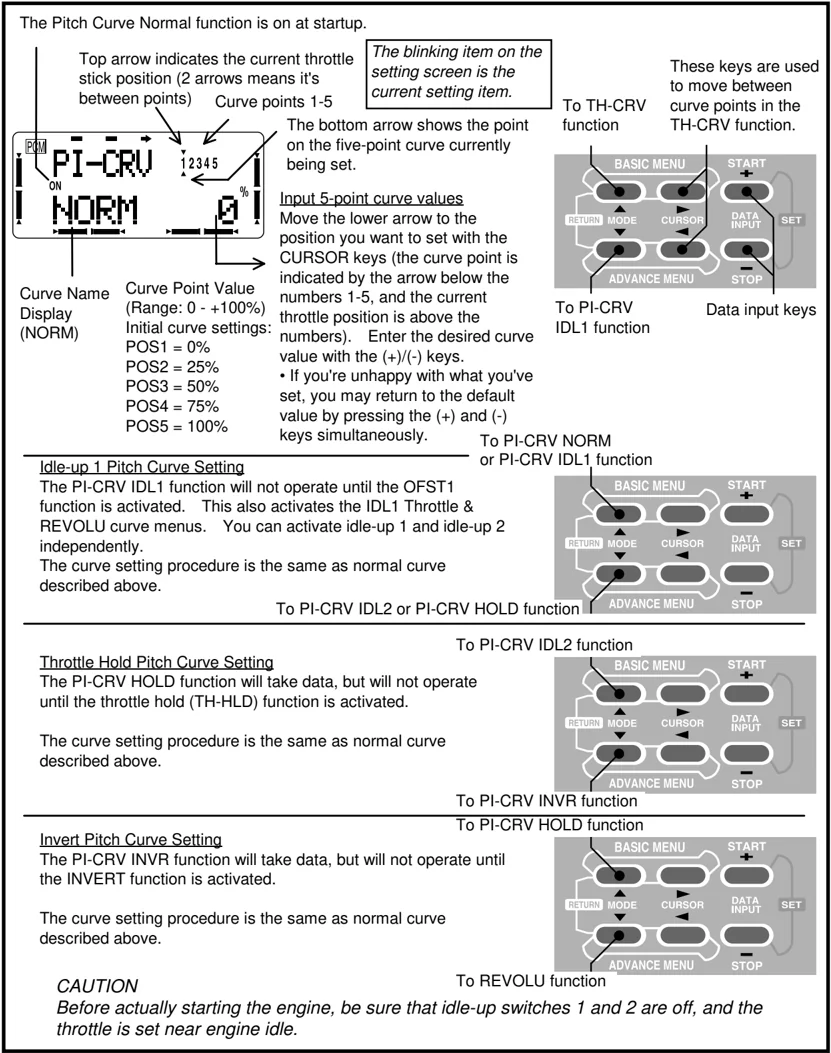
Top arrow indicates the current throttle stick position (2 arrows means it's between points) Curve points 1-5 The bottom arrow shows the point on the five-point curve currently being set.
The blinking item on the setting screen is the current setting item.
These keys are used to move between curve points in the TH-CRV function.
To TH-CRV function
Curve Name Display (NORM) Curve Point Value (Range: 0 - +100%) Initial curve settings: POS1 = 0% POS2 = 25% POS3 = 50% POS4 = 75% POS5 = 100%
Input 5-point curve values Move the lower arrow to the position you want to set with the CURSOR keys (the curve point is indicated by the arrow below the numbers 1-5, and the current throttle position is above the numbers). Enter the desired curve value with the (+)/(-) keys. • If you're unhappy with what you've set, you may return to the default value by pressing the (+) and (-) keys simultaneously.
To PI-CRV IDL1 function Data input keys
Idle-up 1 Pitch Curve Setting
The PI-CRV IDL1 function will not operate until the OFST1 function is activated. This also activates the IDL1 Throttle & REVOLU curve menus. You can activate idle-up 1 and idle-up 2 independently. The curve setting procedure is the same as normal curve described above.
To PI-CRV NORM or PI-CRV IDL1 function
To PI-CRV IDL2 or PI-CRV HOLD function
Throttle Hold Pitch Curve Setting
The PI-CRV HOLD function will take data, but will not operate until the throttle hold (TH-HLD) function is activated. The curve setting procedure is the same as normal curve described above.
To PI-CRV IDL2 function
To PI-CRV INVR function
Invert Pitch Curve Setting
The PI-CRV INVR function will take data, but will not operate until the INVERT function is activated. The curve setting procedure is the same as normal curve described above.
To PI-CRV HOLD function
To REVOLU function
CAUTION Before actually starting the engine, be sure that idle-up switches 1 and 2 are off, and the throttle is set near engine idle.
90
Handling the CAMPac
The setting data for 8 models can be saved in the T8UAPS transmitter itself and the setting data for 8 more models can be saved in the DP-16K CAMPac (Option) removable memory module.
CAMPac initialization
To use the CAMPac with the T8UAPS, the CAMPac must be initialized when the power is turned on for the first time. After the message "INIT? EXT-MEM" appears on the screen when the power is turned on, press the "+" key. This automatically initializes the storage area for 8 models. Further operation is unnecessary.
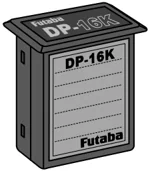
DP-16K CAMPac (Option) When using the DP-16K CAMPac, remove the transmitter dust cap and insert the data pack as far as it will go. Always turn off the transmitter power before inserting or removing the data pack.
Compatibility of 8Usuper Series and old 8U Series transmitter data packs The data memorized in the data pack using an old 8U Series can be copied to the memory in the body of the 8Usuper Series transmitter. When old data is copied, initialization data for the new functions added with the 8Usuper are added.
(1) Call the copy function in the BASIC menu/MODEL submenu. (Call the "Pac" screen following "COPY" of the function name display at the top left of the screen.) (2) Select the model No. you want to copy using the + or - key. (3) Press the + and - keys simultaneously two times. (The data is copied to transmitter side model No. 8.)
However, when data saved for mixing type "H-2" for helicopters using an old model was copied to the T8UAPS transmitter, whereas the aileron and pitch travel in the old setting data is fixed at 60%, both the aileron and pitch initial value settings of the new function (swash AFR function) of the T8UAPS is 50%. Therefore, the travel is reduced by that amount. Readjust after copying the setting data.
All the data memorized in the CAMPac using an old 8U Series can be batch converted to 8USUPER Series transmitter data. However, the converted CAMPac cannot be used with an old 8U Series transmitter.
(1) While pressing the two BASIC menu keys simultaneously, turn on the transmitter power switch. (The conversion function screen is called.) (2) Press the + key. (Conversion is started and all the models data in the data pack are converted.)
The data memorized in the data pack using the 8USUPER Series cannot be used with the old 8U Series.
Back-up unnecessary The setting data (transmitter body and CAMPac) are memorized in memory elements that do not require a back-up battery. Therefore, the data can be used while ignoring the back-up battery life. Of course, the setting data is not destroyed even when the transmitter battery is replaced.
GLOSSARY
The abbreviations used with the 8UA are defined below alphabetically. Related pages are given in parenthesis following the definition ().
A
AB, ABK, ABRAKE Airbrake function (47) ACCE Acceleration function used with special carburetor. (51) ACRO Acrobatic aircraft menu (26–51) ACT Active: Function will operate if switched on AI, AIL Aileron AI-DIF Aileron differential function creates different up & down travel. (46) AIL→FL Aileron→flap mixing used by gliders to increase roll rate. (61) AIL2 Second aileron output channel switching (34) ALL All ALVATR Ailevator function produces differential elevator movement. (49) ATL Adjustable Travel Limit. Limits throttle trims to only the throttle idle position. (31) ATV Adjustable Travel Volume. Function that adjusts the servo travel at the left and right sides. (26)
B
BFLY Butterfly mixing for gliders (sometimes called "crow" (59)
C
C/DN Center & down position of switch. camber see FLPTRM CH5 Channel 5. CH6 Channel 6. CH7 Channel 7. CH8 Channel 8. CNTR Center. Center position of switch. COPY Data copy: command used to copy one memory to another (36) crow see BFLY CRSS Cross position. Low side pitch crossing point when inverted flight using a stick is used. (87)
D
D/R Dual rate: switch-controlled travel function. (26) DATARSET Data reset: clear model memory (31) DELAY Delay circuit (51,80) DISP Trim display method. (39) DOWN Lower position.
E
EG/S Engine starter. Engine data switch function. (32) EL, ELE Elevator. CH2 ELE→FL Elevator → Flap mixing (48) ELEVON Elevon: function that combines the ailerons and elevators for tailless models. (49) ERROR Error generation. (16) ERRORBACKUP Backup error. All the programming was lost. When displayed, return transmitter for repair. (16) ERRORLOWBATT Low battery warning. The battery voltage is unsafe. (16) ERRORMDLSEL Model selection error. Data pack error display. (16) EXP Exponential. Nonlinear servo response to stick . (28) EXT-MEM External memory (data pack). (16)
F
F/S Fail safe function moves servos to preset positions when interference occurs. (29) FL, FLP Flap. CH6 FLP→A Flap→aileron mixing used by gliders for camber control. (60) FLPRON Flaperon function gives the ailerons a flap function. (45) FLPTRM Flap trim function; controls camber on gliders (46) FREE Safety mechanism switch not set.
G
GE, GEAR Gear. Usually plugged into CH5 GLID1FLP Menu for glider with 1 flap servo. (52, 53) GLID2FLP Menu for glider with 2 flap servos. (52, 53) GOVrpm Governor mixing function. (84) GY, GYR Gyro. Usually plugged into CH5 GYRO Gyro mixing function. (84)
H
HELISWH1 Helicopter swash type 1 menu. (65) HELISWH2 Helicopter swash type 2 menu. (65) HLDP Hold position. Throttle fixed position at throttle hold. (79) HOLD Throttle hold position when autorotation performed. (79) HOV-PI Hovering pitch. Pitch trim function near hovering. (83) HOV-TH Hovering throttle. Throttle trim function near hovering. (83)
I
IDL-1 Idle-up. 1: use for loops, 540ø stall turns, and other maneuvers by helicopters IDL-2 Idle-up 2: use for rolls and other aerobatics by helicopters. IDL-DN Idle down function lowers engine idling speed with a switch. (29) INH Inhibit. Function will not operate
92
- INIT ........ Initialize. External memory initialization. (16)
- INVERT, INVR ........ Inverted flight. (74)
L
- L/D ........ Left/down. Snap roll direction switching. (50)
- L/U ........ Left/up. Snap roll direction switching. (50)
- LIN ........ Linear. Method of performing mixing by throttle stick. (47)
- LINK ........ Link. Programmable mixing function. (43, 81)
- LOCK ........ Lock. Function locked off.
M
- MANU ........ Manual. Operation by switch.
- MOD ........ Modulation: PCM or PPM (35)
- MODEL ........ Model function (36)
N
- NAME ........ Model name. (37)
- NEGA ........ Negative. Screen trim display by reversing black and white. (39)
- NEXT< > ........ There are additional screens.
- NORM ........ Normal. Hovering flight and other normal flight settings.
- NULL ........ Function is always on, no switching
O
- OFF ........ Function off. Switch off.
- OFST-1 ........ Offset-1. Trim offset by switch. (80)
- OFST-2 ........ Offset-2. Trim offset by switch. (80)
- OK? ........ Confirm before action taken.
- ON ........ Function or Switch in ON position.
P
- PARA ........ Parameter function. (31)
- PCM ........ Pulse Code Modulation. (34)
- PI, PIT ........ Pitch control, usually plugged in CH6
- PI-CRV ........ Pitch curve. Curve that specifies pitch servo movement by 5 different point locations. (71, 89)
- PMIX ........ Programmable mixing. Mixing between arbitrary channels. (43, 81)
- POS ........ Position.
- POSI ........ Positive. Screen trim displayed by black lines on a white background. (40)
- PPM ........ Pulse Position Modulation, also known as FM (35)
R
- R/D ........ Right down. Snap roll direction switching. (50)
- R/U ........ Right up. Snap roll direction switching. (50)
- REVERS, REV ........ Reverse. Servo operating direction switching function. (30)
- REVOLU ........ Revolution. Mixing function that cancels the main rotor torque reaction. (72, 87)
- RU, RUD ........ Rudder. CH4.
S
- SAFE ........ Safety switch to prevent unwanted actions, like snap rolls. (50)
- SEL ........ Select a model number. (36)
- SET ........ Used to..set..or enter a stick or knob position.
- SNAP, SNP ........ Snap roll. Switch turns on function that performs snap rolls. (50)
- SPEED ........ Speed presets for gliders. (63)
- START ........ Start (launch) presets for gliders. (62)
- STEP ........ Trim step rate; rate at which trim moves when trim held on. (38)
- STICK, STK ........ Stick.
- STK-3 ........ Throttle stick switches on/off
- SUBTRM ........ Subtrim function used to adjust servo neutrals. (39)
- SW-X ........ Switch #X.
- SWASH ........ Swash AFR function. (73)
T
- TH, THR ........ Throttle. CH3.
- TH-CRV ........ Throttle curve. Curve that specifies throttle servo movement by five different point locations. (70, 77)
- TH-CUT ........ Throttle cut. Engine stop. (40,75)
- TH-DLY ........ Throttle delay. Function that delays throttle servo operation. (51)
- TH-HLD ........ Throttle hold. Function that holds the throttle in the idling or stop position. (79)
- TH→NDL ........ Throttle→needle. Mixing used by special carburetor. (51, 86)
- TIMER ........ Stopwatch. (40)
- TRAINR ........ Trainer. Trainer function. (35)
- TRIM, TRM ........ Trim function. (38)
- TYPE ........ Model mixing type. (32)
U
- UNLK ........ Unlock.
- UP ........ Up.
V
- V-TAIL ........ V-tail function combines the elevators and rudder. (48)
W
- WAIT ........ Wait.
- WARNING ........ Warning display. (16)
- WARNING AIR-BRAKE ........ Airbrake switch is on.
- WARNING BUTTERFLY ........ Butterfly switch is on.
- WARNING IDLEDOWN ........ Idle-down switch is on.
- WARNING IDLEUP ........ Idle-up switch is on.
- WARNING INVERTED ........ Inverted switch is on.
- WARNING SNAPROLL ........ Snap roll switch is on.
- WARNING THR-CUT ........ Throttle cut switch is on.
- WARNING THR-HOLD ........ Throttle hold switch is on.
- WARNING TRIMOFST ........ Trim offset switch is on.
93
AIRCRAFT (ACRO) DATA SHEET
Make a copy before using
Modulation PCM FM
Model Name ________
Model Type: ACRO
BASIC
| CH 1 | CH 2 | CH 3 | CH 4 | CH 5 | CH 6 | CH 7 | CH 8 | ||
|---|---|---|---|---|---|---|---|---|---|
| ATV | Adjustable Travel Volume | R/U | % | % | % | % | % | % | % |
| L/D | % | % | % | % | % | % | % | ||
| D/R | Dual Rate settings | Up | % | % | % | SW | |||
| Down | % | % | % | AIL: | |||||
| EXP | Exponential settings | Up | % | % | % | ELE: | |||
| Down | % | % | % | RUD: | |||||
| IDL-DN | Idle-Down | ACT | INH | setting | % | SW | SW.DR | ||
| F/S | Failsafe | Norm | |||||||
| F/S | % | % | % | % | % | % | % | ||
| REVERSE | Servo reverse | N-R | N-R | N-R | N-R | N-R | N-R | N-R | |
| ATL | Adj. Travel Limit | ON | OFF | ||||||
| EG/S | Engine Starter | CH | |||||||
| AIL2 | Second aileron | CH | |||||||
| TRAINR | Trainer | ||||||||
| STEP | Trim Step | ||||||||
| DISP | Trim Display | NEGA | POSI | ||||||
| SUBTRM | Subtrims | Value | % | % | % | % | % | % | % |
| TH-CUT | Throttle Cut | ACT | INH | setting | % | SW | SW.DR | ||
| TIMER | Timer Settings | Minute | Second | UP-DN | SW | SW.DR |
ADVANCE
| FLPRON | Flaperon | ACT-INH | CH 1 | L - AIL % | R - AIL % | CH 6 | L - AIL % | R - AIL % | CH 1 % CH 6 % | ||||
| FLPTRM | Flap Trim | ACT-INH | setting % | ||||||||||
| AI-DIFF | Aileron Differential | ACT-INH | CH 1 | L - AIL % | R - AIL % | CH 7 | L - AIL % | R - AIL % | |||||
| ABRAKE | Airbrake | ACT-INH | Amount | AIL % | FLP % | ELE % | Elevator Delay % | ||||||
| ELE-FL | Elev-flap | ACT-INH | UP % | DOWN % | |||||||||
| V-TAIL | V-tail mix | ACT-INH | CH 2 ELE % | CH 4 % | RUD | CH 2 % | CH4 % | ||||||
| ELEVON | Elevon mix | ACT-INH | CH 1 | L - AIL % | R - AIL % | CH 2 | L - AIL % | R - AIL % | CH 1 % CH 2 % | ||||
| ALVATR | Ailevator function | ACT-INH | CH2 AIL % | CH8 % | ELE | CH2 % | CH8 % | ||||||
| SNP | Snap Rolls in four directions | ACT-INH | R/U | AIL % | ELE % | RUD % | |||||||
| On-Off Switch | SW | R/D | AIL % | ELE % | RUD % | ||||||||
| SAFE | L/U | AIL % | ELE % | RUD % | |||||||||
| ON-OFF-FREE | L/D | AIL % | ELE % | RUD % | |||||||||
| TH-DLY | Throttle Delay | ACT-INH | Delay setting | % | |||||||||
| TH-NDL | Throttle-needle mix | ACT-INH | 5-point travel | P1 | P2 | P3 | P4 | P5 | Accel. setting % | ||||
| PMIX-1 | Mixing | ACT-INH | MASTER | CH | SLAVE | CH | Amount % | Link ON-OFF | Trim ON-OFF | Offset % | Switch | SW.DR | |
| PMIX-2 | ACT-INH | MASTER | SLAVE | % | ON-OFF | ON-OFF | % | SW | |||||
| PMIX-3 | ACT-INH | MASTER | SLAVE | % | ON-OFF | ON-OFF | % | SW | |||||
| PMIX-4 | ACT-INH | MASTER | SLAVE | % | ON-OFF | ON-OFF | % | SW | |||||
| PMIX-5 | ACT-INH | MASTER | SLAVE | % | ON-OFF | ON-OFF | % | SW | |||||
| PMIX-6 | ACT-INH | MASTER | SLAVE | P1 | P2 | P3 | P4 | P5 | ON-OFF | SW |
94
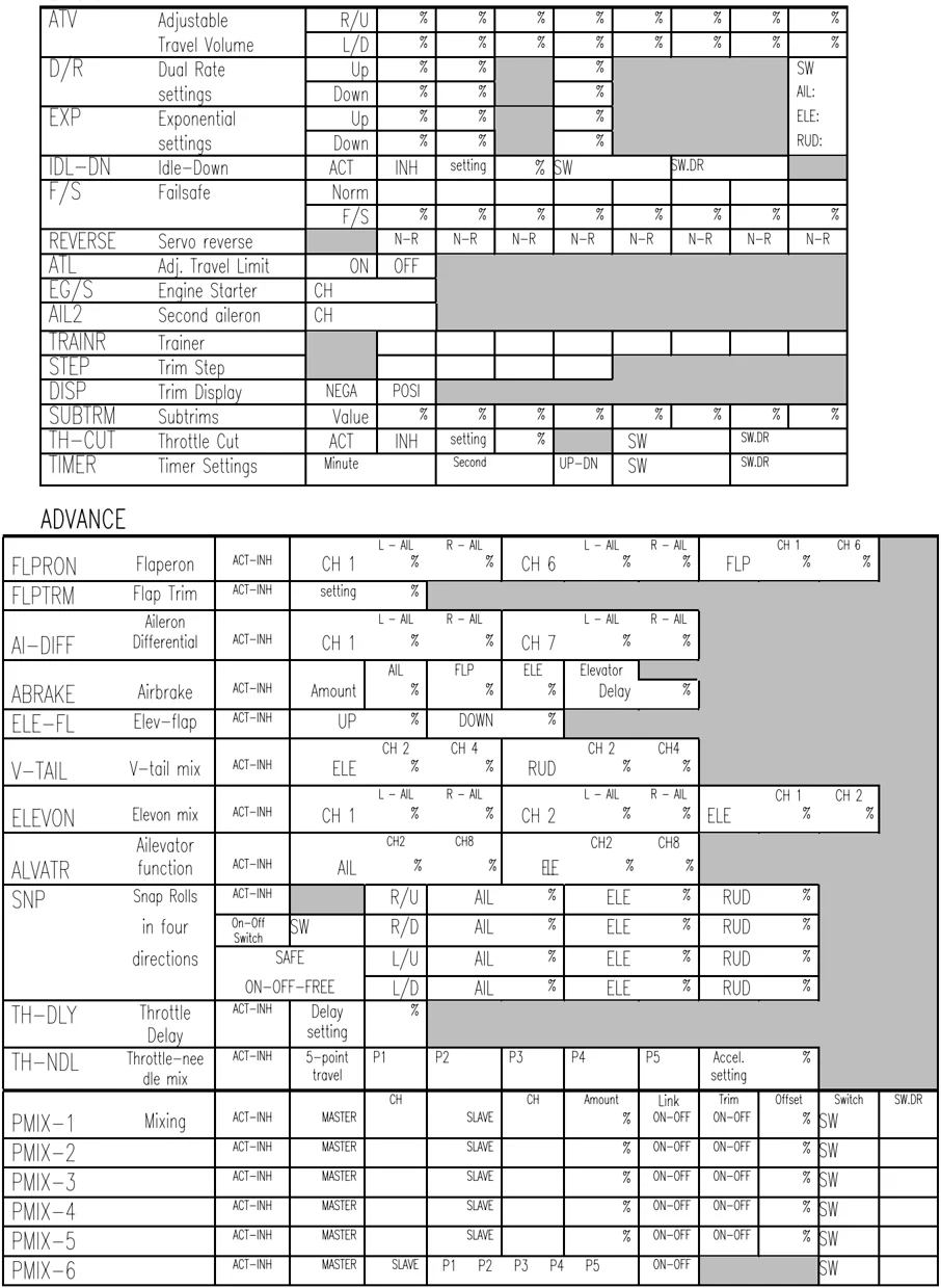
| PMIX-7 | ACT-INH | MASTER | SLAVE | P1 | P2 | P3 | P4 | P5 | ON-OFF | SW |
|---|
95
GLIDER (GLID) DATA SHEET
Make a copy before using
Model Name ________
Model Type: GLID __ FLP
Modulation PCM FM
CH 1 CH 2 CH 3 CH 4 CH 5 CH 6 CH 7 CH 8
BASIC
| ATV | Adjustable Travel Volume | R/U | % | % | % | % | % | % | % | % |
|---|---|---|---|---|---|---|---|---|---|---|
| L/D | % | % | % | % | % | % | % | % | ||
| D/R | Dual Rate settings | Up | % | % | % | SW | ||||
| Down | % | % | % | AIL: | ||||||
| EXP | Exponential settings | Up | % | % | % | ELE: | ||||
| Down | % | % | % | RUD: | ||||||
| IDL-DN | Idle-Down | ACT | INH | setting | % | On-Off Switch | SW | Switch Direction | ||
| F/S | Failsafe | Norm | ||||||||
| F/S | % | % | % | % | % | % | % | % | ||
| REVERSE | Servo reverse | N-R | N-R | N-R | N-R | N-R | N-R | N-R | N-R | |
| ATL | Adj. Travel Limit | ON | OFF | |||||||
| EG/S | Engine Starter | CH | ||||||||
| AIL2 | Second Aileron | CH | ||||||||
| TRAINR | Trainer | |||||||||
| STEP | Trim Step | |||||||||
| DISP | Trim Display | NEGA | POSI | |||||||
| SUBTRM | Subtrims | Value | % | % | % | % | % | % | % | % |
| TH-CUT | Throttle Cut | ACT | INH | setting | % | SW | SW.DR | |||
| TIMER | Timer Settings | Minute | Second | UP-DN | SW | SW.DR |
ADVANCE
| FLPRON | (GLID1F only) Flaperon | ACT-INH | CH 1 | L - AIL % | R - AIL % | CH 6 | L - AIL % | R - AIL % | FLP | CH 1 % | CH 6 % | |
|---|---|---|---|---|---|---|---|---|---|---|---|---|
| FLPTRM | Camber | ACT-INH | INH | setting | % | |||||||
| AI-DIFF | Aileron Differential | ACT-INH | CH 1 | L - AIL % | R - AIL % | CH 7 | L - AIL % | R - AIL % | ||||
| BFLY | Butterfly | ACT-INH | Amount | AIL % | FLP % | ELE % | Elevator Delay % | start pt. % | ||||
| FLP-AI | (GLID2F only) Flap-ail mix | ACT-INH | Amount | % | Newtral Offset % | % | Switch SW | SW.DR | ||||
| AIL-FL | (GLID2F only) Ail-flap mix | ACT-INH | Amount | L - AIL % | R - AIL % | Switch SW | SW.DR | |||||
| ELE-FL | Elev-flap | ACT-INH | UP % | DOWN % | ||||||||
| V-TAIL | V-tail mix | ACT-INH | ELE | CH 2 % | CH 4 % | RUD | CH 2 % | CH4 % | ||||
| ELEVON | (GLID1F only) Elevon mix | ACT-INH | CH 1 | L - AIL % | R - AIL % | CH 2 | L - AIL % | R - AIL % | ELE | CH 1 % | CH 2 % | |
| START | Launch presets | ACT-INH | Amount | AIL 1 % | ELE % | FLP 1 % | FLP 2 % | AIL 2 % | ||||
| SPEED | Seed presets | ACT-INH | Amount | AIL 1 % | ELE % | FLP 1 % | FLP 2 % | AIL 2 % | ||||
| PMIX-1 | Programmable Mixing Mixer #1 | ACT-INH | MASTER | CH | SLAVE | CH | Amount % | Link ON-OFF | Trim ON-OFF | Offset % | Switch SW | SW.DR |
| PMIX-2 | Mixer #2 | ACT-INH | MASTER | SLAVE | % | ON-OFF | ON-OFF | % | SW | |||
| PMIX-3 | Mixer #3 | ACT-INH | MASTER | SLAVE | % | ON-OFF | ON-OFF | % | SW | |||
| PMIX-4 | Mixer #4 | ACT-INH | MASTER | SLAVE | % | ON-OFF | ON-OFF | % | SW | |||
| PMIX-5 | Mixer #5 | ACT-INH | MASTER | SLAVE | % | ON-OFF | ON-OFF | % | SW | |||
| PMIX-6 | Mixer #6 | ACT-INH | MASTER | SLAVE | P1 P2 P3 P4 P5 | ON-OFF | SW | |||||
| PMIX-7 | Mixer #7 | ACT-INH | MASTER | SLAVE | P1 P2 P3 P4 P5 | ON-OFF | SW |
96
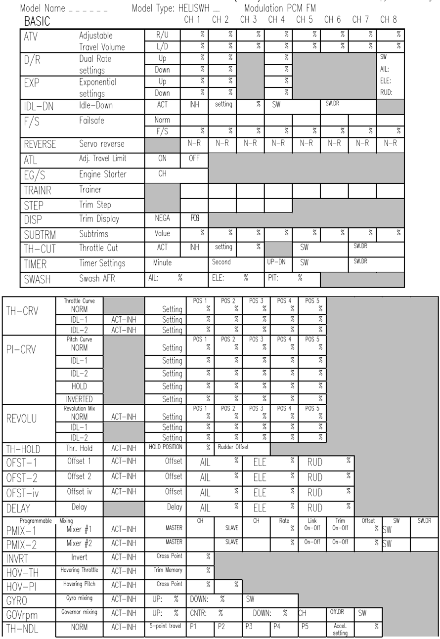
HELICOPTER (HELI) DATA SHEET
Make a copy before using
Model Name ________ Model Type: HELISWH ___ Modulation PCM FM
BASIC
| ATV | Adjustable Travel Volume | R/U | % | % | % | % | % | % | % | % |
|---|---|---|---|---|---|---|---|---|---|---|
| L/D | % | % | % | % | % | % | % | % | ||
| D/R | Dual Rate settings | Up | % | % | % | SW | ||||
| Down | % | % | % | AIL: | ||||||
| EXP | Exponential settings | Up | % | % | % | ELE: | ||||
| Down | % | % | % | RUD: | ||||||
| IDL-DN | Idle-Down | ACT | INH | setting | % | SW | SW.DR | |||
| F/S | Failsafe | Norm | ||||||||
| F/S | % | % | % | % | % | % | % | % | ||
| REVERSE | Servo reverse | N-R | N-R | N-R | N-R | N-R | N-R | N-R | N-R | |
| ATL | Adj. Travel Limit | ON | OFF | |||||||
| EG/S | Engine Starter | CH | ||||||||
| TRAINR | Trainer | |||||||||
| STEP | Trim Step | |||||||||
| DISP | Trim Display | NEGA | POS | |||||||
| SUBTRM | Subtrims | Value | % | % | % | % | % | % | % | % |
| TH-CUT | Throttle Cut | ACT | INH | setting | % | SW | SW.DR | |||
| TIMER | Timer Settings | Minute | Second | UP-DN | SW | SW.DR | ||||
| SWASH | Swash AFR | AIL: % | ELE: % | PIT: % |
| TH-CRV | Throttle Curve NORM | Setting | POS 1 % | POS 2 % | POS 3 % | POS 4 % | POS 5 % | |||||
|---|---|---|---|---|---|---|---|---|---|---|---|---|
| IDL-1 | ACT-INH | Setting | % | % | % | % | % | |||||
| IDL-2 | ACT-INH | Setting | % | % | % | % | % | |||||
| PI-CRV | Pitch Curve NORM | Setting | POS 1 % | POS 2 % | POS 3 % | POS 4 % | POS 5 % | |||||
| IDL-1 | Setting | % | % | % | % | % | ||||||
| IDL-2 | Setting | % | % | % | % | % | ||||||
| HOLD | Setting | % | % | % | % | % | ||||||
| INVERTED | Setting | % | % | % | % | % | ||||||
| REVOLU | Revolution Mix NORM | ACT-INH | Setting | POS 1 % | POS 2 % | POS 3 % | POS 4 % | POS 5 % | ||||
| IDL-1 | Setting | % | % | % | % | % | ||||||
| IDL-2 | Setting | % | % | % | % | % | ||||||
| TH-HOLD | Thr. Hold | ACT-INH | HOLD POSITION | % | Rudder Offset | |||||||
| OFST-1 | Offset 1 | ACT-INH | Offset | AIL % | ELE % | RUD % | ||||||
| OFST-2 | Offset 2 | ACT-INH | Offset | AIL % | ELE % | RUD % | ||||||
| OFST-iv | Offset iv | ACT-INH | Offset | AIL % | ELE % | RUD % | ||||||
| DELAY | Delay | Delay | AIL % | ELE % | RUD % | |||||||
| PMIX-1 | Programmable Mixing Mixer #1 | ACT-INH | MASTER | CH | SLAVE | CH | Rate % | Link On-Off | Trim On-Off | Offset % | SW | SW.DR |
| PMIX-2 | Mixer #2 | ACT-INH | MASTER | SLAVE | % | On-Off | On-Off | % | SW | |||
| INVRT | Invert | ACT-INH | Cross Point | % | ||||||||
| HOV-TH | Hovering Throttle | ACT-INH | Trim Memory | % | ||||||||
| HOV-PI | Hovering Pitch | ACT-INH | Cross Point | % | % | |||||||
| GYRO | Gyro mixing | ACT-INH | UP: % | DOWN: % | SW | |||||||
| GOVrpm | Governor mixing | ACT-INH | UP: % | CNTR: % | DOWN: % | CH | Off.DR | SW | ||||
| TH-NDL | NORM | ACT-INH | 5-point travel | P1 | P2 | P3 | P4 | P5 | Accel. setting | % |
97
Throttle-needle mix | IDL-1 | ACT-INH | 5-point travel | P1 | P2 | P3 | P4 | P5 | Accel. setting | %
98
REPAIR SERVICE
Before you decide to have your system repaired, if there is no apparent physical damage, read this instruction manual again and check to be sure that you are operating the system as it is supposed to be operated. If you are still having trouble, pack up your system in its original shipping materials and send it to your nearest authorized Futaba R/C Service Center.
Be sure to include a note in your package that describes the trouble in as much detail as possible, including:
- Symptoms of the problem, any unusual mounting conditions
- A list of items you are sending, and what you want to be repaired.
- Your name, address, and telephone number.
- When requesting warranty repair, please include the warranty card.
Read the warranty card supplied with your system
If you have any questions regarding this product, please consult Futaba. The address and telephone numbers of our service center is given below. Telephone inquiries are accepted from 9:00 AM to 5:00 PM weekdays, except on holidays.
Futaba Corporation of America P. O. Box 19767, 4 Studebaker Irvine CA 92613-9767
Telephone: 1-949-455-9888 FAX 1-949-455-9899
99