© MULTIPLEX modelltechnik gmbh • Neuer Weg 15 • D-75223 NIEFERN • Germany Imprimé en Allemagne • Sous réserve d'erreur d'impression, de modification et de disponibilité. Handbuch PROFI mc 3030 französisch Best.-Nr./réf. 85 9955
Manual
for the
PROFI mc 3030

MULTIPLEX Modelltechnik GmbH ● Neuer Weg 15 ● D-75223 Niefern ● Germany © MULTIPLEX 1998, Printed in Germany Errors and omissions excepted. We reserve the right to alter conditions of supply! GB # 85 9962

NOTE: Please add 3 to the page numbers in the index to find the corresponding PDF file page number.
Contents
\begin{tabular}{p{0.55\textwidth} r p{0.55\textwidth} r} \multicolumn{2}{l}{\textbf{Page}} & \multicolumn{2}{r}{\textbf{Page}} \ \textbf{Introduction} & & \textbf{Adjusting the transmitter controls} & \
- Welcome to the PROFI mc 3030 \ldots \ldots \ldots \ldots \ldots \ldots \ldots \ldots \ldots \ldots \ldots \ldots \ldots \ldots \ldots \ldots \ldots \ldots \ldots \ldots \ldots \ldots \ldots \ldots \ldots \ldots \ldots \ldots \ldots \ldots \ldots \ldots \ldots \ldots \ldots \ldots \ldots \ldots \ldots \ldots \ldots \ldots \ldots \ldots \ldots \ldots \ldots \ldots \ldots \ldots \ldots \ldots \ldots \ldots \ldots ........ & 1 & An important difference \ldots \ldots \ldots \ldots \ldots \ldots \ldots \ldots \ldots \ldots \ldots \ldots \ldots \ldots \ldots \ldots \ldots \ldots \ldots \ldots \ldots \ldots \ldots \ldots \ldots \ldots \ldots \ldots \ldots \ldots \ldots \ldots \ ........ & 37 \
- About this manual \ldots \ldots \ldots \ldots \ldots \ldots \ldots \ldots \ldots \ldots \ldots \ldots \ldots \ldots \ldots \ldots \ldots \ldots \ldots \ldots \ldots \ldots \ldots \ldots \ldots \ldots \ldots \ldots \ldots \ldots \ldots \ldots \ldots ........
NOTE: Please add 3 to the page numbers in the index to find the corresponding PDF file page number.
Page The Heli Menu (the recipe):
- The transmitter controls . . . . . . . . . . . . . . . . . . . . . . . . . . . . . . . . . . . . . . . . . . . . . . . . . . . . . . . . . . . . . . . . . . . . . . . . . . . . . . . . . . . . . . . . . . . . . . . . . . . . . . . . . . . . . . . . . . . . . . . . . . . . . . . . . . . . . . . . . . . . . . . . . . . . . . . . . . . . . . . . . . . . . . . . . . . . . . . ........ 70
- SCHLUETER . . . . . . . . . . . . . . . . . . . . . . . . . . . . . . . . . . . . . . . . . . . . . . . . . . . . . . . . . . . . . . . . . . . . . . . . . . . . . . . . . . . . . . . . . . . . . . . . . . . . . . . . . . . . . . . . . . . . . . . . . ........ 71
- HEIM . . . . . . . . . . . . . . . . . . . . . . . . . . . . . . . . . . . . . . . . . . . . . . . . . . . . . . . . . . . . . . . . . . . . . . . . . . . . . . . . . . . . . . . . . . . . . . . . . . . . . . . . . . . . . . . . . . . . . . . . . . ........
Welcome to the PROFI mc 3030
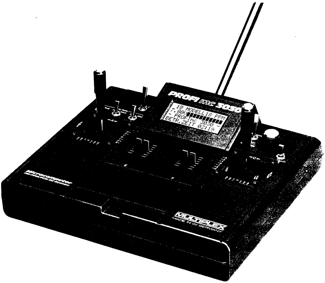
In purchasing the PROFI mc 3030 you have acquired a product of the highest quality, with all the advantages of being "Made in Germany". We thank you for your faith in our company.
As in all top-class radio control systems the capabilities of the equipment are concentrated in the transmitter, which offers a tremendous wealth of features and facilities. The transmitter also embodies an entirely new method of setting up and controlling these features, designed specifically to make these advantages easier for the modeller to understand and use.
This new philosophy is based on three elements: "the device guides the user", by means of a "menu system" and "clear, easily understood messages".
With this in mind, you could be forgiven for asking "so why do we need such a fat manual?" And indeed, you may find such a weighty tome rather frightening.
Well, first of all, the PROFI mc 3030 is capable of much more than you can imagine - and we would hate to hide anything from you. Secondly, we have put a lot of effort into making this a manual that any modeller can understand - everything is explained in full.
In spite of this, we have to admit that the familiar "80/20" rule still applies: with only a 20% knowledge of the transmitter, you will be able to exploit 80% of its facilities. And you will soon find out that you only need this manual for the odd special case.
Nevertheless, we would ask you please to read right through this book at least once, and thoroughly. Do this, and you can be sure that you know enough to use the system sensibly. You will also acquire some idea of the vast range of possibilities which the system opens up, even if you have no use for them at present.
We hope and trust that you will have many years of pleasure and success with your PROFI mc 3030.
About this manual
If you have some prior experience, and want to "get down to it" as quickly as possible, please turn to the Section entitled "Quickstart", which precedes the main text of the manual.
The remainder of the book is divided into two main parts.
The first part:
describes and explains the transmitter and its wide-ranging facilities.
This part of the manual is designed and organised in a logical, tutorial-style sequence, so that it makes sense to read it right through while you become familiar with the equipment; at the same time it serves as an excellent reference source for later.
Initially the text discusses the hardware, then the main screens which you will encounter on the LCD display. Although the menu system makes the transmitter just about perfect for the "DIY programmer", a series of ready-made "programs" (as they used to be called) is supplied as standard, and these are described and explained next.
After this the learning curve becomes somewhat steeper (don't worry, it's not as bad as it sounds) as we cover the transmitter's facilities in depth. First you will learn about the procedures and facilities which are needed most frequently. After that we deal with those which crop up less often, and some which only the advanced modeller is ever likely to use.
Please don't think that you have to know and understand everything about the transmitter right from the start. If you come across something that does not seem to apply to you, skip it for now, and read it later on, perhaps when you find that you really do need it.
If you are an old hand at this sort of thing, please be sure to read with particular care the Sections which are concerned with memories, switching memories "in flight", and the "Gx" and "Sl" switches. These are the facilities which are not available with any other radio control set.
The second part:
deals with the receiving system: consisting basically of the receiver, the servos and the battery. As there are no substantial differences in this area from earlier radio systems, this part has been kept rather more brief.
However, if you are a beginner to the world of model radio control technology, it is important for you to read this part very carefully, absorb the information, and observe our recommendations as far as possible.
The manual includes an appendix which explains some of the technical terms which crop up most often in discussions of model aircraft control systems.
If you are a beginner, the next suggestion is aimed squarely at you:
No matter how fat, a single manual on radio control equipment can never provide you with all the knowledge you need in order to operate the more complex and demanding models successfully. So: read all the magazines and books you can get hold of - there are plenty of them about.
And one more thing: please join a club, if at all possible. There you will meet people with similar interests, who will be only too pleased to pass on the benefit of their experience.
The legal side
Nothing too onerous here, but there are a few regulations which we have to heed.
You must have a licence to operate a radio control system - and in fact you need a licence just to own one. The PROFI mc 3030 is a type-approved system, so you will have no problem obtaining a licence.
If you intend operating the system in the 40 MHz band, the "General Licence" supplied with the set is all you need. Carry it with you when using the set, as it must be produced on demand if an official of the Post Office demands to see it.
You must notify the appropriate authority if you intend using a system in the 35 MHz band. Please apply for your licence on the form supplied with the system; you have to fill out the form with your personal details.
Systems operating in the 35 MHz band may only be used to control model aircraft.
Important: The transmitter may only be used with the following RF modules: Order No. 4 5668 DBP licence No. MF-142/83 (27 MHz band) Order No. 4 5672 DBP licence No. MF-142/83 (40 MHz band) Order No. 4 5671 DBP licence No. FE-78/83 (35 MHz band).
It is not legal to use the system with other (older) RF modules.
We strongly recommend (although sadly it is not obligatory) that you take out third-party insurance for your models, or add an appropriate extension to your personal insurance policy.
The operation of working models - especially of model aircraft - carries inherent risks which ought to be covered. And even though you may be comprehensively insured, it is still vital that you operate your model with safety in mind at all times.
Very important: as in the case of a private car, your licence and your insurance are invalid if you carry out modifications to your radio control equipment. The operating licence applies exclusively to series-approved equipment and any approved expansion units.
For model aircraft above the legal weight limit it is necessary to obtain an exemption certificate before you fly. We strongly recommend that you join a model flying club. Many clubs are affiliated to one of the national governing bodies, and insurance is often an integral part of membership.
Quite apart from these benefits, a club can offer you help, answer your questions, and help you to solve the myriad problems which you are bound to encounter.
"Quickstart"
 After purchasing a new radio control system most modellers want to see it in action as quickly as possible - to find out whether it works, if nothing else. If this description fits, then this section is for you. It provides brief instructions, with little in the way of explanation, on how to get started with your PROFI mc 3030.
-
Charge the transmitter and receiver batteries as described on pages 9 and 84. If you are in a real hurry, and have access to a MULTIPLEX automatic rapid charger, then you can use that.
-
Connect the components of the receiving system, as shown on page 81.
-
Check that the RF module is plugged into the transmitter, and that the transmitter crystal (blue) is plugged into it. The receiver must be fitted with the receiver crystal (same Channel No.); for a single superhet receiver this has a yellow tag, for a double superhet receiver a clear plastic holder.
-
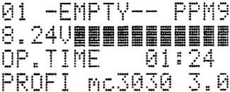
Switch on the transmitter. The LCD display will now show a screen similar to this:
01 -EMPTY-- PPM9 8.24V▐▐▐▐▐▐▐▐▐▐▐▐▐▐▐▐ OP.TIME 01:24 PROFI mc3030 3.0
The top line shows the memory No., the name of the "current" model (or EMPTY), and the transmission mode (PPM7, PPM9, or PCM) used for that model. The second line shows the transmitter's operating voltage; first in digital form, then in the form of a "bar graph".
Line 3 displays the cumulative operating period, and line 4 shows the type designation of the transmitter.
The top line of the display may not be exactly as shown; this depends on whether your dealer has prepared the transmitter for you in advance.
- As supplied, the transmitter's memories 1 - 5 are vacant; memories 6 - 15 contain "ready-made programs".
If your dealer has not already done so (in which case you only need to switch on), you now have to select one of these "programs". Or - better - copy one of them into one of the vacant memories. Then you can experiment with it without worrying about changing anything in the original, which may well be extremely useful to you soon.
To copy a "program", you have to do two things:
-
If you do not see memory No. 01 at top left in the display, you will need to change to that memory (i.e. to 01).
-
Then you will copy one of the "ready-made programs" into this memory.
This is how you do it:
- If you see memory No. 01 at top left in the display, skip this stage and go straight to point 7. If not, you must first switch to this memory.
Press keys M ▢▢ in succession. The transmitter will confirm each key press with a bleep. Your display will now look like this:
01 EMPTY PPM9
CHANGE TO FILE NO. L01:-EMPTY--
What you see in the top and bottom lines depends on what, if anything, your dealer has done for you beforehand; in any case it does not interest us now. However, lines 2 and 3 should look as shown in the illustration above. If that is not so, then you have made a mistake. In this case press the M key repeatedly until you see the starting screen, and try again.
We will assume that it has worked correctly. Now press the ▢ key. The number in line 4 starts to flash. Now press the ⊕ or key until the number 01 appears. It should also be flashing.
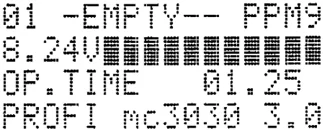
Now press the M key four times; you are finished, and will see the starting display again, except that now memory number 01 will be displayed:
01 -EMPTY-- PPM9 8.24V▐▐▐▐▐▐▐▐▐▐▐▐▐▐▐▐▐▐ OP.TIME 01.25 PROFI mc3030 3.0
If you see a model name after 01, instead of EMPTY, don't worry - it's all in order.
- Now it is time to copy a "ready-made program" into this memory.
Depending on your particular interests, select one of these two:
3
"FIESTA" (glider) from memory No. 6, or "BIG LIFT" (powered model) from memory No. 10, or "HELI-BOY" (Schlueter-type helicopter) from memory No. 13.
As helicopters make greater demands on the radio system, they are not so suitable for a quick start with the new system. Unless, that is, you have plenty of experience with computer-based radio control systems.
You will now copy one of these two models into memory No. 1, as follows:
Press these keys in succession: [M] [-] [+]. The transmitter will confirm each press with a bleep.
The screen should now look like this:
-- FILE COPY -- F MODE:FULLY FR. 01:-EMPTY-- TO 01:-EMPTY--
(Here again, it makes no difference if there is a model name after the No. 01, instead of "EMPTY".)
If the display is different, you have either forgotten one of the keys, or you have pressed a wrong key. In this case press the [M] key repeatedly until you arrive back at the starting screen. Try the procedure again.
Press the [-] key. The number 01 in line 3 (after "FR." = from) will start to flash. Now press the [+] key repeatedly until the number 06 (for "FIESTA") or 10 (for "BIG LIFT") appears, and flashes. The display will show the corresponding name after the number.
You have now "told" the transmitter what you want to copy.
We already know where you want to copy it: that is shown in line 4: "to 01".
Press the [M] key. Now nothing will be flashing, and line 4 will look either like this:
TO 01:FIESTA
or (depending on your choice) like this:
TO 01:BIGLIFT
hat's the job done. Now press the [M] key three times, and you are back where you started.
8. You could meet a slight problem at this stage: All the models stored in memory are for the "PPM" transmission mode.
If you have purchased your PROFI mc 3030 with a PCM receiver, you must now switch to the correct transmission mode.
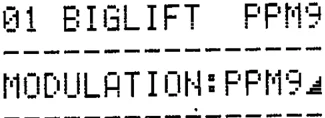
To do this, press these keys in succession [M] [-] [-] [-], and you will see this display:
01 BIGLIFT PPM9 MODULATION:PPM9
Press the [-] key, and "PPM9" will flash. Now press the [+] key, and "PPM9" will turn into "PCM".
Press the [M] key four times, and you will be back to the starting screen. The job is done.
9. If you now switch the transmitter off and on again (it's not necessary, but do it nevertheless), you will see that it has remembered the new settings. Unless and until you switch to a different model, you will always find the transmitter set to this model and this transmission mode when you switch on.
Now you are ready to try the system out. However, before you start worrying about why the system is not working, check the transmission mode. This is always shown in the first line of the display, on the right.
Three modes are possible:
- PPM 7 = for all PPM receivers which cannot decode 9 channels. If you possess such a receiver (e.g. red 4/6 channel receiver) with the transmitter set to PPM 9, the first two servo output channels will not work correctly.
- PPM 9 = for all PPM receivers, except those mentioned in 1).
- PCM = all MULTIPLEX PCM receivers.
If necessary, switch to the transmission mode as described above.
The next step is to have a look at pages 20 to 24 to get an idea of all the things you can do with the model (or program) that you have selected.
However, before you can put the system to serious use, you will need to activate the throttle ratchet, and set up the transmitter for throttle-left or throttle-right, depending on your preference. See pages 8 and 19 for details.
1. The transmitter

Hard... or soft... No question: this is "hardware"
Transmitter front face - notes on operation
Charge socket Power indicator Aerial socket tension screw Digi-adjusting
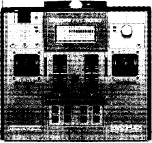
keypad lift here Fig. 1
Power indicator
Just to the right of the ON/OFF switch is an LED which glows when the transmitter is switched on. If the reserve battery system, Order No. 7 5710, is installed, the LED flashes when the transmitter is being powered by the reserve battery.
Charge socket
The charge socket is on the left face of the transmitter, close to the top. Naturally the transmitter charge lead is plugged in here; the socket is also used for the Teacher/Pupil lead, for the Diagnosis lead, the transfer lead and the rev-counter sensor.
Aerial socket tension screw
This screw is used to adjust the friction of the swivelling aerial socket. Rotate it clockwise to increase the friction, but take care not to over-tighten the screw, as this might damage the swivel. If necessary, tighten the screw to the point where the (fully extended) aerial just holds its position reliably. Make any adjustments in very small steps, check the effect, and adjust again if necessary. Over-tightening the screw can damage the swivel bearing.
Slider control "markers" (Fig. 2)
The sliders are fitted with a new form of marker - an extra slider. This is a highly practical feature, as it enables you to shift the slider to a previously set position by feel alone: for example, to a particular flap position. Simply squeeze the slider and the marker together between thumb and forefinger until they coincide.
Please note: in each case the "outboard" slider (the one nearest the stick unit) is the actual slider control: the "inboard" ones are the markers. The markers are fitted with a fine ratchet which can be disengaged for adjustment purposes. To do this push the marker slider outwards - towards the actual slider control - then move it to the correct position. Do not force it along the ratchet - the ratchet will last longer if you treat it gently!
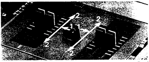
Fig. 2
Transmitter control symbols
All of the controls are designated by a letter; for example B is the forward/aft plane of the left-hand stick unit, and C is right/left on the right-hand stick. These letters are a useful shorthand method of referring to the controls. These letter symbols are used all the time in this text, and you will use them whenever you use the transmitter.
Stick unit trims (Fig. 3)
Basically the trims - apart from the throttle/spoiler stick - work on the "Centre-Trim" principle. This means that the end-point values are unchanged when the centre position of a stick function is shifted electronically (by moving the associated trim lever).
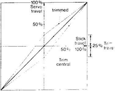
The throttle/spoiler stick incorporates the idle trim feature: this means that the trim slider only works at one end of the stick arc (idle); at the other end-point (full throttle) the trim has no effect. Please turn to page 41 for details of how to set up the idle trim facility.
"Digi"-Adjustor
The Digi-Adjustor has the same function as the \oplus and \ominus keys on the keypad, and is automatically connected in parallel with these keys, whenever that serves a useful purpose. Turning the knob to the right by one click-stop has the same effect as pressing the \oplus key once; turning it to the left by one click is the same as pressing the \ominus key once.
This adjustor has no "zero" or centre point, and no end-points! Don't worry - there is no possibility that you might "overwind" it. Once you reach the end of a particular adjustment range, it ceases to have any effect.
When to use it: Whenever you wish to adjust any function over a considerable range. However, its main purpose is for making adjustments to the model when it is in flight, e.g. for adjusting aileron differential during test flying.
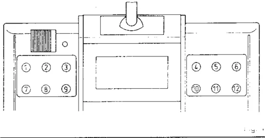
The switch bays
On either side of the LCD screen, at the top of the transmitter front face, are two wells, each of which can accept 6 switches or similar accessories. They are numbered 1 to 12 as shown in Fig. 4. As supplied, the transmitter has four switches on the left and two switches plus the Digi-Adjustor on the right. You can fit extra units by installing the well inserts which are supplied with the set: see page 75. Legend stickers are also supplied, including some blank ones which you can inscribe yourself.
Opening and closing the transmitter Changing the RF module
Opening the case
Hold the transmitter as shown in Fig. 5. Press the latch buttons down with your thumbs, then fold the back panel down towards you. Always close the keypad flap before opening the transmitter.
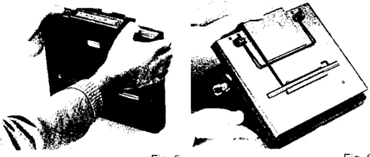
Fig. 5 Fig. 6
Closing the case
This is best carried out as shown in Fig. 6. Hold the transmitter front as shown. Engage the lugs at the bottom of the back panel, then fold the back panel up until the latches snap home. If the latches do not immediately engage, press in slightly at the sides.
Before closing the transmitter always check that no wires are trapped; especially around the stick units and over the well for the keypad flap: there is no clearance at all at this point!
If the cables are organised logically inside the transmitter, there should be no danger of wires becoming caught up or jammed. Nevertheless - always check one last time before closing the back!
Changing the RF module; changing crystals
Grasp the module at the recessed points (Fig. 7), then pull it up and out of its holder.
The crystal is plugged into the side of the RF module (Fig. 8). Pull out the crystal by its plastic tag. When plugging in a crystal make sure that both pins engage correctly in the socket in the module.
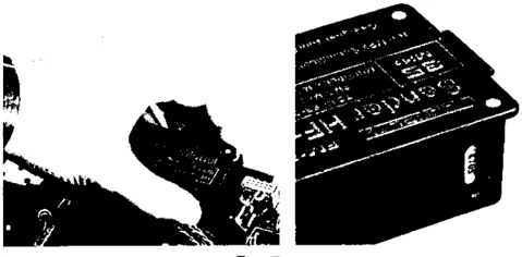
Fig. 7 Fig. 8
Before plugging the module in again, bend the plastic tag over to one side.
When refitting the module do not press down in the centre of the unit, but around the finger recess position. This will help to ensure that it is fitted squarely, thereby avoiding damage to the contacts.
Transmitter back panel
Inside
On both sides there are holders for a spare pair of crystals and a replacement fuse. Please note the specially formed holder for double superhet receiver crystals and their correct position in the holder (Fig. 9).
Outside
There is a well in the outside of the back panel which accommodates the transmitter aerial for transport. The support bar can be set to three different positions: folded in flush, at right-angles to form a back support, and upright as a carrying handle. Please refer to Figs. 10 to 12.
 Fig. 9
Don't lever them - slide them
Fig. 10
Fig. 11
Fig. 12
Inside the transmitter
Fuse
Take a look at Fig. 13. The basic purpose of the fuse is to protect the transmitter against excessive currents during rapid charging. If the fuse burns out, replace it with the same type (5 x 20 mm, 2 Ampere, quick-acting - standard commercial item). Charge currents higher than 2 A may cause damage to the transmitter electronics!
Cable compartment
The leads from the various switches are stowed away inside the cable compartment (Fig. 14). To open the compartment push one of the spring latches to one side and lift the cover off. Pass the wires from each connector into the compartment through the nearest opening. Lead them out again through the openings on the side nearest the RF module. Part of the "excess" cable length can be accommodated inside the compartment. Any spare cable is best left at the switch position. Always arrange the wires carefully and neatly, to avoid the cables forming a mass of unruly "spaghetti" around the stick units or close to the keypad cover well.
 Fig. 13
Fig. 14
The connectors
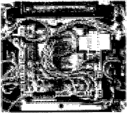
Three sides of the main electronics circuit board are exposed, each fitted with connectors for the "peripherals", i.e. stick units, switches and so on. See Fig. 15.
Starting from the left, these are:
DE
Digi-Adjustor. If you plug this in the "wrong" way round, the [+] and [-] functions will be reversed.
MNT
MULTINAUT. Only for connecting a MULTINAUT control module (for model boats - the same MULTINAUT system is used in the COMBI 90).
 KnR
Right-hand stick unit.
E
Control "E". This is normally the left-hand slider control.
F
Control "F". This is normally the right-hand slider control.
T
Keypad. Can be plugged in either way round.
G
Control "G". Normally this is a switched channel. Plug it in the opposite way round and the direction of operation of the switched channel is reversed.
H, I
Controls "H" and "I". These are reserve inputs for special purposes. Not used in the standard version.
KnL
Left-hand stick unit.
S1 to S5
Inputs for the change-over/coupling switches S1 to S5. More on this on page 14.
L/S
Teacher/Pupil switch. If you install a switch for Teacher/Pupil operation (the buddy box system), it must be plugged in here.
7
M Memory switch. If a switch is installed for this purpose, it must be plugged in here. Plug it in the "wrong" way round and the selected memories are interchanged.
Note: When connecting auxiliary controls and switches please refer to the explanation of the "TEST Controls" menu on page 77.
Activating the stick ratchet
As supplied, both vertical axes of the dual-axis stick units are self-neutralising. Most modellers will want to remove the self-neutralising action from one stick (the "throttle" stick), and activate the ratchet instead.
Removing the neutralising spring
Open the transmitter. Select the stick from which you want to remove the neutralising spring, and set it to the position shown in Fig. 16. Disengage the neutralising spring using tweezers or pointed-nose pliers. Remove the spring, and the neutralising arm will come away too. Keep these components carefully - one day you may need them again. The stick is now non-neutralising in one plane, but the ratchet is not yet active. Many pilots like the throttle stick like this; especially for the collective pitch / throttle stick arrangement used with helicopters.
Activating the ratchet
At the base of the stick unit you will see a screwhead (Fig. 17). Undo this screw about 4 complete turns, counter-clockwise. This releases the ratchet spring fitted to the stick unit, and activates the ratchet.
 Fig. 16
Fig. 17
8
Charging the transmitter battery
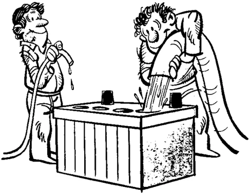
The transmitter is fitted with a 6-cell sintered-cell battery of 1700 mAh capacity, which provides an unusually long operating period of more than eight hours from a single charge. The EUROPA-Edition is fitted with a 1350 mAh battery, giving about 5 hours' operation. Note: these values were measured using perfectly charged batteries, and lasted until the batteries were completely discharged (transmitter no longer working). Charge up your transmitter pack as soon as the battery monitor warns you. Depending on your chosen method of charging, the monitor will trip after 5 - 6 hours' operation. Compared with earlier transmitters, recharging must be carried out at a higher rate, and/or for a longer period, in accordance with the high battery capacity.
Slow charging
The charge current should be about 170 - 200 mA. At 200 mA a full charge is achieved in about twelve hours. At the 170 mA rate it does no harm to continue charging beyond the twelve hours, as there is no danger of over-charging.
Older types of charger are often unable to supply a current of around 200 mA, or only under certain circumstances, and for this reason we recommend the new MULTIPLEX charger, Order No. 14 5545, which is specially designed for the requirements of the PROFI mc 3030. The MULTIPLEX Combi-Charger, Order No. 14 5540, can be used to charge the battery in a makeshift fashion: select the 100 mA outlet and charge for at least 24 hours. At this current you can leave the transmitter connected to the charger constantly; it is not possible to damage the battery or the transmitter at such a low current. Be sure to switch the transmitter off before recharging. Then connect the transmitter (charge socket) to the charger using the charge lead supplied. Red plug = + (positive) socket on the charger, blue plug = - (negative) socket.
Rapid charging
The transmitter can be rapid-charged in only 1 to 2 hours. However, to do this safely you must use the MULTIPLEX Automatic Rapid Charger, Order No. 9 2505. If you use a different rapid charger, or a different charging process, there is a danger of damaging the battery and the transmitter. We would not be able to repair the unit under guarantee under such circumstances. If you possess a charger which is not compatible with the protective circuitry of your new transmitter, please contact our Customer Service department. For rapid-charging select an output current of 1 - 2 A. Provided that you are using the recommended charger, you do not need to concern yourself with the battery's initial state of charge. At the 2 A rate, and with a completely discharged battery, the charge period is about one hour; in any case the charger switches itself off when the battery is fully charged. Caution: the charge rate must not exceed 2 A. At higher currents the transmitter fuse will burn out. Do not be tempted to install a higher rated fuse, as you risk damaging the transmitter. If you damage the transmitter by exceeding the recommended charge current, we will decline to repair it under guarantee.
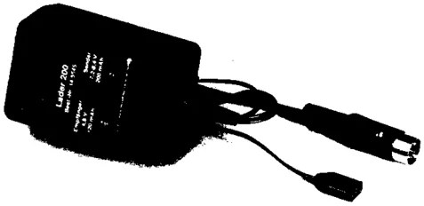
Fig. 18
Note: A brand new battery cannot exploit its full capacity right from the outset. In fact, it only achieves full capacity after a few charge/discharge cycles (5 to 10). Please bear this in mind when you start using the equipment, as the full operating period will not be available at first. If you need full battery capacity at once, we recommend that you charge the transmitter, leave it switched on until the battery is completely discharged, then recharge it fully. Repeat this cycle several times.
9
The keypad and the menu system
The first part of this Section explains how the keypad is used. After this you will find a brief introduction to how the "device guides the user" through menus. The Section is concluded with a brief explanation of the transmitter's menu structure.
The keypad
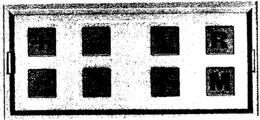
Fig. 19 These eight keys, used in conjunction with the LCD screen, give you complete access to all the selection and adjustment functions. The keys are in three groups, and it is easy to remember what they do. Very briefly, the keys have the following functions: The Ⓜ key This is the "Menu" key. You use it first to move from the "Status" display into the "Menu tree". Within the menu tree the Ⓜ key is always used to conclude any procedure, and to move back into the preceding menu. Regardless of where you are in the menu tree, you can return to the Status display at any time by pressing this key one or more times.
The Ⓡ key R stands for Reverse - that's all there is to say. This key is used to reverse a servo, or switch something off or on. More on this in the explanation of the individual menus.
The ⊕ and keys These keys are also more or less self-explanatory. If something is to be increased or reduced, then you do it with these two keys. You can also use them to "leaf through" lists of options at many places in the various menus. Examples of using the ⊕ and ⊖ keys:
- Adjusting servo travel
- Adjusting a mixer input value
- Switching to a different memory
- Moving on to the next transmitter control when testing etc.
One special feature here: where it is of practical use, these keys feature an auto-repeat function. If you press the key briefly, its action occurs once. If you hold it pressed down, the action is repeated automatically. You simply need to press the key and watch the display, then release it when the required value is reached. If you "overshoot", press the opposite key to go back again. For instance, if you wish to change a mixer input from 0 to 70, this is somewhat easier than tapping the ⊕ key 70 times.
Whenever it makes sense, the Digi-Adjustor (see page 6) is connected in parallel with these two keys. You can then choose whether the keys or the rotary knob is the more convenient to use.
The ◀◼◼▶ keys These are the "selector" or "arrow" keys. The rectangular arrangement is deliberate: when you are at a particular menu (wait a moment - we're nearly there!) you will see triangular symbols, or selector tags, in the display, which correspond to these keys. They are always in approximately the same "corner" of the screen. If you press one of these keys, you select that point in the display which is adjacent to the corresponding symbol.
We don't want you to get complacent, so here are two (slight) complications:
- If there are only two possible selections in a particular menu, only two selector tags are displayed, and only the corresponding two keys are "active". If you press one of the other keys, nothing happens.
- Within any of the "Adjustment" menus the arrow keys are also used to "release" or "activate" particular points. The "free" or "active" point then starts flashing. Don't worry if this is not clear - it's all much easier to do than to describe.
A brief recap: Symbol in the display = key with same symbol. The key is "in the same corner" as the symbol in the display. When you press one of the keys, you select the point in the menu which is adjacent to the same symbol in the display.
Now for a quick practice session: (We assume here that you have copied "BIG LIFT" into memory 01, as described in "Quickstart", and that this is still the current memory.)
10
Switch the transmitter on, and you will see the Status display. Press the [M] key. You are now in the "root" menu - Menu 1:
-- ADJUSTMENTS-- [FARROW]SERVO CONTROL[FARROW] ---- MENU 1 ---- [LOWARROW]FILES MENU2[LOWARROW]
Press the [UPARROW] key, and you are at the "Servo adjustment" menu:
01 BIGLIFT PPM9
- SERVO ADJUST - [FARROW]TRVL+REV LIMIT[FARROW] [LOWARROW]CENTRE TEST[LOWARROW]
Press [M] to return to the root menu 1. Try pressing the [DOWNARROW] key: you arrive at root menu 2:
01 BIGLIFT PPM9 ---- MENU 2 ---- [FARROW]TIMER ASSIGN[FARROW] [LOWARROW]OP.TIME MENU3[LOWARROW]
Press the [UPARROW] key again, and you are at root menu 3:
01 BIGLIFT PPM9 ---- MENU 1 ---- [FARROW]PUPIL RPM[FARROW] [LOWARROW]TEACH. PCM/PPM[LOWARROW]
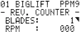
If you press the [DOWNARROW] key, you land up at the rev. counter - just as you would (we hope) expect, as that is what the display promises:
01 BIGLIFT PPM9
- REV. COUNTER - BLADES: 1[FARROW] RPM : 000
As we have no use for this at the moment, press the [M] key repeatedly until you arrive back at the Status display. You now know how the selector keys and the [M] key work. We will get to the other keys later.
The Menu System: makes choosing easy
In the "Keypad" section which you have just read, you learned virtually all there is to know about navigating your way from one menu to another. Now we explain the principles behind the system.
In the world of "real" computers the development of the "menu-based user interface" has been one of the most important steps in masking the stony, unflinching face of the computer, and making it acceptable and accessible to the ordinary mortal.
The basic system works like this: The computer provides a list of options in the form of a menu, which shows everything that it is ready to carry out at any one moment. From the options on offer the user selects what he wants.
Since the computer usually has a vast array of capabilities, it is generally the case that the particular option you want cannot be selected in a single step. After all, if the computer were to offer just one, extremely lengthy list of options, then it would be difficult to see what was on offer, and sort out what you want. It would be very difficult to make sense of a restaurant menu with 50 different dishes on one page.
Keeping to the restaurant analogy, the sensible restaurateur spreads his menu over several pages, grouping all the meat dishes in one section, all the fish in another, and so on. If you have a hankering for a veal cutlet, you would look it up like this: main courses - meat dishes - "veal". A real menu usually has no contents page. If what you are looking for is not on page 1 ("Menu 1"), then - assuming that it is not something really exotic - you might hope to find it on page 2 ("Menu 2"). The menu system of the PROFI mc 3030 works in exactly this way.
Take a look at the diagram on page 12, which represents the options offered by the PROFI mc 3030 in a slightly simplified form.
In your last experiment you learned that the [M] key takes you directly from the Status display to the menu proper, i.e. to Root Menu 1.
By selecting "SERVO" (top left) you move to the "Servo adjustment" menu, where you can set up many options, if you wish.
By selecting "CONTROL" (top right) you move to the "Transmitter Controls" menu, where there are also several possible options for you to choose.
Select "MEMORY" at bottom left, and you find a menu which copes with everything to do with memories.
For the moment, the "bottom right" option hides everything else which the transmitter has to offer, via Menu 2. You might like to think of this option as "more" or "contd.".
In Root Menu 2 things continue in the same way:
01 BIGLIFT PPM9 ---- MENU 2 ---- [FARROW]TIMER ASSIGN[FARROW] [LOWARROW]OP.TIME MENU3[LOWARROW]
On the left you get to the stopwatch and the operating period timer; on the right to "Assign" and "Menu 3". Because of the similarity to a tree - albeit one growing upside-down! - this type of menu arrangement is often known as a "menu tree", or - more technically, as a menu structure. The core of the structure is formed by the Root Menus 1 to 3.
PROFI mc 3030
menu structure
Menus ABCD: details on facing page
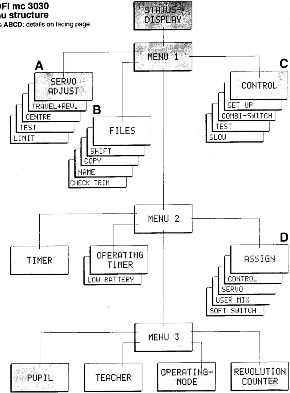
Have a look at the diagram above. You will see, for example, that there are four more menus hidden behind the "Memory" menu.
This is intended to show that there are four "dead ends" which are accessible from the "Memory" menu; in this case they are "Copy", "Shift", "Name" (enter, change), and "Trim" (check, match).
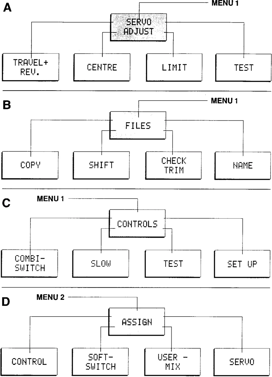
The same applies to three of the other branches of the tree. To avoid confusing the main diagrams, these "sub-menus" are shown in detail on page 13.
Using this branching system you can always reach your destination, i.e. get to the point where you want to adjust or assign something, just by pressing a few keys.
12
A
MENU 1
SERVO ADJUST
TRAVEL+ REV.
CENTRE
LIMIT
TEST
B
MENU 1
FILES
COPY
SHIFT
CHECK TRIM
NAME
C
MENU 1
CONTROLS
COMBI- SWITCH
SLOW
TEST
SET UP
D
MENU 2
ASSIGN
CONTROL
SOFT- SWITCH
USER - MIX
SERVO
As you know, once you are within the menu tree, you always move further on by pressing one of the selector keys.
You always return with the Ⓜ key.
The overall result:
You don't need to learn any codes or confusing computer terminology. In fact, you will find that you don't even need the tree diagram after a while, as the plain English texts guide you easily through the menus. Our sole purpose in explaining the principle is to ensure that you have some idea of what you are doing when you press the various keys.
And anyway, a little understanding never hurt anyone.
The menu tree is arranged in such a way that it is quicker to get to the commonly used functions than to the rest. If you happen to need the rev counter every time you fly, then you are, alas, the exception which proves the rule.
13
Transmitter controls and switches

This section is necessarily somewhat dry and theoretical, and you can skip it for the moment if you wish. However, sooner or later you will need to absorb some of this information, particularly when installing auxiliary switches or other expansion units.
As we have already seen on page 7, where the internal connectors are described, there are several different types of connector.
First there are the connectors which have one purpose only: Digi-Adjustor (DE), MULTINAUT (MNT), Keypad (T) and Memory Switch (M). There is not much to say about these sockets - each unit must be connected in the correct place.
Next comes the group of "letter inputs": A to I. These are connectors for the transmitter controls. Here a brief explanation is necessary: the inputs A, B, C, D are not shown individually; they are grouped together as "KnL" (left-hand stick = A, B) and "KnR" (right-hand stick = C, D). The stick units must also be connected to the correct sockets (KnL and KnR).
The remaining inputs are marked S1 to S5 and L/S. This is where "change-over switches" and "coupling switches" are connected.
What are transmitter controls? Well, in coarse terms, these are all the "movable elements" on your transmitter, which you use to operate something on your model. They include the two stick units, the sliders, and also, for example, the switch which you use to release the aero-tow mechanism.
So what are change-over switches and coupling switches?
These switches are usually used not to actually move something on the model, but, for example, to switch between different pre-set values (such as Dual Rates) or to activate coupled controls (e.g. Combi-Switch, or a flap/ elevator coupling switch).
Two "extras" for the expert: The switch "SI" is a special-purpose feature which does not fit into our neat scheme. It is a 3-stage switch, and should really be included as a "transmitter control", as it is connected to input "I". However, it can be used in a similar way to one of the change-over or coupling switches; especially in combination with the "Fixed Value" option, of which more anon.
There is also a software switch (i.e. it does not exist in hardware form) called "Gx".
An explanation of these special features would only confuse matters at this point. Please see page 76 in the Section entitled "For experts".
Now we come to one further difference, and a possible source of confusion. According to what we have just said, a switch can be either a transmitter control or a change-over or coupling switch, depending on where it is connected inside the transmitter. But this is only partly true:
Change-over switches and coupling switches have a 2-core connecting lead. A switch with a 3-core lead cannot be used for this purpose.
Switches which act as transmitter controls may have either a 2-core or a 3-core lead. For a simple ON/OFF switch (2-position) the lead is 2-core. For a 3-stage switch it must be 3-core.
Why? When you plug in a switch, the transmitter control input "sees" whatever the unit is as a potentiometer. So the input sees a switch as a crude pot, which can only be set to its end- point values.
And one more note In line with what we have just said, it is perfectly possible to connect switches (preferably 3-position switches) to inputs E and F instead of the standard sliders. This can be a useful feature for special models which require many switched channels.
On the other hand inputs G, H, I can also be used with further pots instead of switches.
Most users of the PROFI mc 3030 will hardly ever need these features. Our intention in presenting this brief excursion into the "realm of the unused features" is just to give you an idea of the flexibility and versatility of your new system.
What this all means in practice: When you assign or adjust transmitter controls, you will always find yourself dealing with the "letter" abbreviations. When you are assigning change-over switches or coupling switches, you will be dealing with S1 to S5 and L/S. When fitting auxiliary switches you must bear in mind the number of wires in the cable.
14
Special-purpose menus

The "Operations" or "Status" display
(Here again we will assume that you have copied "BIG LIFT" into memory 01, as described under "Quickstart" - and that you have not switched to a different memory. Of course, what we are going to say next applies to every other model memory.)
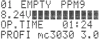
When you switch the transmitter on, the Status display will appear on the LCD screen. It provides a summary of the most important things you need to know for controlling your model:
01 EMPTY PPM9 8.24V▮▮▮▮▮▮▮▮▮▮▮ OP.TIME 01:24 PROFI mc3030 3.0
The top line: 01 = number of the "current" memory. This is always the memory (or "list") which was in use last time you operated the system. This usually means: the model that you last flew. BIG LIFT = Name of the model in English. That's easier than remembering a number, isn't it? PPM = Transmitter's current transmission mode (modulation). Also the same as the last time you used the set.
The second line:
8.24V▮▮▮▮▮▮▮▮
8.24 V = transmitter battery voltage. The digital value is very accurate, but unfortunately not easy to assimilate at first glance - a drawback of all digital displays. Immediately after a full charge the voltage is about 8.2 -8.4 V. At 6.9 Volts the battery monitor trips, and the battery should be recharged.
Next to the digital display is a "bar" consisting of up to 11 "boxes". This is an analogue version of the digital voltage display; it is easier to understand at a glance, but it is not so accurate. Consider it as a rough indicator of battery voltage. The battery discharges steadily while you are using the transmitter, and at the same time the boxes are gradually erased from right to left; i.e. the bar becomes shorter. Because of manufacturing tolerances, and the inherently approximate nature of the bar, the display is not as accurate and reliable as the digital display, but it gives you a useful idea of how things are going.
The third line:
OP.TIME 01:24
A very useful feature: The operating period display At any time you can see how long the transmitter has been in use since the last time the timer was reset to zero (you can do that at any time - see page 16 for further details).
The timer is cumulative, and it makes no difference how often you switch the transmitter on and off; the operating period timer stops counting when you switch off, and continues when you switch on again.
In practice the best way of managing the timer is as follows: set it to zero every time you recharge the battery. The display shows hours : minutes.
Bottom line:
PROFI mc3030 3.0
This line of the display will normally show the transmitter type designation "PROFI mc 3030", but there are exceptions:
You can ask the MULTIPLEX Service Department to program in your name. This is designed as a security feature, and to prevent confusion over ownership, so you cannot change it yourself.
If you have activated the transmitter's stopwatch, this line automatically shows the stopwatch display:
TIMER +00:10
Please refer to page 16 for further details of the stopwatch.
But there is one function which always takes precedence: if you connect the rev counter (optional accessory, Order No. 7 5970) to the transmitter, this line of the display shows the rev count. For more details please see page 18.
RPM : 000

How to use the operating period timer
There is not much to say about this timer; all you can do to it is reset it to zero. To do this (starting from the Status display) press [icon]. You will now be at the operating period timer menu:
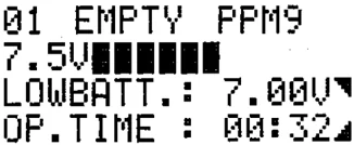
Press the [icon] key; the value displayed will change to 00:00, and you are done. Return to the Status display with [icons]. The operating period display is in the form hours : minutes.
There is nothing else to worry about concerning this timer. When the transmitter is switched off, it records the last displayed time and starts again from the recorded value next time you switch on.
When should I reset the display?
The timer can count up to 99 hours 59 minutes, then it starts again from zero. That's by no means long enough to measure the lifetime of the transmitter, although it might be enough for "occasional flyers" to count their flying time per season.
It makes most sense to reset the timer to zero every time you give the transmitter battery a full charge. The transmitter's operating period from a full charge is around 5.5 hours, so the display gives you quite an accurate idea of how much longer you can fly. But please only consider this value as a guide. Slight differences in batteries and in the transmitter's current consumption can result in variations of up to +/- 20%. Your best bet is to carry out a practical experiment to determine how long your own transmitter actually lasts.
How to use the stopwatch
To use the integral stopwatch you have to do two things:
- You must "tell" the transmitter what you want to use to control the stopwatch. This is usually one of the switches S1 to S5, although the Teacher/Pupil switch can also be used.
However, it is also possible to start and stop the timer automatically, via a particular control function; for example, with the "motor on/off" switch in an electric-powered model. If you wish to make use of this facility, please read the section entitled "The Gx switch" on page 77.
- You have to define the starting value, which also determines the mode of timing (count up or down).
The transmitter will then record the settings you have made in the "list" (or "program") for that model; the stopwatch will then always be available automatically when you select that model. You only have to enter these settings once.
- In addition you can select whether your stopwatch is automatically reset to zero (00:00) when you start it.
1. Defining the operating switch
The hardware definition
From the mechanical point of view you have to decide between a simple ON/OFF switch with 2 fixed end-points (e.g. the Dual Rates switches) and a momentary switch (e.g. the stick end press-button, or the momentary switch, Order No. 7 5710, which is available as an optional extra).
If you use a 2-stage switch the timer runs for as long as the switch is set to "ON". If you use a momentary switch, the timer starts when you first press the button, and stops next time you press it.
Pick the type of switch which seems most natural to you. If you opt for the 2-stage switch, you can use either one of the standard switches (S1 to S3, S5). Of course, the one you choose can no longer be used for its original function, but there are plenty of modellers who would never dream of using all three Dual Rates switches (S1 to S3), or who never use a Combi-Switch (S5), so they would have an obvious choice.
If you want to use a momentary switch then you will have to purchase one. The stick end press-button has to be installed by the MULTIPLEX Service Department. In this case we recommend that you plug the switch connector into "S4"..
The "software" definition
This is carried out at the "TIMER" menu.
From the Status Menu press the keys [icons]. You will see this:
TIME +00:01 START 00:00 ALARM 00:00 SWITCH OFF
Only the bottom line is of interest to us at the moment.
Press the [icon] key. The word "OFF" starts to flash, and you can now change it. Press the [icon] key and "OFF" will be replaced by "ON".
If you press the [icon] key repeatedly, you will see that ON and OFF alternate. At the same time the timer will run as long as "ON" is shown. This is one method of using the timer if you do not wish, or are unable, to dedicate a switch specifically to the timer. As this only works when you are at the "TIMER" Menu, this mode of operation is unsuitable for most applications.
In the following section we assume that you have fitted an extra switch for the timer, and that it is connected to "S4".
Leave the line at "ON" and press the [+] key. "ON" is now replaced by "S1". Press the [+] key again, and you see "S2↓", and so on.
Keep pressing until you see "S4↓".
SWITCH S4↓
16
If you have selected a 2-stage switch, this is the correct setting and you can move to the next section.
If you are using a momentary switch, keep pressing the ⊕ key. After "S5", "LS", "Gl", "SI" you will see "S1↓". The button symbol after "S1" indicates that you can now select the momentary button switch:
SWITCH S1↓
Keep pressing the ⊕ key until "S4↓" is displayed. That is your setting for a momentary switch connected to "S4".
If you need to reverse the direction of action of the switch S4, you do not need to reverse the switch or plug physically; instead simply press the Ⓡ key once. The input field must be active ("S4" flashing) before this works.
That completes the switch definition process.
2. Defining the mode of operation
There are three options here:
- Normal stopwatch (starting value 00:00, counting up).
- Countdown stopwatch. In this case you have to enter a starting value, from which the countdown runs. When it reaches 00:00 the actual timing process is finished. This mode of operation is especially useful for competition flying.
- Count-up or count-down stopwatch (as 1. and 2. above), with cumulative timing (timer does not reset to zero).
1. "Normal" stopwatch mode
We assume that you are still at the "TIMER" menu:
TIME +00:01 START 00:00▎ ALARM 00:00▎ SWITCH S4↓
For this mode of operation you have to set the starting value to 00:00.
If you do not see the word "START" in the second line, this is how you get it: press the ▣ key twice, then Ⓡ once.
If you do not see "00:00" in the "Start" line, this is how you get it: if you have just switched to Start, the minutes field will be flashing; if not you must press the ▣ key, and the "minutes" position will start flashing. Press the ⊕ or keys, or rotate the Digi-Adjustor, to reset the value to "00". Now press the ▣ key again, and the "seconds" will flash. Reset the seconds to zero in the same way.
That's it! Press the Ⓜ key three times to return to the Status display. You will see in the bottom line TIME +00:00. You can now try the stopwatch out to see how it works.
Incidentally the upward arrow only indicates that the timer is working in the "count up" mode.
2. Countdown stopwatch mode
The timer counts backwards from a "pre-set" value towards zero. After a selectable "alarm" period the stopwatch alerts you in the following manner:
When you reach the alarm time the transmitter beeps; After each full minute (if any) before zero it beeps again; Then every 10 seconds;
- Then every second ........ 3 - 2 - 1 - 0; one last, longer beep, and it's over.
After passing through zero, the timer continues counting "upwards", because everybody wants to know how many seconds "late" you were in landing your model. Setting up the stopwatch to work in this mode is hardly more difficult than for the "normal" mode.
First the start time: For example, you wish this to start 2 1/2 minutes before "zero". Press the ▣ key; the minutes at "Start" begin to flash. You will know what to do next: set this value to "02" using the ⊕ or keys, or the Digi-Adjustor. Then set the seconds: press the ▣ key again, the seconds value flashes, and you can set it to "30".
Entering the alarm time:
ALARM 00:00
You enter the alarm period in line three:
Let us imagine that you want the alarm to sound 1 minute before zero. Press the ▣ key, and the minutes value in the "Alarm" line starts to flash. As already described, set this to "01", then set the seconds to "00" in the same way.
Press Ⓜ three times to return to the Status display. A downward-pointing arrow before the time reminds you that the stopwatch is set to the "countdown" mode.
For many applications it can be useful to be able to stop the timer and later start it again without resetting it to zero; for example: to determine the length of a motor run.
To do this, press the ▣ key twice; the minutes field flashes. If you now press Ⓡ once you reverse the mode of operation. The word "RESET" now appears in the display. Set the timer using the ▣ key, and return to the Status display with the Ⓜ key.
One further note
If you do not need the timer again, for any reason, simply move to the "TIMER" Menu and switch it to "OFF", as already described. This action does not lose the values you have entered. If you switch the timer "ON" again later, all the previous settings will reappear. All stopwatch settings apply only to the model in whose "list" the timer and all its settings are entered (the storing process occurs automatically). Thus you can enter and store different settings for every model, if you wish: varying according to the model and the way you use it.
How to use the rev counter
If you want to measure the rotational speed of a model engine, a helicopter rotor, or anything else, you will need the rev counter sensor, Order No. 7 5970, which is an optional accessory. It is plugged into the transmitter's charge socket.
When the rev counter sensor is plugged in, the transmitter automatically shows the rev count in the bottom line of the screen. The Status display will look like this:
RPM : 000
All you need to do now is to enter the number of propeller or rotor blades, to get a correct display of the speed.
Follow this procedure:
Press the keys [M] [↖] [↖] [↘] to arrive at the "REV COUNTER" Menu. You will see this screen:
01 BIGLIFT PPM9
- REV.COUNTER - BLADES: 1 [cursor] RPM : 000
Press [◄]. The displayed blade number starts flashing. Set the correct number of blades with [+] or [-]. That's it done.
Press [M] five times to return to the Status Display.
A few further hints:
As you have an "intelligent" transmitter, it records the number of blades in the "current" model list. If you want to use the rev counter another time on the same model, you do not need to set the number of blades again. However, try as we might, we could not make it clever enough to notice that you changed the 2-bladed prop for a 3-bladed one in the meantime . . .
The "1" option for the number of blades is not as silly as it may appear. For one thing, single-bladed propellers do exist (they are a rare breed, but not yet extinct); for another you can use this setting to measure the rotational speed of a shaft:
To do this you need to mark the shaft in some way, e.g. with tape or paint. The mark should contrast as strongly as possible with the shaft.
The rev count display always shows the speed in rpm (revolutions per minute). The range is up to 25,400 rpm, regardless of the number of blades. Resolution (accuracy) is to 100 rpm.
How to switch between the transmission modes PPM7, PPM9 and PCM
The transmitter can be used with both PPM receivers (e.g. "UNI 9") and with PCM units (e.g. "PCM DS").
You have to set the transmission mode to match the type of receiver you wish to use.
This is how you do it:
From the Status Display press [M] [↖] [↖] [↖] to arrive at the "PPM/PCM" display.
You will see this:
01 BIGLIFT PPM9 MODULATION: PPM9 [cursor]
Press the [↘] key. "PPM7", "PPM9" (or "PCM") will start to flash.
Press the [R] key. PPM will change to PCM (or vice versa). That's all there is to it. Use the [+] or [-] key to change from PPM 7 to PPM 9 and back.
Press [M] five times to get back to the Status Display.
It is only necessary to switch to PPM 7 if you wish to use a receiver which cannot decode 9 channels (e.g. 4/6 channel receivers built in 1979). If you attempt to use this type of receiver with the transmitter set to PPM 9, the servos attached to outputs 1 + 2 will not work correctly.
Pre-programmed models
("ready made lists")
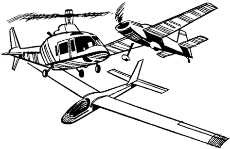
In the transmitter's standard form, memories No. 6 to No. 15 contain "ready programmed" model lists (or programs). These example programs embrace a high percentage of the models which are actually flown by practising modellers.
You can use any of these example lists just by switching to the appropriate memory, as described on page 50. Before you fly your model, you may well have to alter the direction of servo rotation, and that is described on page 34.
You may like to use these examples as the starting point for your own lists. If you do not want to change the "original", first copy it into an empty memory (as described on page 48) and then make modifications to the copy.
The following example lists are available as standard:
Memory No. 6: "FIESTA" – a typical simple glider
Memory No. 7: "SALTO" – a typical glider with V-tail and "flaperons"
Memory No. 8: "F3B" – a typical F3B class glider with "aileron brakes"
Memory No. 9: "CORTINA" – a typical tailless glider
Memory No. 10: "BIG LIFT" – a typical simple powered model
Memory No. 11: "RC1/F3A" – a typical powered aerobatic model
Memory No. 12: "MIRAGE" – a typical delta model
Memory No. 13: "HELI BOY" – a typical helicopter with "Schlueter" rotor head
Memory No. 14: "RANGER" – a typical helicopter with "Heim" rotor head
Memory No. 15: "BK 117" – a typical helicopter with "120 degree" rotor head linkage using virtual swashplate
In all the examples it is assumed that the transmitter is set up as follows: Rudder (or tail rotor) and elevator (pitch-axis) on the right-hand stick Throttle (or spoilers or collective pitch) and aileron (or roll) on the left-hand stick
If you use a different transmitter mode, here are brief instructions on how to change the settings:
Interchanging aileron (roll) and rudder (tail rotor):
- From the Status Display press M◀◀◀. You are now at the "Assign controls" Menu:
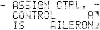
- ASSIGN CTRL. - CONTROL A▲ IS AILERON▼
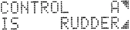
- Assign control A to the rudder, as follows: press ◀++. Result:
CONTROL A▲ IS RUDDER▼
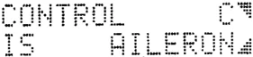
- Assign control C to the ailerons, as follows: press ▶++, then ◀☐. Result:
CONTROL C▲ IS AILERON▼
- Return to the Status Display: press MMMM. That's it finished.
Interchanging throttle (spoiler/collective pitch) and elevator (pitch–axis):
- Move to the "Assign controls" menu with M◀◀◀, as described above.
- Assign control B to the elevator (pitch-axis), as follows: press ▶+, then ◀, and then + repeatedly until ELEVATOR (or PITCH-AXIS) appears. Result:
CONTROL B▲ IS ELEVATOR▼
- Assign control D to throttle (spoiler/collective pitch), as follows: press ▶++, then ◀, then + repeatedly until THROT (or SPOILER or COLL. PITCH) appears. Result:
CONTROL D▲ IS THROTTLE▼
- Return to the Status Display by pressing M five times.
The procedure for assigning the transmitter controls is described in detail on page 30.
19
Example: "FIESTA"
Memory No.: 6
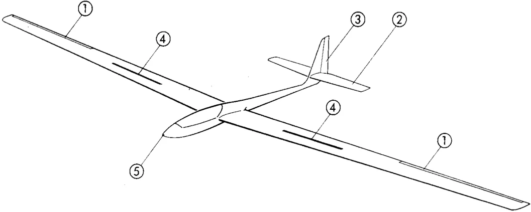
The "FIESTA" is an example of a simple model glider. The ailerons are controlled by a single servo (mechanical differential). The airbrakes are operated with the left-hand stick. "Combi-Switch" supported. An aero-tow coupling, or radio-controlled towhook, if fitted, is operated by a switched channel. A mixer is featured to provide pitch trim compensation when airbrakes are extended. However, the mixing input is set to zero as standard, and the user has to set the value if he needs the feature.
Summary:
ChannelA B C D E FGcontrolsAileron Spoiler Rudder Elevator --- --- Aero-tow
Servo No12345FunctionAILERONELEVATORRUDDERSPOILERTOWHOOKMixer---ELE + --- --- ---1st inp.AILERONELEVATORRUDDERSPOILERTOWHOOK2nd inp.---SPOILER --- --- ---
Note: the "FLAP" input of the "ELEVATOR" mixer must be set to 0; the "SPOILER" input can be set to any value by the user. Switches: S5 = Combi-Switch Adjustments: Combi-Switch: Aileron → rudder, following rate 100%. All servos: travel 100%, centre 0%. Possible modifications: Combi-Switch rudder → aileron, switched off Airbrake operation via slider instead of stick
Example: "SALTO"
Memory No.: 7
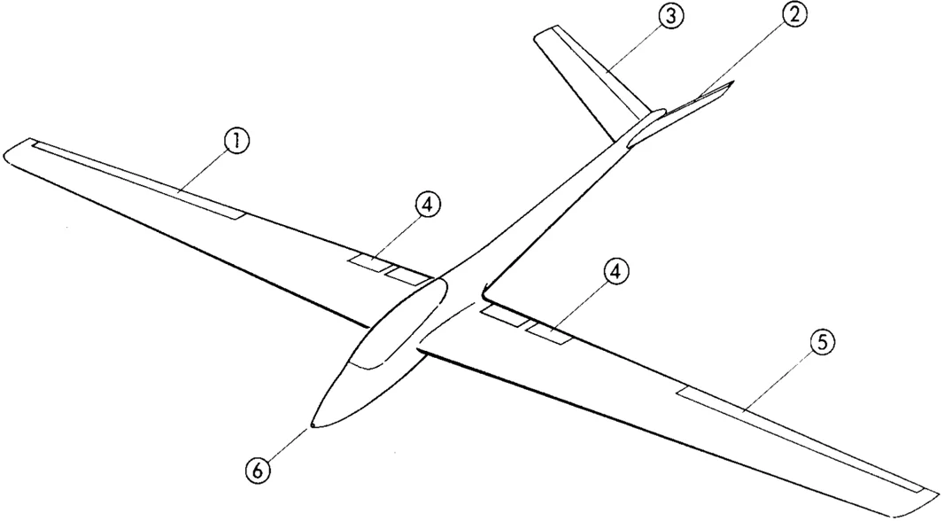
The "Salto" is an example of a model with a V-tail. At the inboard end of each wing are 2 rotating trailing edge spoilers, which are used to lose height and to control the landing approach. The ailerons are operated by two servos, with "electronic" differential. They are also set up as "flaperons", i.e. they can be moved in the same direction to act as camber-changing flaps. As flaperons which do not reach to the wing root have inherent aerodynamic disadvantages, the "flap input" should be kept small, and they should only be used for aerobatics to improve manoeuvrability. For this reason the flap input can be switched off by means of the switch S3. The flaps and the spoilers are mixed with the elevator, to provide automatic pitch trim compensation.
Summary:
Switches: S1, S2 for Dual Rates on AILERON, ELEVATOR; S3 switches the flap input to the ailerons Note: when adjusting the mixing inputs it can be very useful to switch off any mixing inputs which are not needed for the moment Possible modifications: Control of the FLAP input via stick instead of slider Use of Combi-Switch (controlled via S5).