If you have followed these instructions carefully, all the correct roll-axis and pitch-axis movements will now be available on your model.
- If you require virtual rotation of the swashplate for your helicopter, select the PHASE input for one of the rotor head servos. Switch the input ON (input field ☑ and key [R]), move to the Degree input field with ☑, and set the desired swashplate rotation. If you hold the pitch-axis or roll-axis stick to one end-point, you will be able to see the change clearly.
4-point linkage "HEAD-MIX"
The 4-point linkage is becoming increasingly popular. Even if one servo fails completely, the helicopter remains controllable, and can be "saved".
We assume that you are at the Status display. Move to Menu 1 with the [M] key, then on to Menu 2 with the ☑key, on to ASSIGN and finally to SERVO.
Assign the servos as follows: Servo No. 1 controls HEAD-MIX Servo No. 2 controls HEAD-MIX Servo No. 3 controls HEAD-MIX Servo No. 4 controls HEAD-MIX
Once more, to remind you: Release the SERVO input line with the selector key ☑. Select the servos in turn with the [+] or [-]keys. Release the Controls field again with the selector key ☑, and select HEAD-MIX with the [+] or [-] key. Repeat the process with the second servo, and so on.
After you have assigned the rotor head servos, return to Menu 1 using the [M] key and branch again to SERVO ADJUSTMENT. Select Centre, and set the servo centres. Check here that the trim sliders and the transmitter controls are set to zero (0%).
Return to the "Servo Adjustment" menu with the [M] key, then branch to TRAVEL + REVERSE with the selector key ☑.
Important:
- It is essential that you set the direction of rotation of the collective pitch inputs to the head servos first.
Operate the collective pitch stick, and watch the rotor head servos.
Check carefully which servo or servos rotate in the wrong direction. Select the servo concerned, then the Collective Pitch input, and release the input field (selector key ☑). Press the [R] key to reverse the direction of rotation of that input.
- Select the GEOMETRY input of all the rotor head servos in turn, and set the position of each servo in degrees. Switch to the input field using the selector key ☑, and switch GEOMETRY "ON".
The right-hand servo should be 90 degrees, the rear servo 180 degrees, the left-hand servo 270 degrees, and the front servo 0 degrees.
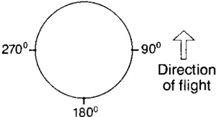
If you have followed these instructions carefully, all the correct roll-axis and pitch-axis movements will now be available on your model.
- If you require virtual rotation of the swashplate for your helicopter, select the PHASE input for one of the rotor head servos. Switch the input ON (input field ☑ and key [R]), move to the Degree input field with ☑, and set the desired swashplate rotation. If you hold the pitch-axis or roll-axis stick to one end-point, you will be able to see the change clearly.
3-point linkage, 120-degree "HEAD-MIX"
The 3-point, 120-degree linkage is the most popular arrangement.
We assume that you are at the Status display. Move to Menu 1 with the [M] key, then on to Menu 2 with the ☑key, on to ASSIGN and finally to SERVO.
Assign the servos as follows: Servo No. 1 controls HEAD-MIX Servo No. 2 controls HEAD-MIX Servo No. 4 controls HEAD-MIX
Once more, to remind you: Release the SERVO input line with the selector key ☑. Select the servos in turn with the [+] or [-]keys. Release the Controls field again with the selector key ☑, and select HEAD-MIX with the [+] or [-] key. Repeat the process with the second servo, and so on.
After you have assigned the rotor head servos, return to Menu 1 using the [M] key and branch again to SERVO ADJUSTMENT. Select Centre, and set the servo centres. Check here that the trim sliders and the transmitter controls are set to zero (0%).
Return to the "Servo Adjustment" menu with the [M] key, then branch to TRAVEL + REVERSE with the selector key ☑.
Important:
- It is essential that you set the direction of rotation of the collective pitch inputs to the head servos first.
Operate the collective pitch stick, and watch the rotor head servos. Check carefully which servo or servos rotate in the wrong direction.
Select the servo concerned, then the Collective Pitch input, and release the input field (selector key ☑). Press the [R] key to reverse the direction of rotation of that input.
- Select the GEOMETRY input of all the rotor head servos in turn, and set the position of each servo in degrees. Switch to the input field using the selector key ☑, and switch GEOMETRY "ON".
The right-hand servo should be 60 degrees, the rear servo 180 degrees and the left-hand servo 300 degrees.
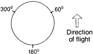
If you have followed these instructions carefully, all the correct roll-axis and pitch-axis movements will now be available on your model.
- If you require virtual rotation of the swashplate for your helicopter, select the PHASE input for one of the rotor head servos. Switch the input ON (input field \square and key \text\textcircledR), move to the Degree input field with \square, and set the desired swashplate rotation. If you hold the pitch-axis or roll-axis stick to one end-point, you will be able to see the change clearly.
This setting-up procedure produces the program required for your model. You can now set up the travels according to your own experience or the information provided by the helicopter manufacturer. Use an angle jig, or check the settings by eye.
How to set up and use the Teacher/Pupil system
 Teacher/Pupil operation (sometimes known as the "buddy-box" system) is the best method of learning to control a radio-controlled model, from the point of view of model longevity. "Teacher" and "Pupil" have one transmitter each, inter-connected by the Teacher/Pupil lead, Order No. 8 5121. Only the teacher's transmitter radiates an RF signal. The pupil's transmitter generates a signal, but it is not broadcast at Radio Frequency; instead it is transferred to the teacher transmitter through the cable, where it is "processed".
For this reason it is vital that only basic signals come from the pupil's transmitter – no mixed signals at all! If mixed signals are sent to the teacher's transmitter, these signals would be processed twice.
Assign the transmitter controls of the pupil's transmitter as follows: e.g. A controls aileron B controls throttle, etc. and continue: Servo No. 1 controls aileron Servo No. 2 controls elevator, etc.
If you are using a different transmitter, e.g. ROYAL mc, be sure to switch all mixers "OFF" at the pupil's transmitter.
The pupil's transmitter does not require an RF module. However, if one is fitted, it is automatically switched out of circuit when the lead is plugged in.
The teacher's transmitter has to be fitted with a Teacher/Pupil switch, by means of which he can alternate between "pupil has control" and "teacher has control", and can therefore intervene whenever danger threatens.
Teacher/Pupil operation is basically restricted to the four main stick functions (more than this is unnecessary, and is not recommended in any case).
One special advantage offered by the PROFI mc 3030 transmitter is that individual control functions – e.g. just rudder, or just rudder and elevator – can be transferred, so that the pupil can "learn the ropes" in easy stages.
We will assume from now on that the PROFI mc 3030 transmitter is the "teacher" unit.
The following types can be used as the pupil transmitter:
Naturally, other PROFI mc 3030 transmitters; any other MULTIPLEX transmitter which is fitted with a "diagnosis" (closed loop, or direct servo control) socket.
These include "ROYAL mc"; "COMBI" and "COMBI 90", Cockpit" and "EUROPA-Sprint".
The teacher transmitter must be fitted with a Teacher/Pupil switch.
The following types of switch can be used: ON/OFF switch, long toggle Order No. 7 5698 ON/OFF switch, short toggle Order No. 7 5697
The best locations for "quick access" to the switch are bays 1, 7, 6, 12 (see page 6). The plug from the switch must be connected inside the transmitter to the "L/S" connector; see page 7. It does not matter which way round you insert the connector, but make sure that the switch itself is the right way round. This is explained on page 77 under "Testing the transmitter controls".
The two transmitters are inter-connected by the Teacher/Pupil lead, Order No. 8 5121. The lead is simply plugged into both transmitter charge sockets.
Caution: The ROYAL mc Co-Pilot lead Order No. 8 5122 cannot be used!
1. Essential adjustments to the Pupil transmitter
a.) If it is not a PROFI mc 3030 transmitter Set the transmitter to "PPM" transmission mode (assuming that it has two transmission modes). Switch off any mixers, Dual Rates etc. which may be in force. Set all the transmitter stick trims to centre. At this point you should also check which servo numbers (= channel numbers) are controlled by the transmitter sticks. To do this, operate the sticks and check at the receiver which servo moves and which receiver output it is connected to. Note down these four channel numbers; you will need them later when setting up the Teacher transmitter. It is not necessary to reverse the transmitter controls, or swap plugs over. Similarly it makes no difference whether the pupil, for example, flies "aileron (helicopter: roll) right" or "left"; the same applies to "throttle (collective pitch) right" or "left". These individual preferences are taken care of later when the Teacher transmitter is set up.
b) For PROFI mc 3030 transmitters: Here the setting up procedure is simple; you just need to set the transmitter to "Pupil mode". To do this move to the "Pupil" menu, with the key sequence M□□□ You will see the following display (the top line is only an example):
10 BIGLIFT PPM9 PUPIL MODE WITHOUT TRIM IS OFF
Press \square and then \boxR. "OFF" is replaced by "ON". That's all there is to it. Leave the menu and return to the Status display with \boxM\boxM\boxM\boxM.
When you wish to return to "normal flight operations" later, switch back in exactly the same way.
In the top line of the display the model name and "Pupil" will flash alternately. This is the transmitter's way of telling you that it is in "Pupil mode". This mode is maintained until it is switched out again – even if the transmitter is switched off in the meantime.
Here again, you will need to check which servo (channel number) operates which control function. You can find this information in the "Assign servos" menu; there you will find something like this:
"Servo No. 3 controls RUDDER"; "Servo No. 2 controls ELEVATOR", and so on.
2. Essential adjustments to the Teacher transmitter
Here things get a little more complicated; the PROFImc 3030 transmitter gives you so many options that you are forced to choose between them:
You can in fact arrange the sticks of the teacher and pupil transmitters in a different layout. For example, the pupil can fly "aileron left", and the teacher "aileron right"; neither needs to depart from his usual ways.
Even this is not so terribly difficult to set up; all you need to know is how your pupil usually flies.
There is a special menu for these adjustments in the Teacher transmitter: the "Teacher" menu.
You reach this menu with the key sequence \boxM\square\square\square. You will see this menu:
10 BIGLIFT PPM9 PUPIL TO TEACHER \rightarrowAILER \rightarrowSPOIL \rightarrowRUDD \rightarrowELEVA
Note: The "arrangement" and type of the four main stick functions in this menu are based on the model which has been selected as the "Teacher" model. The menu may therefore look slightly different in some cases. For example, the ailerons may be in a different "corner"; if the model is a helicopter the control functions will appear as collective pitch, roll, pitch and yaw.
Now you have to tell the transmitter which channel (= servo) numbers of the pupil's system are to be taken over by the 4 main control functions.
For example, press the \square key. The slash sign (/) before "\rightarrow AILERON" starts flashing.
If you now press the \boxplus key, the slash is replaced by a "1"; press again, and it becomes "2", etc. This means: Channel 1 (or 2, etc.) in the pupil transmitter will be taken over as the aileron signal in the teacher transmitter, and "replaces" the teacher's aileron stick.
If you leave the slash unchanged, nothing will be taken over, and control of ailerons remains with the teacher.
If it turns out that the control function is reversed when the pupil is in control, simply press the \boxR key while the channel number is still flashing. The "\rightarrow" arrow will be replaced by a white arrow on a black background (inverse video); this indicates that the direction of rotation is reversed when it is "taken over".
Assign the remaining three control functions in the same way.
The four "arrow keys" are each used to activate one of the four control function assignments in the menu.
Caution: When trying out the system, do not forget to set the Teacher/Pupil switch to "ON"; otherwise the system won't work at all!
And by the by ... It is vital to determine first which channel number on the teacher's transmitter controls which function. Alternatively, you can just try everything out when you set up the system.
(Although in that case you would not really "understand" what was going on).
We recommend that you practise these adjustments several times before you go to the flying field. At the take-off strip you will not find the atmosphere quite as peaceful as in your workshop. You will undoubtedly have to change something or other at the flying site, for example, when you want to transfer more or fewer control functions to the pupil.
75
The Reserve Battery System
Aids to testing
"Personalising" your transmitter
The Reserve Battery System
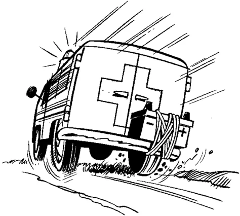
Many car drivers, despite having a large fueltank and an accurate fuel gauge, carry a reserve fuel can in their car: getting stuck with an empty tank is unpleasant, and can be dangerous. If your transmitter "runs out of juice" while you are using it, then that is rather worse than unpleasant: it usually means the loss of the model, not to mention other dangers. The reserve battery is a form of safety net to guard against such nasty surprises. It gives you a solid reserve operating period of about 15 minutes. That is enough to get any model safely onto the ground in one piece.
How it works
The reserve battery is automatically charged up whenever the main battery is recharged, through a special electronic circuit. It cannot be overcharged. In fact, you never need to think about it at all under normal circumstances. If the voltage of your main transmitter battery falls to the danger point and the audible monitor signal sounds, then you can select your "utterly certain" safety system, by manually switching to the reserve battery. We chose this method of switching deliberately. The monitor lamp will flash for all the time the transmitter is switched to the reserve battery. Because of the flashing lamp you are bound to be aware that the transmitter is being supplied from the reserve battery, if you switch on again later, for example.
Charge current and charge period
The automatic charge circuit for the reserve battery bleeds off a current of about 30 mA from the charge current which is supplied to the transmitter. As most chargers produce a constant current, the main transmitter battery is deprived of that 30 mA, and you should therefore charge for longer than normal. The charge period should always be calculated from the residual current which is fed to the main battery. Here is an example: Current from charger = 200 mA. Charge period increases by 30/200 = 0.15 = 15% If you have a charger with switchable or selectable current ranges, you can, of course, increase the charge rate by about 30mA, and your normal charge period will be unchanged.
Rapid-charging
The reserve battery is always charged at the "normal" current, i.e. at the 14-hour rate – even if you rapid-charge the main battery. If you slow-charge the main battery in the normal way, then the reserve battery will always be fully charged. However, if you usually use a rapid-charging technique, it may happen that the charge period is not sufficient to compensate for the self-discharge tendency of the reserve battery. This is more likely at high temperatures, or if you do not use the system for a considerable time. For this reason always give a slow charge every 10th cycle – which you ought to do in any case for other reasons. If you have cause to use the reserve battery, you must slow-charge the battery at least once before using it again.
Installation
Switch the transmitter off, then open the back and place it inverted on the workbench. The next step is to withdraw the battery cradle from the transmitter case, which is now facing you. Pull it upwards carefully, holding it at both ends (see Fig. 42).
 Fig. 42
 Fig. 43
Place the reserve battery unit in the bottom right-hand corner, over the mounting eyes provided for it, and retain it with the 4 screws and eyelets supplied (Fig. 43). Caution – make sure the eyelets are the right way round (Fig. 44).
 Fig. 44
 Fig. 45
Select one of the switch bays (we recommend bay 10), cut away one of the holes completely and install the change-over switch. Deploy the connecting cable from the switch to the battery as shown in Fig. 45. Take care here, to avoid damaging or jamming any of the wires. Once you have checked that the wires are deployed exactly as shown in Fig. 45, especially where they run around the main battery, and that they cannot get tangled, replace the cradle and main battery (the lugs in the cradle must be connected to the mounting eyes in the casing).
76
Now you have to complete the connection between the reserve battery unit and the transmitter electronics.
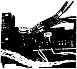
Fig. 46 Fig. 47
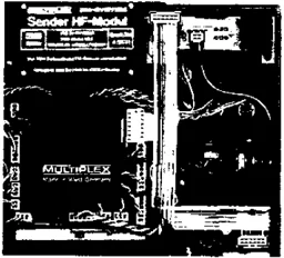
To do this, please refer to Fig. 46. First pull out the bridging plug adjacent to the RF module; it is no longer needed. A ribbon cable is supplied in the set: insert one of the two plugs (either will do) on the ribbon cable into the vacant socket. Now bend the ribbon cable as shown in Fig. 47 and deploy it as shown. Insert the plug into the socket on the reserve battery unit. It is not possible to connect this with reversed polarity, but please refer to Fig. 47 in any case. Now check everything one last time. Convince yourself that the ribbon cable cannot obstruct the stick mechanics, and you are done. Close the transmitter. From this time on please be sure to slow-charge your transmitter as often as possible, so that you can be sure that the reserve battery is fully charged.
The "Servo Test" menu
This menu allows you to "move" a servo or group of servos automatically, to check their operation. This can be useful for range tests, or for checking that servos are running smoothly. Servos are selected according to the transmitter control or control function, rather than by their receiver output number. For example, if you select "Aileron", all the aileron servos will run. In the test the servo or group of servos runs slowly to and from one end-point to the other. If the servos are involved in a mixing arrangement, they only move over the arc dictated by the mixing ratios. In short: When the test is invoked, the servos respond as if you were slowly moving the corresponding transmitter control to and fro by hand. How to carry out the "test run" From the Status display you reach the "Servo Test" menu with the key sequence M ▮▮.
You will see a display similar to this:
12 CORTINA PPM9 -- SERVO TEST -- CONTROL: UNUSED STATE: OFF
Press the ▮ key. "AILERON" starts flashing. You can now "leaf through" with the ⊕ and keys, and select the function you want. Once selected, press the ▮ key and "OFF" in the 4th line will flash. Press the Ⓡ key, and "OFF" is replaced by "ON". All the servos which respond to that function will now start running. To end the test run, press Ⓡ again; the status will return to "OFF". Leave the menu with M in the normal way. If you switch your transmitter off at any time, the test procedure is automatically halted.
The "Transmitter Control Test" menu
All the sliders and switched functions must be installed in a particular orientation. If they are installed the wrong way round, the aids to adjustment in the menus will be incorrect. You will be aware by now that the transmitter only "recognises" the sliders and switches under their abbreviations E - I, S1 - S5 and LS, while you undoubtedly prefer to remember their English descriptive names. This menu is used to do two things:
- You can establish whether the sliders and switches are installed the "right way round", and/or connected to the main circuit board correctly. This is only usually in question when you install extra switches, but it also applies if you wish to relocate the switches to suit your personal preference.
- You can find out quickly, and without opening the transmitter, where any particular switch (which you know by the designation printed on the sticker) is plugged in at the main circuit board, i.e. under what designation the transmitter "knows" it. But first a minor correction: the term "transmitter control" test is not quite accurate, because you cannot test the two transmitter stick units – simply because there is no need to do so.
In fact, this menu can be used to test all the switches, i.e. even those which are not strictly "transmitter controls". You will recall (page 14) the following: Transmitter controls "move" something on the model directly: sticks and sliders are typical transmitter controls. But switches can also be transmitter controls if they are connected to "transmitter control" connections, or letters – inputs A - I (e.g. a switched channel switch – G or H). There are also coupling and change-over switches, which include Dual-Rates switches and the Teacher/Pupil switch. They are designated S1 - S5 and LS. Finally there is the "Memory" change-over switch, which has its own special function (see page 80), and which belongs to neither group. It is designated "M". Now we have jogged your memory, back to business: The TEST menu is under the "ADJUST TRANSMITTER CONTROLS" menu. From the Status display, you reach it with M and ▮. Select the point TEST with the ▮ key. You will see the following display (the arrow directions do not concern us for the moment):
77
SW1 2 3 4 5 L M+ ↑ ↑ ↑ ↑ ↑ ↑ 0 CTRL: E F G H I MDG = ↓ ↑ — — —
Lines 1 and 2: In line 1 you will see the "names" of the coupling and change-over switches; the "M+" at far right stands for the "Memory" switch. Operate the aileron Dual-Rates switch (far left): the arrow under "S1" will reverse. This should tell you two things:
- The aileron Dual-Rates switch is connected to "S1".
- If the direction of the arrow and the position of the switch toggle are the same, then the switch is installed correctly. Try the same with the other Dual-Rates switches and the Combi-Switch. You should find this arrangement: Dual Rates aileron = S1 Dual Rates elevator = S2 Dual Rates rudder = S3 Combi-Switch = S5 This is the "factory-standard" switch arrangement (although you do not need to keep to it – see page 38). The arrows under S4 and L (short for LS) cannot be reversed, since nothing is connected to these inputs as standard. When you operate the Memory change-over switch the "0" (centre position of switch) should change to a "1" or a "2".
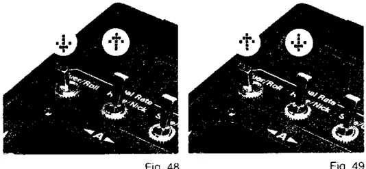
Fig. 48 Fig. 49
If you subsequently fit another switch, or move an existing switch to a new location, it may be that the arrow direction and the position of the switch toggle are not the same. In this case you must turn the switch itself round. Don't reverse the plug at the circuit board – that has no effect!
Now to lines 3 and 4: In line 3 you will see the transmitter control designations E - I; under each one, in line 4, either an arrow or a horizontal line. If you move the left-hand slider forward, the arrow under "E" should also point forward (up). When you move the slider back, the arrow should reverse. If you move the slider slowly around its centre point, you will find a position at which the arrow is replaced by a horizontal line. This is the exact "electrical" centre point. Component tolerances may result in this position being slightly different from the scale printed on the transmitter, but in practice this makes no difference. If no transmitter control is connected to one of the control inputs (G, H, I as standard) then this horizontal line will appear there at all times. If a transmitter control is fitted the wrong way round, i.e. the direction of the switch toggle is not the same as the direction of the arrow in the display, then reverse its plug at the main circuit board. Please note this difference between the transmitter controls and the other switches, as described above!
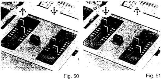
Fig. 50 Fig. 51 It is quite difficult to describe these checks, but you will find that they only take a moment to carry out!
"Personalising" your transmitter
Your name in the display Your name can be entered in the bottom line of the LCD display, and it will then be on show there all the time, unless you invoke the stopwatch or the rev counter. However, you cannot enter your name yourself; it has to be done by the MULTIPLEX Service Department, or by a specially trained dealer.
09 FIESTA PPM9 7.71V OP.TIME 03:32 ROGER PILOT
This is a useful feature for identifying your transmitter, and for deterring thieves.
If you would like this done, please contact your dealer or the MULTIPLEX Service Department.
The sticks The transmitter is supplied with 3 pairs of stick ends: short, medium-length, and long. Each one can be adjusted in length by about 10mm. Select the length which suits your preference. To adjust or change the stick end, rotate the grip until you feel it "unlatch", then adjust the length or pull it off altogether. Slip the new grip into place, set it to the required length, then turn it through about 180 degrees (Fig. 52).
Stick press-button The long and medium-length stick ends can be fitted with a press-button (momentary contact), as shown in Fig. 53. This can then be used either as a "transmitter control" or as a reversing or coupling switch.
78
 Fig. 52 Fig. 53
Using the press-button: As a transmitter control: actuating a tow-release mechanism As change-over/coupling switch: operating the stop-watch
Stick switch It is also possible to fit an ON/OFF switch to the stick end. The advantage of this form of switch is that you can see and feel the current position of the switch at any time. Applications: Fixed wing: flap switch tow release Helicopter: auto-rotation switch The press-button and switch can only be installed by the MULTIPLEX Service Department. Please contact us if you want the job done; addresses are in the appendix.
Re-locating or installing switches The switches and their location on the standard transmitter have been chosen carefully to meet most modellers' practical requirements. However, you are free to move the switches to suit your own preference. The transmitter is supplied with two blank switch panels and legend sheets to help you. Additional switches are available in several versions. If you wish to rearrange the layout of your transmitter, please bear in mind the following points: The Digi-Adjustor can only be fitted in switch bays 1, 2, 5 and 6 (see page 6); its mounting bracket obstructs one adjacent switch bay. If you have switches with a short toggle installed, other switches with a long toggle should only be fitted in the row furthest from you. If you want to change the switch layout you must first remove the existing switches; undo the knurled nuts using the special spanner supplied with the set. If you want to re-locate the Digi-Adjustor, undo the grub screw and remove the rotary knob. With the switches removed, you can press the existing switch panel out of the transmitter from the inside, by squeezing its central snap fixing and pushing it out. If you wish to change the position of the Digi-Adjustor, you must remove the switch panel first. Please note that the washer on the fixing screw is not symmetrical, as the spacing of the switch bays in the right/left direction is different from the fore/aft direction. Turn the washer as necessary, and check that the shaft of the Adjustor is central in its hole. The fixing screw can be re-tightened when this is the case.
It is best to cut out the holes you need in the new switch panel before you install it in the transmitter. As the plastic is much thinner at the hole positions, this can easily be done with a sharp, pointed-blade modelling knife. Caution: the switch panels only fit one way round – take care not to cut out the wrong holes! If necessary, the MULTIPLEX Service Department will help you out with a new panel. Install the switch(es). Before tightening the fixing nut permanently and deploying the connecting leads, run through the "Transmitter Control Test" (see page 77), to ensure that the switches are installed the right way round. You will find more details about switches on page 7 ("Connectors on the main electronics circuit board") and page 14 ("Transmitter controls and switches"). The final job is to apply the self-adhesive stickers in the depressions next to the switches. Remove each sticker in turn, using a pair of tweezers or fine-nosed pliers, place it in the depression in the switch panel, and press it down firmly (Fig. 54). If we have not provided a sticker printed with your particular application, use the all-yellow stickers and write the inscription with a felt-tip pen.
 Fig. 54 Fig. 55
Hand supports, weather shield If you want to use the transmitter as a belly-mounted unit, hand supports with integral folding neckstrap bars (Fig. 56) are available. The supports are screwed to the sides of the transmitter.
 Fig. 56
For further details, please refer to the instructions supplied with the hand supports. A weather shield is in preparation at the time of printing this manual.
For Experts
Switching memories "in flight"
This new, powerful facility is one further important step towards everybody's "dream radio control system".
The principle is very simple: For one and the same model you provide two (or even three) separate memories. The "lists" stored in them are different. You can then switch between the different lists (or memories) at any time.
The differences between the lists can be as small or as great as you think fit – the scope of this feature is really limited only by your imagination. For example, the two lists could share the same "basic configuration", but have quite different adjustment values. On the other hand, you might wish to have a totally different list that you can call up.
For example, imagine a glider with a complex wing flap system. You could provide a "tow launch configuration", a "normal configuration" and a "speed configuration". The different configurations would have different movements of different pairs of control surfaces, and control surface throws would also be different. Fans of the flying wing layout will now be pricking up their ears.
Incidentally, such "configuration modifications" are also used in full-size aviation; "fly by wire" technology is the key there.
One further important application is "inverted flight switching" for a helicopter. In this case several control effects and basic adjustments have to be changed simultaneously.
The solution is obvious: one memory for normal flying, and one for inverted flight. Previous transmitters have always struggled with this problem, as so much has to be changed. In the case of the PROFI mc 3030 you can create a more or less completely "new" list for inverted flight, and there are virtually no restrictions on what you can do.
And now to practice: There is little we can say specifically about the "second" or even "third" list; it all depends on your particular application. If you aim mainly at changing a few settings, then the simplest method is to copy the "starting list", then change the appropriate values. In other cases it may be necessary to create an entirely new list. Bear in mind that you are free to change every aspect of the second list, including modifying the mixers, re-defining the change-over switches, and so on.
One important condition: the memory to which you wish to change must be the next higher one in sequence, or – in the case of two alternative lists – the next-but-one in sequence.
Example: the "normal" memory for the model is No. 11. You can then change to No. 12 and No. 13.
You actually change memories using the "Memory" switch. If you move to the "Transmitter control test" (see page 73), the screen will show the memories to which you can switch in each position. At one end-point of the switch you will see the display "M+1", in the other "M+2".
In our example "M + 1" would be memory No. 12; "M + 2" would be memory No. 13.
You may have to copy the contents of your memories to adjacent locations, in order to be able to switch between them.
Now there is one more safety feature to be overcome. If you could switch between one memory and its neighbour too easily, then one accidental movement of the switch would be fatal. For example, if the model in the adjacent memory happened to be entirely different from the one you were currently flying.
For this reason we have determined that the name of the model must end (eighth character) in a number, if that memory is to be selectable in flight. Only then is it possible to switch between them.
Example: Memory No. 7 contains "CORTINA1". If the model in memory No. 8 is "CORTINA2", then it is possible to switch between them. If Memory No. 9 contained "CORTINA3", then you would also be able to select that memory in flight.
If you try to switch memories without naming the lists in this way, you will just hear a brief beep when you operate the Memory Switch.
Three further tips on this subject.
- In the example above you could use the names "CORT-TL1" instead of "CORTINA1", "CORT-NF2" instead of "CORTINA2" and "CORT-HS3" instead of "CORTINA3".
In this case TL stands for tow launch, NF for normal flight, and HS for high speed. The names will then remind you of which list serves which purpose. The final numbers must remain; but they are not very informative on their own.
-
If you change memories in the "normal" way from the keypad, please check that the Memory Switch is in the "basic" position. Otherwise the following will happen: you want to change to, say, Memory No. 13. Let's suppose that it contains a model list which you have set up as a "switchable" one. If the Memory Switch is in the wrong position, the transmitter immediately changes to the new memory, and instead of No. 13 you end up at No. 14 or No. 15. This can lead to considerable confusion.
-
Please don't use this feature for "simple" switching tasks; it always "costs" you one or two memories. For example, you could execute a simple change of camber-changing flap by switching memories; but it is just as easy to use the "Fixed Value" from the Transmitter Control options, and this alternative would not swallow up another memory.
80
Servo assignment for wings
with more than two control surfaces.
On page 33 we discussed the "traditional" assigning process for the aileron servos of models with wings featuring separately controlled, electronically differentiated ailerons. The recommended assignment is as follows:
Servo No. 1 = Aileron 1 Servo No. 5 = Aileron 2
For wings which have more than 2 control surfaces, all of which act as (mixed) ailerons, and all of which are to feature differential movements, this assignment can no longer be used.
Example: "Quadro-flap" arrangement (see page 91). In such cases the servos must be assigned "in sequential pairs".
An example will make this clear:
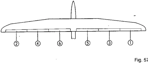
Fig. 57
In the drawing we show an "extreme" wing layout, with 3 control surfaces per wing, all of which are to work as ailerons, and all of which require differential movement.
We have already explained how you control the six servos (with the "QUADRO" mixer); we have also discussed selecting and adjusting the "Differential" option. Now all that remains is the order of the six servos at the assignment stage.
In our example, assigning "in sequential pairs" works out like this:
Servo No. 1 controls QUADRO | Outboard pair Servo No. 2 controls QUADRO } of control surfaces
Servo No. 3 controls QUADRO | Centre pair Servo No. 4 controls QUADRO } of control surfaces
Servo No. 5 controls QUADRO | Inboard pair Servo No. 6 controls QUADRO } of control surfaces
This should make everything clear. If you have only two servos per wing panel, (normal Quadro arrangement), simply stop at No. 4.
If you do not keep to this sequence, differential aileron movement will not be correct.
The "Gx" switch
What might that be?
When assigning switches you are bound to have noticed that an extra switch is offered in addition to the "normal" switches S1 - S5 and L/S: if you are setting up an empty memory for the first time, this switch is designated "H".
In the standard designation "Gx" the "x" stands for the letters A to H. This might lead you to suspect that it has some connection with the transmitter controls, which also have the designations A to H.
And that's exactly right. The "Gx" switch does not exist in hardware form – it is a "software" switch – but it works in exactly the same way as a "normal" switch. You can assign this switch to any one of the transmitter controls A to H, and it then works in the following way:
If the associated transmitter control is set to one end-point, then the switch turns ON. It stays ON (even though the control is moved away from its end-point) until the transmitter control is moved to the opposite end-point. It then switches to OFF.
This sequence can be repeated ad infinitum: the switch comes ON again when the control is moved back to the first end-point, etc. (for the technically minded: extreme switch hysteresis).
But there's more yet! Gx can also be used as a momentary switch, as follows:
- a fixed switching threshold is assigned to the Gx switch (between 5% and 95% of the transmitter control value).
- If the associated transmitter control is moved past the switching threshold, then the switch is ON (transmitter control below threshold = OFF). When the Gx switch is in use, its effect can be reversed (as for any other switch) with the Ⓡ key.
Before we consider the matter further, a little more on the designation of the switch. If you assign this software switch to, say, transmitter control B, then its name becomes "GB"; if you assign it to control D, then it is called "GD", etc.
How to assign "Gx" to a transmitter control
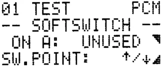
You will find the sub-menu "Gx" under the "Assign" menu. For your first experiment, move to this menu. You will see a display similar to this:
01 TEST PCM -- SOFTSWITCH -- ON A: UNUSED SW.POINT: ↑/↓
Press the ▣ key and leaf through with the ⊕ and ⊖ keys. The transmitter controls will appear in the sequence A to H, with the control functions to which they have been assigned. We will assume that you stay at "D: THROTTLE", and then leave the menu with the Ⓜ key.
You have now assigned "Gx" to the throttle channel, and from now on it will be called "D".
If you now move to the "TIMER" menu and select the stopwatch operating switch, as described on page 16, you will find "D" offered amongst the other options.
Select it!
Effect: when you apply "full throttle" the stopwatch starts running; when you close the throttle fully, the stopwatch stops.
We will assume that you don't want the timer to be controlled only by full throttle and idle. To change this, press the ▣ key, and use the Digi Adjustor to select a
81
switching threshold between 5% and 95% (3% steps). This allows you (for example) to set the timer switching point exactly to the threshold at which the electric motor starts and stops running.
You may think that this example is not all that useful, but it does show the principle, and it gives an idea of just how versatile your transmitter is. You can use the "Gx" switch anywhere where you could use the switches S1 - S5; e.g. as a Dual Rates switch, as a coupling switch, and so on.
Sample applications With an electric-powered model the motor is controlled by transmitter control B (MOTOR). The timer is controlled by "B". The stopwatch then stops automatically when you shut off the motor, thereby recording the length of the motor run.
On a glider you can couple the timer (e.g. in "countdown" mode) to the aero-tow release, or a (servo-operated) towhook. In this case, when flying a timed flight, you no longer need to worry about starting the stopwatch. If you assign "Gx" to spoilers or landing flaps, then you could automatically operate the Combi-Switch on the landing approach, or increase control surface throw, or switch out (or in) one mixing input or other. Bear in mind also that you can "reverse" the effect of this software switch, just like the other switches.
"Gx" is a completely new feature for radio control transmitters. Many likely applications are just waiting for you to discover them.
The "SI" switch
We have already mentioned the "SI" switch on page 42, in connection with the transmitter control options "Fixed Value 1" and "Fixed Value 2". You may have noticed already that "SI" is offered in the menus when assigning the switches S1 - S2.
What is "SI"? "SI" is another "non-hardware" switch, (i.e. a software switch), in this case coupled to the transmitter control input "I". However, it has different characteristics from the "Gx" switch described above:
Firstly, "SI" is a "three-position switch", i.e. it has an "idle position" in the centre, and a "working position" at both end-points.
If, for example, you connect a slider control to "I", and if the slider is set to centre, then "SI" is also at idle (OFF). If you move the slider to one end-point, then one side of "SI" switches on. If the slider leaves the end-point again, "SI" switches off immediately (note the difference from "Gx"! ).
At the other end-point of the slider the same applies; only in this case the other "side" of "SI" is switched on and off.
In this case "SI" has the same effect as if two end-point switches were fitted to the slider. With a little imagination you can use this feature for many interesting functions.
The main application of "SI" is rather simpler, however. In this case a "real hardware" 3-stage switch is connected to input "I"; for example Order No. 7 5699 (short toggle) or Order No. 7 5700 (long toggle).
If this "hardware" switch (actually a transmitter control in this application) is operated, then of course it operates the "software" switch "SI" as well. The final effect is a 3-position change-over switch, which can be used with the switches S1 - S5; but which has 3 positions; compare this with S1 - S5, which are only simple change-over switches.
And that is exactly what we need to switch between 2 different "Fixed Values"!
The main application of "SI" is in conjunction with the transmitter control options "Fixed Value 1/Fixed Value 2".
A further example will make everything clear: "camber-changing flaps with 2 switchable positions". We will assume that transmitter control E is assigned to the "FLAP" function. Move to the "Adjust transmitter controls" menu, and from there to "CONTROL E: FLAP".
Press the key, and leaf through to the "Fixed Value 1" option.
Press the key ("switch corner"), switch ON with the key, and then leaf through to "SI":
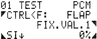
After pressing the key you can now set the first Fixed Value; for example, the "tow-launch" flap position.
While you are setting this up, operate the switch so that you can see the results of your efforts at the servo itself!
Now to the second Fixed Value:
Press the key again, leaf through with the key to the "Fixed Value 2" option.
You will see this display:
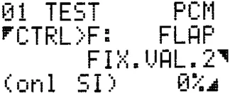
Press the key and you can adjust the other flap position (e.g. speed). Here again, operate the switch during the adjustment procedure (opposite end-point), so that you can see the effect directly.
Once you have finished the setting up process, the flaps can be controlled in the following way: Switch at centre: The flap servo is controlled by the slider.
Switch at the end-points: The flap servo runs to one or other of the pre-selected positions.
Transferring programs
between two transmitters
Let's imagine that you have worked hard at perfecting a list for your model "XYZ", and then one of your colleagues buys a kit of the same model. If he also possesses a PROFI mc 3030, you can share the fruits of your hard work with him by transferring a copy of your program to his transmitter. You may even find that your dealer, as a special service, will copy into your transmitter a suitable list for the helicopter he has just sold you.
Programs (model lists) can be transferred in either direction between two PROFI mc 3030 transmitters.
As you will see, this is a very simple matter. All you need is the transfer lead, Order No. 8 5120.
You can transfer in either direction: From your transmitter to another transmitter ("Export"). From another transmitter to yours ("Import").
First: "Export". Connect the two transmitters with the transfer lead, by inserting the plugs in the two charge sockets. Switch both transmitters on. If only one of the two transmitters is switched on, the display of the other transmitter will show "Rev count 000". This has no significance, and disappears as soon as the other transmitter is turned on.
As far as your transmitter is concerned, "transferring" is the same as "copying to another memory", so move to the "Copy Memory" menu (see page 47). Release the "Mode" with the key; then leaf through with the + key to the "EXPORT" mode.
The display will look something like this (lines 3 and 4 are just an example):
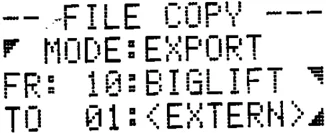
-- FILE COPY --- MODE:EXPORT FR: 10:BIGLIFT TO 01:<EXTERN>
Now you have to tell your transmitter which of its stored lists is to be transferred, and which memory in the other transmitter is to be used to store the copy. To do this press the key and then leaf through with the + and keys until you reach the memory number you want. For example, we will use "No. 12 CORTINA". Now enter the "destination" memory number for the other transmitter: press the key and leaf through again to the desired number. It makes sense at this point to check one last time that the selected memory in the other transmitter really is "empty", or that the contents can safely be overwritten; because what is there at the moment will be lost permanently after the transfer is complete.
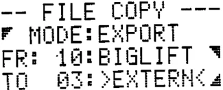
For our example we will nominate memory No. 3 in the other transmitter; that is where the program is to "arrive". Your display should now look like this:
-- FILE COPY --- MODE:EXPORT FR: 10:BIGLIFT TO 03:>EXTERN<
Everything clear so far? If so, press the M key, and you are done. The transfer is completed in a fraction of a second after you press the key. If you now look in the other transmitter (for instance, change memories), you will find "CORTINA" in memory No. 3. If the transfer does not take place for any reason (e.g. lead not plugged in, lead faulty, other transmitter not switched on), then your transmitter will show "Mode: - Error - " in line 2. Sort out the problem, then repeat the procedure.
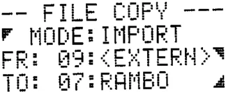
"Import" This is carried out in a similar manner, so we can deal with it in rather less detail. Instead of the "EXPORT" mode we select "IMPORT". In line 3 of the menu you have to enter which memory No. of the other transmitter contains the program to be imported. Example: No. 9. In line 4 your transmitter needs to know which of its memories the program is to occupy. We will suppose that No. 7 contains the model "RAMBO" at the moment, which is no longer of interest to us. It can be overwritten. Your display then looks like this:
-- FILE COPY --- MODE:IMPORT FR: 09:<EXTERN> TO: 07:RAMBO
The transfer takes place when you press the M key.
Two further points:
- If you should wish to interrupt an import, export, copy or delete process after you have started, simply switch the transmitter off briefly. The data in the model memories will then be unchanged.
- To ensure that import/export is possible between all versions of the transmitter, this function is only possible with memories 1 to 15 and Mx.
The FIXED VALUE virtual "transmitter control"
If you wish to operate a servo with a stick (or a function switch), you do not need to "lose" a transmitter control for the purpose. Assuming, that is, that all you need are two fixed servo positions.
Assign first: Move to the ASSIGN/SERVO menu with [M] [▲] [▼] [◄]. Select the servo you wish to use, press the [▲] key, and assign it to the FIXED VALUE "transmitter control". When you assign the "genuine" transmitter control, FIXED VALUE will not appear.
Set up as follows: Move to the ADJUST/SERVO/TRAVEL+REVERSE menu with the sequence [M] [▲] [▲], and select the servo which you have assigned to FIXED VALUE. Press [▲] and select the switch with which you wish to activate FIXED VALUE. Finally press [▼], and set the servo position for the first switch position.
The servo position for the second switch position is determined in the menu ADJUST/SERVO/CENTRE. To be able to do this, you must first go back by one menu level with the [M] key, and activate Centre adjustment with [▼]. Now move the physical switch to the other end-point, press the [▲] key, and set the desired second position for the servo.
The code lock
At the time your dealer enters your name, he (or the MULTIPLEX Service Centre) can activate a code lock. The code consists of four numeric digits (numbers) between 0 and 7. The keys on the keypad correspond to the figures shown in the diagram below.
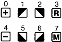
Once the code lock has been activated, every time you return to the top menu level (Status display) you will be asked whether you want to "LOCK" the transmitter or not. If you answer LOCK YES/NO with YES ([▼]), then every time you attempt to move to a menu, the display requests you to ENTER CODE. Thus the only persons who are able to make changes to your transmitter are those who know the right four keys to press.
Caution! If you switch off the transmitter with the lock open, it will still be open next time you switch on.
The MULTINAUT-plus system

This expansion system is intended principally for model boats which are fitted with a large number of auxiliary working systems. But even if you are a model aircraft flyer, it may well prove worth your while finding out what can be done with this system. Especially if your interest lies in large scale models. If it's going to be scale – then let's make a proper job of it! After all, the real thing has navigation lights, landing lights, an on-board starter, . . . Just imagine for a moment what could be crammed into such a model: For the basic functions you need four control channels. Add differential ailerons, and it's five. Plus retractable undercarriage, landing flaps, and steerable nosewheel. Now we're up to eight functions. You want to start your model's engine from the transmitter? Then you will need three further functions in addition to throttle: glowplug battery switch, start, mixture adjust. We're already up to 11 functions. And what about the towhook, the parachute eject system, navigation lights and landing lights? Suddenly we seem to need all of 15 functions. And no doubt you could think up a few more. But how are we to control all that? This is where the MULTINAUT-plus system comes in. It is an expansion system for transmitter and receiver. The minimum system consists of one transmitter control module and one receiver module, which is connected to the receiver in the same way as a servo. These two basic modules alone are enough to solve our problem: glowplug, starter, navigation lights and landing searchlights are connected directly to the four integral relays in the receiver module. Each relay can switch loads of up to 10 Amps; no problem there! Mixture adjustment and undercarriage are catered for with the two additional proportional functions.
A quick idea of how it all works
The additional control signals from the transmitter module travel to the receiver "piggy-back" style on one of the normal control functions. This function is therefore slower in transmission speed, but in practice this makes little difference, as we are only talking about fractions of a second. To prevent the risk of jerky servo movements, the MULTINAUT-plus receiver deliberately slows down and smoothes out the movement of servos connected to it. This can be ideal for certain functions, for example, for scale-speed flap extension; this is why we use one of the MULTINAUT-plus proportional channels for the flap function.
Incidentally:
There are four more switched channels available. Fit a relay expansion unit to the receiver module, and these can also be used for similar purposes. What will you use them for? Have you no imagination?!
 Fig. 58
 Fig. 59
Installation
The MULTINAUT transmitter module is installed in one of the two switch wells; it takes up all six of the switch bays on that side. Any switches already in place there will need to be shifted to the other side. More details are provided in the operating instructions supplied with the MULTINAUT-plus system.
The assigning procedure
After installing the module, you need to tell the transmitter which servo output at the receiver end the MULTINAUT receiver module is to be connected to. All you have to do is assign that servo function to "MULTINAUT". You also have to inform the transmitter which socket (G, H, or I) the MULTINAUT transmitter module is connected to. This is done under "SERVO: TRAVEL + REVERSE". Leaf through the list of servos until "MULTNAUT" appears. Next to "INPUT:" you will see G instead of the name of a control. Enter here the input to which the transmitter module is connected; it must be one of the inputs G, H or I. Now the transmitter module has to be switched on. Select the field below, and switch "OFF" to "ON". That's it.
And finally
If one transmitter module is not enough: just install a second one.
85
II. The receiving system
Connecting servos and batteries
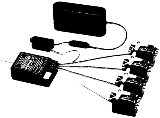
The receiver is the "heart" of the receiving system. Servos, motor controllers, switch modules and MULTI-NAUT-plus receiver modules are connected directly to it. The receiver battery is connected to the receiver via a "switch harness" (Fig. 60).
The receiver servo output sockets are numbered from 1 to a maximum of 10, depending on the number of servos which can be connected. Each servo output corresponds to one control function. For reasons of space, certain output sockets on the smaller receivers are combined, so that two servos can be connected to one socket. This type of socket is marked, for example, "8/9". Only one servo can be connected directly, and this is always the lower number; in this case channel 8.
What if you need both functions? In this case you need an expansion adapter (Order No. 8 5060), which consists of a plug and two sockets. The plug is connected to the receiver socket; the two servos are connected to the two sockets on the adapter (Fig. 61).
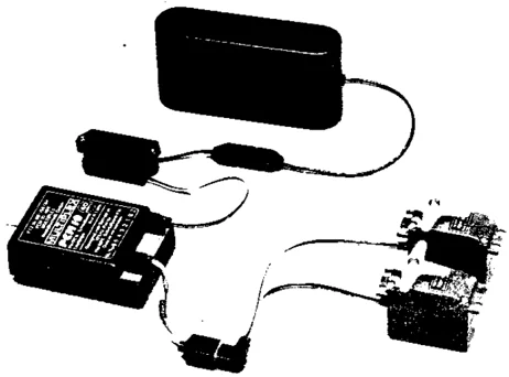
Fig. 61
The switch harness
This is plugged into socket "B". The switch incorporated in the harness is used to turn the whole receiving system on and off. The switch itself can be installed in the model's fuselage side. Switch harnesses are available in several forms; please refer to the main MULTIPLEX catalogue for details. Some versions are fitted with a separate socket for charging the receiver battery. On the switch harness supplied with the set (Order No. 8 5100) the charge socket is integral with the switch casing. This means that the battery can be recharged without having to open up the model (Fig. 62).
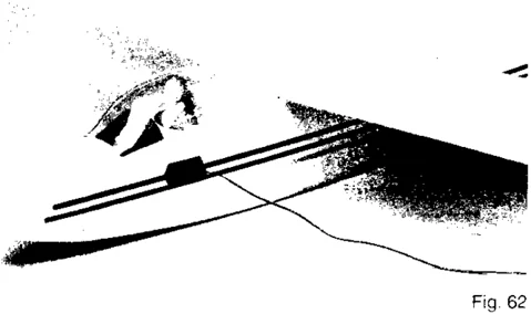
Fig. 62
PPM or PCM?
PCM (Pulse Code Modulation) is the more "intelligent" of the two transmission methods. In the case of PCM the information is encoded by the transmitter. The receiver is able to recognise interference, and continues to send the last "good" signals to the servos until it again receives a signal from the transmitter (see Fail Safe). Thus PCM eliminates servo jittering. On the other hand, this interference suppression can
86
lead to the PCM pilot failing to notice interference until much later than with a PPM system.
PPM (Pulse Position Modulation) still has the advantage if you require ultra-fast control response from your model, because the information is broadcast by the transmitter at a faster rate than by a PCM transmitter.
Which types of receiver can be used?
PCM All MULTIPLEX PCM receivers can be used with your new transmitter.
PPM When set to PPM, the transmitter broadcasts either 7 or 9 channels (see page 18 for method of switching). This means that you can use all MULTIPLEX FM PPM receivers (and all FM PPM receivers which can decode at least 7 channels) with this transmitter.
Fail-Safe ("emergency position" for servos)
Only available with PCM-DS receivers! After about 0.8 seconds of interference the throttle servo runs to the 25% position, and all the other servos are automatically reset to centre. Fail-Safe is a feature of the receiver, and must be switched on before it can work.
Single-superhet or double-superhet?
If you operate your model in the vicinity of a powerful VHF radio transmitter (frequency range 103 to 105 MHz), conventional radio control systems (single-superhet) in the 35 MHz band can suffer from interference. In technical terms: the powerful transmitter produces adjacent-channel interference to the single-superhet receiver. The double-superhet receiver utilises different technology which eliminates the problem altogether.
Arrangement of battery, servos and receiver
The diagram below shows the most favourable arrangement of the RC system components in the model. We recommend that you decide exactly how your system is to be installed in the new model before you start construction.
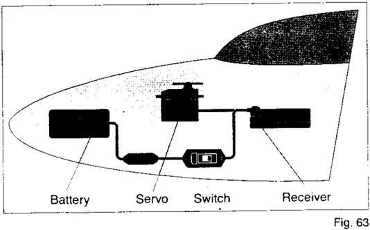
Battery Servo Switch Receiver Fig. 63
The receiver
When installing the receiver in the model, please observe the following points:
- Keep the receiver well away from powerful electric motors and electric ignition systems.
- Lead the receiver aerial out of the model by the shortest possible route.
- Protect the receiver from vibration by wrapping it in foam rubber and stowing it loosely in the model.
- Never alter the length of the receiver aerial.
- Deploy the receiver aerial in as straight a line as possible. Never leave it coiled up in the model.
- If your model incorporates carbon fibre reinforcements, do not deploy the receiver aerial inside the fuselage (signal screening).
- Do not stick the receiver aerial to any part of the model which is reinforced with carbon fibre (signal screening).
Range testing
Range testing can make a significant improvement to safety levels when you are operating your model. We have cooked up a standard recipe for range testing based on our own experience and measurements. If your system passes this test, you can be sure you are on the safe side.
- Collapse your transmitter aerial fully.
- Ask an assistant to hold your model about 1 m above the ground.
- Check that there are no large metal items (cars, wire fences etc.) close to the model.
- Make sure that no other transmitters are switched on (even on different channels) when you carry out the test.
- Switch on your transmitter and receiver. When the transmitter is 80 m from the model the equipment should be able to pass the following test:
- PPM system: the control surfaces should still respond immediately to stick movements, and make no uncontrolled movements at all.
- PCM system: the control surfaces should still respond promptly to stick movements. The inherent interference suppression of a PCM system prevents servos jittering. If the signal received is not strong enough, then a PCM receiver will continue to pass the last received signal to the servos. The servos will then either not respond to stick movements, or will hesitate before responding.
If your model is fitted with a motor, repeat the test with the motor running.
Interference suppression with magnetic/electronic ignition systems
- Screen the ignition lead with a metal tube, fixed (earthed) to the motor crankcase close to the ignition coil.
- Use screened plug connectors at all times.
- Never power the ignition system from the receiver battery.
● Keep a distance of at least 15 cm between the ignition system and all the RC system components (including the receiver battery). ● Keep the leads from the ignition battery and the other components as short as possible, and sufficiently thick (min. 0.5 sq mm). ● The ignition switch should be rated at a minimum of 10 A (minimum voltage drop).
Notes on servos
The servo torque for a particular control surface can usually be calculated with sufficient accuracy using the following rough formula:
0.75 x control surface area (in sq cm/100) = torque (in cm/kg).
In large models it is often necessary to extend servo leads. If you intend fitting extension leads, please note that they affect reception conditions. If the lead is more than 60 cm long you must use a separation filter. If other servo leads run parallel to these long leads for a distance of more than 25 cm, then the shorter leads should also be fitted with separation filters. There are two alternative methods:
Separation filters for direct connection (Order No. 8 5083) This lead is simply connected between the receiver output and the servo connector.
Extension lead with separation filter (60 cm: Order No. 8 5087, 120 cm: Order No. 8 5083)
Extension lead set with separation filter (max. 2 m: Order No. 8 5138) This is a kit which can be used to connect servos which are built into wings or other parts of the model.
Airborne power supplies
Receiver battery You can use the following rough formula to calculate the receiver battery capacity required in a particular model:
0.2 Ah x No. of servos = battery capacity in Ah
For example, a model with 5 servos should be fitted with a 1 Ah receiver battery. A good idea is to go one step further and select the "next size up", provided that weight and space are not a problem.
Switch harnesses The switch harness is connected to the battery and the receiver. Some switch harnesses (e.g. Order No. 8 5100) have an integral charge socket. If the switch is installed in the model's side you can recharge the receiver battery without having to open the model.
SAFETY System Large and valuable models call for a powerful receiver power supply with an adequate margin of safety. Such models are often controlled by six or more powerful servos, and if control surface loads are high, currents of up to 10 A are quite possible for brief periods. Normal power supplies are not designed for this magnitude of load, and that is why we developed the SAFETY System.
The SAFETY System comprises the following items: Two 6-cell battery packs with high-current socket 1400 mAh Order No. 15 5305 600 mAh Order No. 15 5310 Two monitors Order No. 7 7145 SAFETY System controller with switch Order No. 8 5164 Special battery extension lead Order No. 8 5146 The diagram below shows how the SAFETY System is wired up.
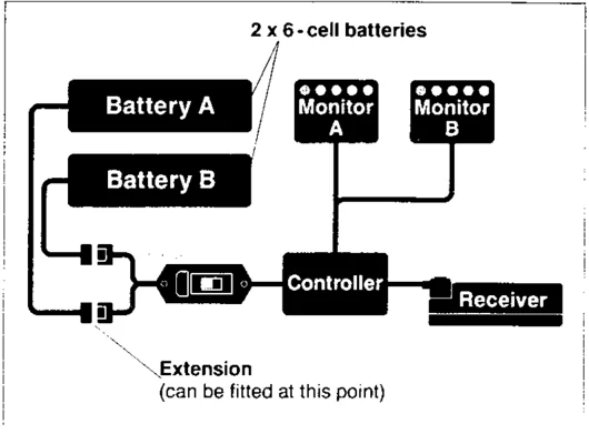
Fig. 64
Diagnosis (closed loop) operation For checking and making adjustments, the transmitter and receiving system can be linked by the Diagnosis Lead (Order No. 8 5105). The model must be fitted with a switch lead with integral charge/diagnosis socket (Order No. 8 5100). The RF module in the transmitter is switched out of circuit automatically, and can even be removed.
Closed-loop operation: ...saves power; as no RF signal is produced or radiated by the transmitter its current consumption drops to about 33% of the normal value; ...disturbs nobody, because the RF module is not functioning. ...cannot suffer interference, because RF signals are ignored by the receiver.
Important: You can only carry out closed-loop checking if none of the stick functions has been released as a Pupil function (see pages 74/74: Teacher/Pupil operations). When you pull out the plug from the transmitter, the RF module is switched into circuit again, which could interfere with your fellow modellers. So: be sure to switch the transmitter off before disconnecting the plug!
Care of the transmitter
Storage Protect your PROFI mc 3030 from: ● mechanical damage ● ambient temperatures above 60 degrees C (sunshine in a car) ● damp, solvents, model fuel, exhaust residue ● dust (in the workshop).
Please bear in mind that condensation may form on and in the transmitter if you move it from your warm workshop to a cold car or vice versa. Condensation may prevent the transmitter working properly. If you are not sure, carry out a careful range test, and let the transmitter warm up or cool down thoroughly. The transmitter should be completely dry inside.
The transmitter battery
Please note that new battery packs do not achieve their full capacity until after about 10 charge/discharge cycles. ● Charge new, rapid-charge batteries (or packs which have not been used for a long time) at least three times at the normal (slow) rate before rapid-charging them. ● Do not rapid-charge a battery unless you are certain that it was designed for it. ● Charge up batteries only when the ambient temperature is in the range 0 to 40 degrees C. ● Avoid placing mechanical stress on the power leads and on the cells themselves. ● Replace old batteries in good time. ● NC packs fall into the category of dangerous waste, and must be disposed of properly. Don't just chuck them in the rubbish bin!
Storing batteries
If you do not use your transmitter for a long period, take special note of the following points:
State of charge Experience shows that NC packs should be stored in a discharged (empty) state.
Self-discharge NC packs lose about 1% of their charge per day under unfavourable conditions, i.e. after three months' storage they are generally completely flat.
Maintenance charging The transmitter battery can be kept topped up, ready for use at any time, by charging it constantly at about 70 mA. The MULTIPLEX Combi-Charger Order No. 14 5540 includes a 70 mA output.
Types of servo
The right servo for every application Servos are the muscles of your radio control system. They move the control surfaces and steering linkages, operate throttle arms and brakes, switches and release mechanisms. For most purposes a high-quality "all-round" servo is quite good enough. These servos usually offer the best price : performance ratio.
Principal differences in servos:
Type of output Most servos are of the "rotary-output" type. The output arm rotates, usually through an angle of +/- 45 degrees. For special purposes – e.g. for retractable undercarriages – there are high-power servos which move through +/- 90 degrees. In some types of installation a linear-output servo offers distinct advantages. The fundamental disadvantage is that it is not possible to alter servo travel by fitting a longer or shorter output lever, as is the case with rotary servos.
Power (torque) Servo power is determined by the power of the motor and the reduction ratio of the gearbox. Greater power requires a more powerful motor (which consumes more current) or a higher gear reduction ratio (which slows down its response). If speed is unimportant – e.g. for a retractable undercarriage – the slow Power Servo is the best solution. In large, heavy models our Profi Servos come into their own. They offer outstanding power combined with high speed. If several Profi servos are used in a model, you should always select a receiver battery with a larger than normal capacity.
Speed Servo speed, as in a car, is a function of gearbox ratios. A low reduction ratio gives high speed, at the expense of power. For most applications our standard servos are quite fast enough. Only extremely high-speed models require specialised Speed Servos.
Resolution (accuracy) This is where the precision of a servo manifests itself. Our top models achieve a resolution figure of 0.2%.
Dimensions and weight For some purposes – especially for wing installation – by far the most important requirement is minimum size, combined with plenty of power. For such cases we recommend our Pico Servo.
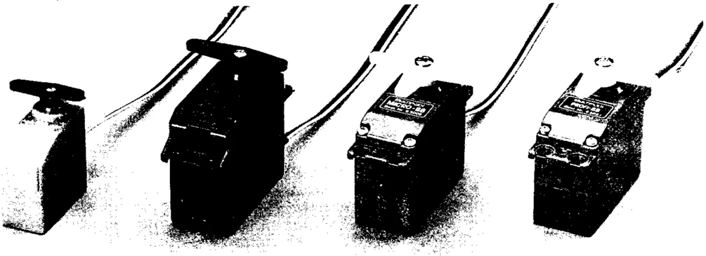
A variety of servo types Fig. 67 39
Cleaning the transmitter
If you need to clean your transmitter, take great care that no fluid gets inside the case. Use a mild household cleaner to clean the case. On no account use an abrasive or solvent-based cleaner. The best way of removing dust is to use a soft paintbrush.
Maintenance
Your PROFI mc 3030 transmitter contains no parts which require user maintenance. However, we do recommend that you carry out a range check and a check of all functions.
90
III. Some basic model technology
Specialist terms referring to fixed-wing aircraft
Spoilers: A vague term used for any part of the control system which primarily produces drag (and sometimes affects wing lift). For example: airbrakes, rotating trailing edge brakes or camber-changing flaps which can be deflected more than 30 degrees negative or positive.
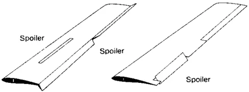
Fig. 65
Camber-changing flaps (or simply flaps) Control surfaces at the trailing edge of the wing, used to vary the camber of the wing section, and thus also the characteristics of the wing, to suit particular flight requirements. Positive deflections (flaps down) produce an increase in the wing's lift coefficient (slow flight), with a slight increase in drag. Small negative deflections, around 2 - 3 degrees, reduce drag for high-speed flight. If flaps are deflected more than about +30 degrees, drag rises considerably. Flaps make a useful landing aid (spoilers, crow system).
Flaperons: Full-span control surfaces at the wing trailing edge, which double as ailerons and camber-changing flaps.
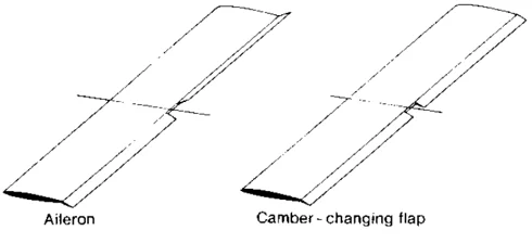
Fig. 66
Delta ("elevons"): Full-length control surfaces at the wing trailing edge, on models without a tailplane (delta, flying wing). The elevons double as ailerons and elevators.
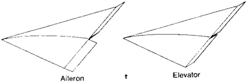
Fig. 67
Quadro: Full-length control surfaces (flaperons) divided into two separate flaps per wing. Each control surface doubles as aileron and camber-changing flap.
Dividing the flaperon into two makes it possible to set up the functions of aileron and camber-changing flap more efficiently in aerodynamic terms, particularly on long-span wings (better lift distribution and improved aileron response). In the interests of good aileron response, the aileron movement of the outboard control surface should be greater than that of the inboard surface; on the other hand, the flap movement of the inboard control surface should be greater than that of the outboard surface, to ensure docile stall behaviour.
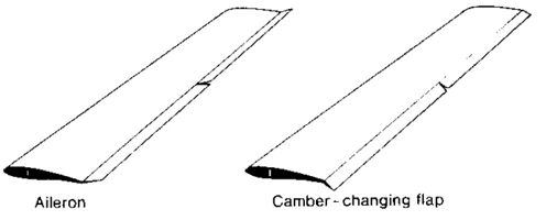
Fig. 68
Crow system (aileron brakes) An extension of the "Quadro" mixed function, utilising the mixed control surfaces as "spoilers". The inboard control surfaces are set to a positive braking position (flap down), the outboard surfaces to a negative braking position (flap up). Used on high-performance gliders (F3B class) which are not fitted with proper air-brakes or spoilers.
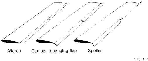
Fig. 69
Snap-flaps: Mixed function: elevator — camber-changing flaps. Often used on aerobatic models to reinforce the effect of the elevator. If up-elevator is applied, the camber-changing flaps are deflected down; the result is an increase in the wing's lift coefficient. Down-elevator is accompanied by up-flap, and the wing's lift coefficient is reduced. The overall effect is that the aircraft is capable of very tight looping manoeuvres – ideal for the "square" figures.
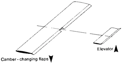
Fig. 70
V-tail (or "butterfly tail") Combined elevator and rudder in the form of a "V". When elevator is applied, both control surfaces move in the same direction. When rudder is applied, they move in opposite directions.
91
Differential: Term used for unequal aileron movements, intended to compensate for the "negative" roll effect, otherwise known as adverse yaw. If ailerons move an equal amount up and down, the aileron on the outside of the turn produces a yawing moment in the opposite direction to that of the turn, due to the increase in drag; an increased rudder movement is then required to counter the yaw. This makes for difficult control characteristics and a loss of efficiency, which can be very noticeable in large span model gliders.
Unequal aileron movements (much more up movement than down) can reduce this effect greatly, or even eliminate it altogether. The effect of adverse yaw varies from model to model, depending on the aircraft's geometry and wing sections. For this reason it is always necessary to carry out practical tests. As a good starting point we recommend 100% up-movement, and 50%-70% down-movement.
Some helicopter terms
Swashplate: This component mixes and transfers all control movements from the fixed control mechanisms to the rotating rotor blades.
Collective pitch variation: Generally known as collective pitch, or simply "collective". Variation in the pitch angle of all rotor blades at the same time, to control lift. If no change is made to cyclic pitch, the resultant lift force is coincident with the rotor shaft.
Cyclic pitch variation: Generally known as "cyclic pitch", or simply "cyclic". A variation in rotor blade pitch which alters over the course of one rotation. The effective result is that the plane of the rotor blades is tilted, and the resultant lift force is no longer coincident with the rotor shaft. It is used for: pitch-axis control: The resultant lift force of the rotor is tilted forward or back (when viewed from behind the model, looking forward). Corresponds to up- and down-elevator on a fixed-wing aircraft. roll-axis control: The resultant lift force of the rotor is tilted to right or left. Corresponds to aileron movement on a fixed-wing aircraft.
Tail rotor: Produces a force which counteracts the torque of the main rotor in single-rotor helicopters. Used for yaw control, corresponding to rudder control in a fixed-wing aircraft.
Gyro: The gyro registers unwanted yaw-movements, and sends appropriate corrective signals to the tail rotor control system. As every control command involving the main rotor results in a change in main rotor torque, the gyro is an important aid to the pilot.
Gyro suppression: This system reduces or entirely suppresses the effect of the gyro, so that the pilot can effect fast, intentional movements around the yaw axis.
Pitch/throttle curve: In an ideal helicopter the rotor speed would remain constant at all motor power settings; this is achieved by opening and closing the throttle whenever collective pitch is increased or decreased. The relationship between collective pitch and throttle can be considered in the form of a graph, or "curve"; the throttle signal is derived from the collective pitch signal.
"3-point curve": Corner points for minimum collective, hover collective and maximum collective pitch.
"5-point curve": As above, but with two additional points between the corner points mentioned above. The 5-point curve allows the rotor power requirements to be matched more accurately to the motor's power output characteristics.
Throttle pre-select (Idle-Up): Throttle setting for rotor idle speed under "no-load" conditions.
"Schlueter" control system: A separate servo is used for each of the three functions collective pitch, pitch-axis and roll-axis. Characteristic feature: the swashplate cannot move axially; collective pitch is controlled by means of a pushrod located inside the hollow rotor shaft.
 Fig 71
"Heim" control system: The functions collective pitch and roll are mixed electronically and passed to two servos. These servos control the swashplate in the "right/left" and "up/down" directions. The pitch-axis function is mechanically de-coupled from collective pitch. A separate pitch-axis servo controls the pitch-axis movement of the swashplate. Special feature: mechanical flare compensation is possible.
 Fig 72
92
"CPM" control system (HEAD MIX):
Abbreviation for Collective Pitch Mixing. The control signals for collective pitch, pitch-axis and roll-axis are electronically "composed" and sent to the servos. Between servos and swashplate there are no mixer levers or similar mechanics, so mechanical complexity is minimised.
Virtual swashplate rotation:
If a 3- (or more-) bladed rotor is mounted on a swashplate intended for a 2-bladed system, then the tilt of the swashplate no longer corresponds to the inclination of the rotor disc, as it is not possible in design terms to locate the mechanical linkage to each blade of a multi-blade rotor at a point 90 degrees in advance of its highest point. If the swashplate control system cannot be rotated through the appropriate angle to match the blade system, the pitch-axis and roll-axis servo signals can be mixed electronically to achieve an apparent (virtual) rotation of the swashplate.
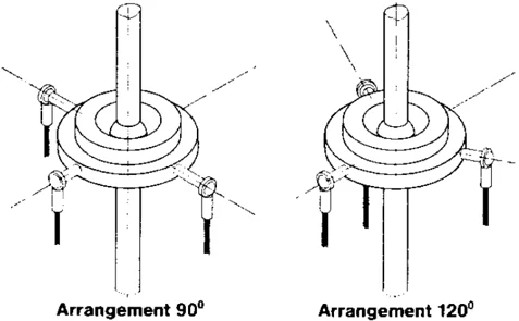
Arrangement 90°
Arrangement 120°
Fig. 73
93
Frequency bands, channels, crystals and spot frequencies
Four frequency bands are available for the control of models in the U.K.:
27 MHz band
35 MHz band
40 MHz band
459 MHz band
The latter band is used very little at present; the PROF! mc 3030 transmitter and receiver are only available on the first three bands.
The easiest way of imagining frequency bands is to compare them with the wavebands on your radio. Think of long wave (LW), medium wave (MW), and so on.
On your radio you can probably change bands by pressing a knob. With radio contro! equipment we can't do that: the transmitter has an RF module which has to be changed. The receiver, on the other hand, must be swapped for a new one.
The crystals in the transmitter and receiver determine the frequency and the channel. They must therefore be matched to each other with extreme precision. That is why:
Always use genuine MULTIPLEX crystals in your MULTIPLEX radio control equipment!
The channel number is always printed on one face of the crystal. next to it you will see either an "S" (Sender = transmitter) or an "E" (Empfaenger = receiver). Transmitter crystals are enclosed in a transparent blue casing, and "normai" receiver crystals in a transparent yellow one.
Caution:
A channel, or spot frequency, is a narrow section of one frequency band. Going back to our radio analogy, a spot frequency corresponds to one radio transmitter, or station. Instead of the frequencies themselves, which are difficult to remember, we use standardised channel! numbers.
Ordinary receiver crystals cannot be used with double-superhet receivers. Double-superhets require special types (DS crystals). They are fitted with an integral colourless plastic holder (Fig. 66).
Bands, channels and frequencies at a glance:
Crystals for the 27 MHz band
| _ é E . | transmitter frequency | narrow-band transmitter crystal. Order No. 165420 channel MHz | narrow-band receiver crystal, 5422channel MHz | a ss 2 fa 16 © = 3 >Se s > © EO Ee g a3Ze Passes xsess OtOUZAZZOG ° |
|---|---|---|---|---|
| 4 | 26995 13.4975 | 26540 | eeeeeee | |
| 5 | 27005 135025 | 26550 | © e ee | |
| 6 | 27015 | 13.5075 | 26560 | © e ee |
| 7 | 27025 | 13.5125 | 26570 | @ eo ee |
| 8 | = 27035 | 13.5175 | 26.580 | e e ee |
| 9 | 27045 | 135225 | ~~ 26590 | eeeeseeeece |
| 10 | 27055 | 135275 | 26600 | @ oe ee |
| 11 | 27065 | 13.5325 | 26610 | © eo ee |
| 12 | 27075 | 13.5375 | 26620 | eee |
| 13 | 27085 | 13.5425 | 26630 | © e ee |
| 14 | 27095 | 13.5475 | 26640 | @eeeeeee 0 |
| 15 | 27205 =—-13.5525 | 26650 | © © e@ | |
| 16 | 27415 27125 = | 18.5575 | 26660 | © © ee |
| 17 | 27135 | 13.5625 | 26670 | © eo ee |
| 18 | 13.5675 | 26680 | © eo ec! | |
| 19 | 27145 | 26690 | eeeeeeseoe | |
| 30 | 27.195 | 13.5725 | eeeeeeee © | |
| 24 | 13.5975 | 26.740 | eoeveeeevece | |
| 27.255 | 13.6275 | 26800 |
Crystals for the 35 MHz band
| - = 5 ° | transmitter Order No. 165430 frequency MHz | Order No. 16 5432 MHz | x a os = mcou-uZZno0 |
|---|---|---|---|
| 6t 35010 | 17.505 | 34555 | 0 @ 0 ee |
| 62 35020 | 17510 | 34565 | @@@ ee |
| 63 35030 | = 17515 | 34575 | eee eee |
| 64 35040 | 17520 | 34585 | eee eo e |
| 65 35050 | 17525 | 34595 | eee eo e |
| 66 35060. | 17530 | 34605 | eee eo e |
| 67 35.070 | 17535 | 34.615 | eee ee e@: |
| 68 35080 | 17540 | 34625 | e086 ee |
| 69 35090 | 17545 | 34635 | @ 0 @ ee |
| 70 35100 | 17.550 | 34645 | @@@ ee |
| 71 35.110 | 17555 | 34655 | @@@ ee |
| 72 35120 | 17.560 | 34665 | eee ee |
| 73 | 35130 | = 17.565 | 34675 | eee ee |
| 74 35140 | = 17570 | 34685 | eee ee |
| | 75 35.150 | 17575 | 34695 | @@@ ee |
| | 76 | 36.160 | 17.580 | 34.705 | @@@ ee |
| 77 35170 | 17.585 | 34715 | @00 ee |
| 78 35.180 | 17.590 | 34725 | e080 ee |
| 79 35.190 | 17.595 | 34.735 | @@@ oe |
| 80 35.200 | _17.600 | 34.745 | 0 @@ |
| | | oe |
Crtystals for the 40 MHz band
| channet | . wansmitter requ quency | narrow-band transmitter crystal Order No. 16 440/ch | narrow-band receiver crystal Order No. 16 5442/ch, |
|---|---|---|---|
| 50 | 40.665 | 20.3325 | 40.210 |
| 51 | 40.675 | 20.3375 | 40.220 |
| 52 | 40.685 | 20.3425 | 40.230 |
| 53 | 40.695 | 20.3475 | 40.240 |
| 54 | 40.715 | 20.3575 | 40.260 |
| 55 | 40.725 | 20.3625 | 40.270 |
| 56 | 40.735 | 20.3675 | 40.280 |
| 57 | 40.765 | 20.3825 | 40.310 |
| 58 | 40.775 | 20.3875 | 40.320 |
| 59 | 40.785 | 20.3925 | 40.330 |
| 81 | 40.815 | 20.4075 | 40.360 |
| channel | transmitter frequency | narrow-band transmitter crystai Order No. 16 5440/ch. | narrow-band receiver crysta’ Order No. 16 5442 27 |
|---|---|---|---|
| 82 83 | 40.825 | 20.4125 | 40.370 40.380 |
| 40.835 | 20.4175 | ||
| 84 | 40.865 | 20.4325 | 40.410 |
| 85 | 40.875 | 20.4375 | 40.420 |
| 86 | 40.885 | 20.4425 | 40.430 |
| 87 | 40.915 | 20.4575 | 40.460 |
| 88 | 40.925 | 20.4625 | 40.470 |
| 89 | 40.935 | 20.4675 | 40.480 |
| 40.965 | 20.4825 | 40.510 | |
| 90 | |||
| 91 | 40.975 | 20.4875 | 40.520 |
| 92 | 40.985 | 20.4925 | 40.530 |