Joking aside: everybody knows what the terms mean. But we think it is worthwhile cultivating a clear and correct style of thinking when dealing with this equipment. Everything that the transmitter "needs to know" about a particular model is included in a list, and the list is contained in a memory. When a memory is copied, it is the contents of the memory which are duplicated in a different memory, and so on.
Are we splitting hairs? We have to admit that we occasionally use the terms "list", "memory" and "model" interchangeably. In this manual we sometimes use the one term, sometimes the other, depending on what is most appropriate. However, if the "sloppy" terms occasionally sound less than precise, then you at least know why, and can always keep the idea of the list in the back of your mind.
One important point to remember: The model which is shown in the display, and which you are actually flying, is the "current" model. If you make any changes (e.g. to the trims, to servo travel, to mixing ratios etc.), then the modification is always recorded in the list (the "current" list) automatically, immediately. When you switch off, the memory is therefore always "up to date".
When you switch on again, this "latest state" is automatically restored, i.e. you never need to store anything expressly. We have found that this is the easiest and most natural method of working, and the one which strains the old grey cells the least.
But take care – there could be a catch! Let us imagine that you have test-flown a new model and trimmed it out with great care. You would not want to risk making any further changes to this "ideal list". Nevertheless, you would like to try something out as an experiment – but this would change your hard-won list. Or perhaps you have built a new, similar model, and want to use the same list, with minor modifications.
What to do? Well, the solution to the problem is simple: copy the list into a different memory, then "shift" to the new memory, and experiment to your heart's content.
This also applies to the "ready-made" sample lists. While you are unfamiliar with the transmitter, you should always work on copies of the original lists, and not on the "genuine originals".
For this reason "copying memories" is one of the most important things to learn at the start. It's simpler than you might think!
The "Files" Menu
All the tasks connected with memories are carried out from the "Files" menu. From the Status display you reach this menu with the key sequence M [icon]. You will see a display similar to this:
09 FIESTA PPM9 ---- FILES ---- COPY NAME SHIFT CHKTRIM
From here you select the following points with the arrow keys:
Copying: The term "copying" embraces the actual copying of one memory to another, but also related tasks, such as transferring a list from one transmitter to another.
Naming: This allows you to enter or modify the model's name in the list.
Shifting: This is where you go to switch to a different model whose list you have already stored.
Trim: From this sub-menu you can check whether the position of the trim sliders has been moved since "last time". More accurately: since the last time you used this memory.
After you shift memories this menu is called up automatically, as it is very likely that the trims have been moved since the last time you used the "new" memory. Naturally, you can also call up this menu without switching memories. In normal use, when you switch on the transmitter there is no automatic check that the the trim sliders are still at the position where they were when you last switched off, so this is a useful feature. For example, if you think that they might have been moved, but you are not quite sure.
These four sub-menus are explained in greater detail below.
The "Copying" Menu
From the Status Display you reach the "Files" Menu with the key sequence M [icon], and move from there to the "Copy" Menu with the [icon] key. You will then see this:
-- FILE COPY --- MODE:FULLY FR. 09:FIESTA TO 09:FIESTA
In the second line you see "Mode:" At this point there are possible variations from the simple copying procedure. We will discuss these later. At the moment we will only discuss the "normal" copying process, which is used most frequently.
47
How to copy a model list
Here we assume that you are already at the "Copy" Menu, as described above, and that the display is as shown on the previous page. The second line (Mode: FULLY) does not interest us at this point. The third line shows the "source"; namely the number and name of the model list which you want to copy. The transmitter suggests, in the lack of better knowledge, the "current" model. If that is what you want to copy, then line 3 is finished with too, and you can turn to line 4. However, we will assume that you want to copy a different model; e.g. the model "BIG LIFT" in memory No. 10. Press the key; the memory number begins to flash. You can now "leaf through" the memories using the or keys, or the Digi-Adjustor, until BIG LIFT appears. This defines the "source". The display looks like this:
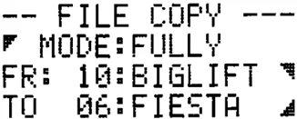
Now you have to enter the "destination" in line 4, i.e. the memory into which you want to copy BIG LIFT. Here again, the transmitter does not know what you are up to, and simply suggests the current memory (No. 6). Naturally this would overwrite the current list (FIESTA), which would be lost for good. If you no longer need FIESTA (you may have crashed or sold it), then you probably want that to happen. In that case, press the M key and you are done. FIESTA has been replaced by a copy of BIG LIFT in memory No. 6. However, we will assume that you want to copy BIG LIFT into another memory, which is not presently in use; e.g. into memory No. 5. Press the key; the number of the destination memory will flash. Leaf through again, using the or keys, until No. 5 appears. As every memory shows what is in it, you can still check whether the memory is actually empty, and that you are not unintentionally overwriting a model which you are still using.
The display should look like this:
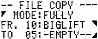
If this is what you want, press the M key, and you are finished. BIG LIFT is now stored in memory No. 5. By pressing the M key once more you leave the menu as usual. Here is the whole procedure again in brief: Select the source (the model which you want to copy) in line 3. Select the destination (the memory in which the copy is to be stored) in line 4. Press the M key; the transmitter makes the copy. Leave the menu with the M key. Note: As you have seen in the example, you do not need to "delete" the "destination" memory before you copy. Two more tips Tip No. 1 On occasion you may have second thoughts, and decide not to copy anything, in spite of being at the "Copy" Menu (for example, you may find that there is no vacant memory). You cannot just leave the menu without doing anything, since pressing the M key to leave the menu would execute the copying procedure. What to do? There are two ways out of this problem. The first: select as "destination" the same memory No. as the "source", and then press the M key. You have then copied the model on top of itself, which means that nothing has changed. Or the second: just switch off the transmitter. Tip No. 2 Let us assume that you notice too late that you have copied a list into the wrong memory, and have thus overwritten the list stored there. Now you've done it! But it's not a disaster. Please see page 49 for the final rescue solution (Memory "Mx").
How to delete a memory
If you are creating a "new" list, the simplest and least confusing route is usually to pick a memory which is vacant, or empty. This is not absolutely essential, as everything which you enter when assigning and adjusting overwrites the old contents of the memory in any case. However, bear in mind that some aspect of the previous model might lurk unseen in the new list, and it could give you a nasty surprise at an inopportune moment. For this reason the transmitter offers the option of erasing the contents of a memory. This is done from the "Copy" memory. Here is where the line "Mode: " comes into play – the line we skipped earlier on. We shall assume that you are still at the "Copy" menu. Press the key, and "FULLY" on the right starts to flash. Now press the + key, and "CONTROLS" (transmitter controls) appears. Press the + key again, and it turns into "ERASE". This is the mode which we now need:
Now all you have to do is enter the memory which is to be erased.
To do this, press the [icon] key. In line 4 the (destination) memory number starts flashing. Leaf through again with the + or - keys, or the Digi-Adjustor, until you reach the memory No. you want, and press the [icon] key. The memory is erased, and you can leave the menu in the usual way, with the [icon] key.
Note: The erasure process actually copies "EMPTY" into the destination memory. That is why you cannot enter anything in line 3 as the "source". "EMPTY" is a form of "source" in this case.
The "TRANSMITTER CONTROL" copying mode
Earlier on in this Copying section we used the "FULLY" copy mode. This simply copies the entire "list", i.e. all assignments and settings of transmitter controls and servos, into the new memory. As you have already seen when you leafed through to the "ERASE" mode, there is also the (transmitter) "CONTROL" mode. This is easily explained: If you select the "CONTROL" copy mode, only the assignments and adjustments of the transmitter controls are copied into the new memory. The "servo side" is not copied. The reason for this mode: Many pilots have a "standard" assignment and arrangement of the transmitter controls, which they use for every model. If you acquire a new model, in which only the servo arrangement is different, you can use this copying mode instead of the normal assigning and adjustment procedure for the transmitter controls. For the more complex models (e.g. helicopters, or models with many control surfaces), this can save time. It is never absolutely essential to use this mode; you could just as easily spend a little more time and assign and adjust your transmitter controls step by step, as described earlier in this manual. It is not necessary to describe how to copy the "CONTROLS". Apart from the fact that you select "CONTROLS" first, the procedure is exactly the same as when copying "ALL".
The "EXPORT" and "IMPORT" copy mode
These two "exotic" modes of copying are used to transfer entire "lists" from one transmitter to another. More details of this on page 79.
Note: You may be surprised to see terms such as IMPORT and EXPORT, which appear to have nothing to do with modelling. The reason is simple: your transmitter's programmer was forced to pick words which describe the feature as accurately as possible, which at the same time would fit within the maximum available number of letters!
The "Mx" memory - the point of no return
When "leafing through" the memories you may well have come across the fact that there are not really 15/99 memories: there are 16/100. Between memories No. 15 and 1 there is another memory, designated "Mx". However, you cannot use this memory to store a model permanently, like the other memories. It is "administered" by the transmitter itself, in the following way: 1) When you erase a memory, the transmitter automatically stores a copy of the deleted memory in Mx. 2) When you copy a memory, the transmitter automatically stores a copy of the previous contents of the "destination" memory. 3) The transmitter automatically stores a copy of the current memory as soon as you start modifying anything in it, e.g. assignments or adjustments. It does this before the modification in the current memory takes effect, and only at the first modification. And the point of all this? Well, the first case is quite obvious. If you make a mistake and erase the wrong memory, you have a "second chance": copy it back from "Mx" into the deleted memory, and all is well. The second case is also clear: if you copy into the wrong memory by mistake, and overwrite its previous contents, you can still save the situation, because a copy of the overwritten list is now in "Mx". Simply copy it back from "Mx" into the correct memory, and once again your bacon is saved. In the third case the reasoning is not quite so obvious, but the reason is similar. When modifying a list there is always the danger that you will make a fatal error. Perhaps the modification does not produce the desired effect. You know by now (see page 47) that every change is executed immediately in the current memory. Unless you made a back-up copy beforehand, and are working on the copy, the original list would be lost for ever. The automatic creation of a "back-up copy" reduces this risk. In an emergency you can recreate the "old state" again, by copying the contents of "Mx" back into the current memory, as described above. There is another use: Suppose that you want to "swap models", i.e. move two lists into each others' location. To do this you need an intermediate storage location. You could, in fact, use any free memory.
49
However, if there is no vacant memory available, you can't do that. And in any case it is easier to use "Mx" as the intermediate store. As an example, we will assume that you want to interchange the contents of memories No. 14 and 16.
First copy No. 14 to No. 16. The transmitter automatically copies the previous contents of No. 16 to "Mx". Now all you need to do is copy the contents of "Mx" back to No. 14, and you are finished.
The "SHIFT" Menu
How to switch models
To switch the transmitter over to another model – it must already be stored in a memory, of course – you just need to "call it up". You don't need to worry about the "current" model (the model in use before you change memories); i.e. you do not have to "save" it first. As changing models is a Memory operation, move to the "FILES" Menu from the Status Display, with the key sequence M ▣. You will see something like this:
01 BIGLIFT PPM9 ---- FILES ---- COPY NAME SHIFT CHKTRIM
You will see at once that you have to press the ▣ key, next to the word "SHIFT". You will see a new display:
01 BIGLIFT PPM9 CHANGE TO FILE NO. 01:BIGLIFT
The bottom line still shows the "current" model. You want to change this: so press the ▣ key; the memory No. begins to flash. "Leaf through" the memories using the + or - keys, or the Digi-Adjustor. As the numbers change, naturally the actual name of the model changes too, so that you quickly realise where you are. Once you have found the memory you want – in our example "02 FLAMINGO", press the M key, and you are finished – well, almost!
There is just one little problem:
you need to set the trim sliders back to where they were last time you flew the new model. The transmitter cannot do it by itself; it has plenty of brain power, but no muscle power. To cater for this, the "TRIM POSITION" menu appears automatically when you press the M key.
02 FLAMINGO PPM7 TRIM POSITION STICK : A B C D BEFORE: → ↓ ← ↓
Note: in the fairly unlikely eventuality that you have not shifted the trims at all since you last flew this model, you will see equals signs ("=") instead of arrows. Explanation in a moment! If you do not wish to adjust the trims, for whatever reason, press the M key to leave the menu. Press M twice more, and you are back to the Status display – all done! Normally, however, you will want to reset the trims to the earlier positions. As an example, we will do this for transmitter control A in the above display: Under "A" you see an arrow pointing to the right. Push the associated trim slider (transmitter control A = left stick, right/left) slowly to the right. At a particular point the arrow will turn into an "=" sign – that's all there is to it. If you push the trim slider further to the right, the "=" is replaced by an arrow pointing left. Now you can see what the arrows mean: they indicate the direction in which you must move the trim slider in order to reach the correct setting. Adjust the trim sliders for B, C and D in the same way. You are now finished, so press M three times to return to the Status display.
The "NAME" menu
How to enter or change a model name
The transmitter stores the various models in its memory under the numbers 1 to 15 or 1 to 99 (MASTER Edition only). For you as user it is much easier to be able to recognise each model by its name. Mind you, this assumes that you give your models sensible names; "Model No. 99" doesn't reveal much! For this reason you can differentiate each "model list" with a name. This name is then stored with the appropriate model (= memory) No., and displayed with the number.
There are certain restrictions to model names:
- Names may be no more than 8 characters long. "Characters" in this sense are letters, numbers and certain "special symbols", as in the following list: /0123456789;:=? ABCDEFGHIJKLMNOPQRSTUVWXYZ. Please note that there is an extra character between ? and A - a blank space, which is also considered a character. For example, "ASW 20" is 6 characters long. "ASW20" is only 5 characters long.
You don’t need to worry about sticking to the permissible characters, as the transmitter does not let you use any others. For instance, lower-case letters cannot be used and are not made available to you.
Very important: the eighth character should not normally be a number. There is a "special function" which requires a number as the eighth character, so do not use one otherwise. More details on page 80.
Here are a few possible names: ASW 20, TYPHOON, CORTINA, STUKA, NONAME; CORTINA3 or STUKA 01 are also possible, but read page 80 and heed the warnings first!
Tip: If you have a model list in a memory which you no longer need, and you want to mark it as such, it is best to erase it altogether. The erasure process gives it the name EMPTY automatically. You may think you will remember which memory is obsolete, but you won’t. It makes much more sense to erase memories which are no longer in use, than to continue to store "dead lists".
After this necessary preamble - let’s get down to it: From the Status display select the "Memory" menu, with the key sequence M [icon]. You will see a display similar to this:
Now select the sub-menu "NAME" with [icon]. This is what you will see:
Lines 3 and 4 automatically show the number and name of the "current" model. In our example this is No. 02 and "FLAMINGO".
If you want to change the name or pick another number, you must first select the memory No. To do this press the [icon] key; the displayed number starts to flash. You can now select the number you want, using the + and - keys (or the Digi-Adjustor). As you do this, the name displayed will also change, as it always relates to what is in the new memory.
We will imagine that you have selected Number 09 "CORTINA". The new name is to be "BAMBINO".
Press the [icon] key. The "C" of CORTINA starts flashing.
Using the + and - keys, or the Digi-Adjustor, you can now change the "C". In our example that is simple; press the - key once, and "C" turns into "B". Now it's the turn of "O". Press the [icon] key again, and the "O" flashes. Change the O to A, again using the + and - keys. Move to the next letter with the [icon] key, and so on.
The "underline" character, which you will see alternating with the flashing letter, is known as the cursor: the cursor marks the current position. Without the cursor you would not see anything at a blank space.
Enter the new name letter by letter. If you look carefully when you press the + and - keys, you will see that the various characters appear in the display in the sequence stated on the previous page. If you want to enter a space, select the "space symbol (between "?" and "A").
When entering a name you can only work from left to right, one character at a time. If you make a mistake, don't worry. You simply press the [icon] key until you reach the eighth character, after which the sequence begins again.
For those of you with absolutely no experience of computers, we will recap:
The old name is not "erased" immediately; instead each letter is overwritten in turn by the new name. Where there is to be "no new letter", you have to overwrite with a space.
Now we will assume that you have tackled this task successfully and the new name is on display.
Press the M key to leave the menu; then press it a second time, and you are back to where you started: the Status display.
The "TRIM" menu
How to check the position of the trim sliders
The transmitter "remembers" the position of the trim sliders by entering their values in the "current list". This gives you the chance to check, if you switch on and think that the trims might have been shifted accidentally since the last time you flew.
This is the procedure:
From the Status display press M and [icon] to go to the "Memory" menu. Now select "TRIM" with the [icon] key. You will see a display similar to this:
If your display were exactly like this one, you would correct the trims as follows: slide the trim slider A slowly to the right. At a particular point the right-facing arrow under "A" would be replaced by an equals (=) sign. If you were to push it further to the right, you would see a left-facing arrow.
The arrow after the colon (:) indicates the direction in which you have to move the trim slider in order to match the current position with the stored position.
In our example you would have to move the A trim to the right, the B trim forward, the C trim left and the D trim back, until an equals sign appears at each point.
You can now leave the menu with the M key.
Note: Every time you change models (shift memories) this menu appears, as you will have been flying a different model in the meantime, and it is very likely that you need to adjust the trims. And you will certainly want to carry on flying with the trims set to the same positions as the last time you flew the model.
Caution: Even if you are only entering the data for a model temporarily, be sure to set the trims. If you don't, the trim slider positions for that model will be lost next time you switch memories.
52
Mixers

In this Section you will get to know the mixers which the transmitter has to offer.
Before you dive in here, please make sure that you are familiar with the simpler setting-up tasks, such as assigning transmitter controls and servos, adjusting servo travel and direction and so on. Practise these procedures several times until you feel at home with them.
In our examples we will restrict ourselves to fixed-wing model aircraft; helicopters are covered in a separate Section (page 61). Nevertheless, all the basic information we provide here applies in full measure to the specialised helicopter mixers.
The mixers provided by the PROFI mc 3030 are operated in a rather different way from normal. We think that this new type of "operating philosophy" is much simpler than the conventional method.
For this reason we will first discuss our new method of considering mixers. You will see that the concept fits in elegantly with the simple and logical overall concept of the transmitter, with which you are by now familiar.
After this we describe the characteristics of the "pre-defined mixers" (explanation later); the description is brief, since everything always works in the same way.
Now, modellers are by nature inventive souls, and the probability is high that somebody will find he needs a mixing function which our programmer, in spite of his vast experience, has not thought of beforehand. For this reason there are the "User-defined mixers" ("USR-MIX") which you can "define" yourself. This gives you the chance to overcome the most exotic problems. These user-defined mixers are discussed in the final Section.
What is "mixing"?
Let's imagine a simple case:
Your model is fitted with camber-changing flaps or landing flaps. They are lowered for the landing approach, and thereby increase the lift coefficient of the wing. However, one result of this is usually an alteration in the pitch trim of the model – it becomes nose-heavy or tail-heavy. The pilot then has to apply "up" or "down" in order to keep the model on an even keel.
This manual form of "pitch trim compensation" can be automated by passing a proportion of the "flap signal" to the elevator. Of course, this has to be in the correct direction, and of a suitable magnitude. You don't need to worry that this part of the flap signal "goes missing"; the electronics are designed in such a way that the full signal reaches the flaps, even when part of it is "bled off" to the elevator.
The net result is that the elevator servo receives part of the "flap" signal in addition to its main "elevator" signal.
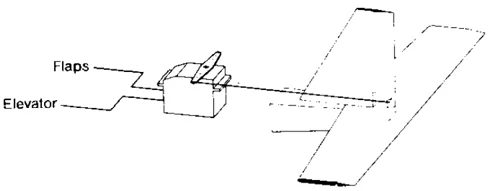
Fig. 29 Now we will refine the arrangement (and complicate it).
Your model is capable of flying smaller-diameter loops if the wing flaps deflect down slightly when you apply up-elevator. Once again the pilot could do it, but we will remove that task from him and automate the process by feeding a proportion of the elevator signal to the flap servo.
The net result is that the flap servo receives part of the "elevator" signal in addition to its main "flap" signal.
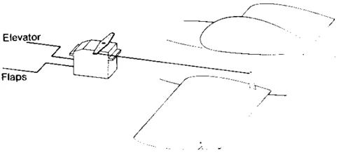
Fig. 30 A year or two ago we might have said this: "that's an elevator/flap mixer". Please forget that right now – it's just too vague to cover the possibilities. Our example is about to become even more sophisticated. The model has suddenly sprouted spoilers, allowing the pilot to make it lose height rapidly. In most cases spoilers also affect the model's pitch trim.
You can probably see what is coming: we feed a proportion of the spoiler signal to the elevator servo: again in the correct direction and of the correct magnitude, and the pitch trim compensation is automatically correct.
53
The elevator servo now receives the following signals: the main "elevator" signal part of the "flap" signal part of the "spoiler" signal
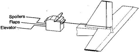
Fig. 31 Our earlier idea of a mixer is now creaking somewhat. And now the final touch: We don't always want to fly tight loops; for "normal" flying it is better if the flaps do not deflect automatically when the elevator is moved. Obvious solution: install a switch so that the part of the elevator signal that is fed to the flap servo can be switched on and off. We have introduced a switch into the signal line "elevator to flap input".
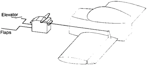
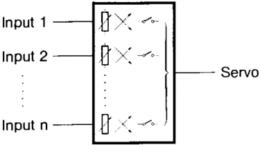
Fig. 32 Now you can probably see how it all hangs together: Each servo which is to receive more than one single signal is provided with an (imaginary) "black box". The "black box" has inputs for all the signals we need to pass to the servo. But it has only one output – and that provides the composite signal which is actually fed to the servo. Now we provide an adjustor for each input, so that each of the part-signals can be varied in size. A "reversing device" is also fitted for each signal. And finally, where it is likely to be useful, we fit a switch, so that each part-signal can be turned on and off. It is this imaginary "black box" that we call a mixer.
Now we will look at a different example: a V-tail. First we will only look at one tail panel – one "half". In this case we need a "black box" which combines the "elevator" and "rudder" signals. It is called a V-tail mixer. In slightly more technical and abstract terms: A V-tail mixer combines the "elevator" and "rudder" signals and feeds the composite signal to the servo. We need the same mixer for the other half of the V-tail. Of course, the size of the two signals is fully variable, as in the previous mixer. In this case we have to pay attention to the "prefix", i.e. the direction of rotation of the part-signals: the "elevator" part must work in the same direction for both halves of the tail. The "rudder" part must act in opposed directions. But this presents no problem, as we can, of course, adjust the direction of rotation separately for each part-signal. Even better: we do not need to worry any more about the mechanical linkages and the space available: when the model is complete, we apply, for example, "up elevator"; if the elevator moves down, we simply reverse the direction of rotation of the "elevator part-signal". The same applies to the rudder signals. Since the magnitude and direction of each part-signal is fully adjustable, you can see that installation problems are a thing of the past. As in this example, there are many other commonly used "mixed functions", for which "pre-defined" mixers can be used. A "flaperon" mixer, for example, produces a composite signal for the flaperon servos consisting of the basic flap and aileron functions (hence "flaper on"). If you have a model fitted with flaperons, you again need two such mixers: one for each flaperon servo. Commonly used mixers can be pre-defined. The part-signals for the functions of a pre-defined mixer are already laid down. Each mixer of this type is given a name which describes its use clearly. Such pre-defined mixers are available in an "adequate" number in your transmitter, and cater for all the most commonly used applications. You will find mixers for: V-tail, "V-tail +", flaperons, "elevator +", snap-flaps, delta, "aileron brakes (crow)", "Quadro". If at this point the operation of any one of these mixers is not clear from its title, don't worry. They are all explained in full at a later stage. You can implement each of these mixers (i.e. install the black box in front of a servo) as often as you like. The actual limit is nine times, since the system is "only" able to control 9 servos. That has to be the definitive answer to the oft-posed question "how many mixers?"! The answer is not what you might think, and certainly not 9 mixers. It is 9 mixer systems with 10 different transmitter controls to 4 different inputs, i.e. $10^4$ possibilities per servo!
54
How to use the pre-defined mixers
The use of the pre-defined, "ready-made" mixers is based on the same scheme that you have already come to know: first assign, then adjust. Once again the transmitter "offers" options in the form of menus. From what we have just said it should be clear that mixers are assigned to the servos.
First a simple example: the V-tail Here we will suppose that you have set up memory 03 for a model named "TEST", and assigned the controls like this: "Transmitter control B = ELEVATOR" and "Transmitter control C = RUDDER". Servos 2 and 3 are to operate the V-tail.
First the mixer is assigned to the servos: Move to the "Assign servos" menu. There you first select servo No. 2 in the usual way. Now "activate" the select function field in line 4 with the ☑key. Leaf through with the + key. The functions with which you are by now familiar from the normal assigning procedure appear one by one. After "AUX.5" and "MULTI-NAUT" come the mixers; please see page 32 for the full list. After "ELEVATOR +" comes "V-TAIL". This is the mixer we want. (After this comes the "V-TAIL+" mixer, which can do even more, but we will come to that in a moment). You will see this:
 03 TEST PPM9
- ASSIGN SERVO - SERVO 2 IS V.TAIL
Press the ☑ key, select servo No. 3 and repeat the whole thing for this servo. The assignment process is now complete.
You have now "informed" your transmitter that: Servo No. 2 operates V-TAIL, and Servo No. 3 operates V-TAIL.
It also knows that it is to place the appropriate mixer before each of the two servos. In more abstract terms: you have assigned servos 2 and 3 to the "V-Tail higher mixed function". Leave the menu in the usual way.
Now we come to setting up the mixer. Move to the "Servo adjustment" menu. Press the ☑key to select the sub-menu "TRAVEL + REVERSE". Select servo No. 2 in the usual way. You will see this:
 03 TEST PPM9
F SER.2: V.TAIL
PART :ELEVATOR
L+100% B+ ON
Line 3 should now make sense (it probably didn't before); here you see "Part: ELEVATOR". Press the ☑ key and adjust the throw to the one side (stick back) and then the other side (stick forward), just as if setting up in the normal way. There is no reason in this case why you should set unequal movements, so set both to, say, 40%.
If you have an actual model to hand while you carry out this practice procedure, check at this point that "up" on the stick makes the elevator rise. If this is not the case, press the R key, and it will be reversed.
Note: If you set mixing ratios which add up to less than 100%, then the mixer will operate in a "linear" fashion, and the control signals will never be restricted. You could, on the other hand, leave both inputs at, say, 100%. In such a case, if you apply elevator or rudder one at a time, you will have full travel available. However, as soon as the sum of the two inputs for either control surface exceeds 100%, i.e. when a lot of elevator and rudder are applied simultaneously, the movement will be restricted, as the servo and the control surface cannot move to more than 100% of maximum. The effect is aerodynamic asymmetry, which can be disturbing.
"Linear" mixing (no more than 100%) is the most elegant solution, but in practice a setting part-way between the two extremes has proved a very effective compromise.
Now to the rudder input. Press the ☑ key, then +. "Input: ELEVATOR" is now replaced by "Part: RUDDER". You will see this:
03 TEST PPM9 F SER.2: V.TAIL PART : RUDDER L+100% C+ ON
Press the ☑ key again, then set the "rudder" input for both directions of rotation; in our example 60% for each side. Here again, check that the control surfaces move in the correct direction (if you have a model handy). Reverse the function, if necessary, with the R key. We hope you didn't find that all too confusing. Never mind – you can repeat the whole operation now for servo No. 3!
One further note: In the right-hand bottom corner of the display you will always see "ON" or "OFF" or "S..". If you "activate" this corner with ☑, you can switch between "ON" and "OFF" with the R key. This switches the corresponding input on and off. This can be a useful feature at the setting-up stage.
And now a more complex example At the start of this Section we discussed a model which featured pitch trim compensation for camber-changing flaps and spoilers, and elevator to flap mixing.
We will assume that transmitter control B has been assigned to the "elevator" function, control D to the "spoiler" function and control F to the "flap" function. The following servo assignments have also been made: Servo No. 2: elevator Servo No. 4: spoilers Servo No. 6: camber-changing flaps
Here we come to another special feature which, although it has nothing to do with mixing, is important in an indirect sense.
We will assume that the "basic position" (spoilers closed) of control D is "forward"; to extend the spoilers the stick is pulled right back.
At the basic position a very large signal is already present – namely full travel forwards. Of this a certain proportion would reach the elevator, and that would need to be "compensated away" by some means.
The transmitter offers a better alternative, namely the "Normpos" (Normal Position) control option. If you have not yet tackled this feature, you should do it now; otherwise you will encounter problems in the next section. Please refer to page 43.
You must set this option to "forwards" (forward arrow in the display). Assuming, that is, that your spoilers are retracted with the stick forward!
This action compensates for the undesired basic mixing input before it reaches the mixer. It has no effect at all on the signal to the spoiler servo itself.
From now on take care that control C is set to one or other of its end-points for all your adjustments. Alternatively, you could switch the "SPOILER" input off when adjusting the elevator, as described above.
But enough of the preliminaries.
First step, as always: assigning: Move to the "Assign servos" menu with the key sequence M◀◀◀.
For servo No. 4 (spoilers) everything is clear; there is no mixing. So, just as with "normal" assignment, first select servo No. 4, then assign "SPOILER" to it. Now to the elevator.
Select servo No. 2, then press the ◼ key; the control function field in line 4 starts flashing. Once again the familiar "list of options" appears. After "AUX.5" and "MULTNAUT" comes "ELEVATOR+":
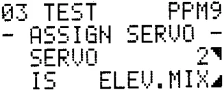
03 TEST PPM9
- ASSIGN SERVO - SERVO 2◀ IS ELEV.MIX◀
This is the mixer that we need. (It is described in detail in the preamble to the detail description of mixers which follows.)
That's all there is to it; flap servo next: Select servo No. 6, then select the servo function field with the ◼ key. Leaf through again with the ⊕ key. For an unmixed flap function you would now select "FLAP"; because of the mixer, however, you have to continue leafing through until "SNAPFLAP" appears: the name of the mixer which produces the desired mixing effect:
03 TEST PPM9
- ASSIGN SERVO - SERVO 6◀ IS SNAPFLAP◀
Now to the setting-up process. Move to the "Servo adjustment" menu. Servo No. 4 is the first one to adjust. There is not much to say about it: set the direction of rotation and the centre point (if necessary) in the usual way.
The flap servo (No. 6) comes next. In this case we should really call it the snap-flap servo, because we have assigned the SNAPFLAP function to it. Hair-splitting? Well, that's how your transmitter sees it. Select servo No. 6. You see this:
03 TEST PPM9 ◀SER.6:SNAPFLAP PART : FLAP◀ ◀+50% F↑ ON ▶
In the "Part" line you will see "FLAP" already. So we will set up this input first.
Release the input value field with the ◼ key (value flashes). Check whether the direction of servo rotation is correct. If not, press the Ⓡ key. But the values themselves? We cannot tell you exactly what they should be, as this depends on your model, and in particular on the length of the actuating arms on the servo and the control surfaces. It is best to measure the result on the flaps themselves; for camber-changing flaps a good starting point would be around 5 - 10 degrees up and 15 - 20 degrees down. Set the slider to the one end-point and then the other, and use the ⊕ and ⊖ keys to set the % values.
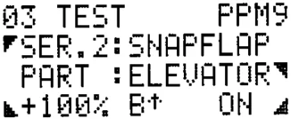
Now to the "elevator" input. Press the ◼ key, then the ⊕ key. With ELEVATOR flashing, the display will look like this:
03 TEST PPM9 ◀SER.2:SNAPFLAP PART :ELEVATOR◀ ◀+100% B↑ ON ▶
Activate the input value field with the ◼ key once more. Check the direction of servo rotation; for snap-flaps the elevator must move in opposition to the flaps, i.e. up-elevator with down-flap. Is that how it is? If not, reverse it with the Ⓡ key. Apply "full up" at the elevator stick, and set the desired flap deflection with the ⊕ or ⊖ keys. Repeat the process for "full down" elevator. A good starting point for both sides would be around 5 - 10 degrees flap deflection; you will be able to find the optimum settings later on, during test-flying.
Do you remember that we wanted to make the elevator · flap mixing switchable?
That comes next.
You can – or rather, must – tell the transmitter which switch is to carry out this task (you have to do this because your PROFI mc 3030 sets virtually no restrictions on what you can and cannot do).
We will assume that you decide on "S5". In this case, press the ◼ key. Tap the ⊕ key repeatedly until "S5↓" appears and flashes. The arrow shows that the switch must be pushed in that direction to switch it ON, i.e. the coupling is then effective. If you want to reverse this, press the Ⓡ key, and the job is done.
You are finished with the snap-flap servo. Now to the elevator (more accurately: ELEVATOR+) servo, in our case No. 2.
Select servo No. 2 with the ▣ and ☐ keys. The display will look like this:
Part: "ELEVATOR" is already there, so we will set that up first. Release the input value field with the ▣ key, then check the direction of rotation; reverse it if necessary.
Then set the travel itself on both sides: 90% would be a useful starting point.
The "SPOILER" and "FLAP" inputs are adjusted next, but we don't need to describe the adjustment procedure in detail again. In both cases it is all "business as usual": select the input, set the value for both sides. Reverse the function if necessary.
Our tip: Practise "adjusting inputs" until you are confident with the procedure. Later on, at the flying site, you will also need to know what to do, so that you can make sense of the test-flying process. It is not always quite as quiet and calm out there on the flying strip as it is in your workshop; and in such "mild stress situations" you can easily make an error - unless you are confident of what you are doing, that is. The same applies if you use the "ready-made lists" supplied with the transmitter, without assigning anything yourself. It is almost impossible to use any of the mixers unless you know how to set and adjust input values.
Never attempt to adjust anything from the keypad when you are flying a model. Instead use the Digi-Adjustor, which is always switched "in parallel" with the + and ☐ keys, when it makes sense to use it.
The basic rule is this: keep the keypad flap shut while you are flying!
One final thing you might like to try out in addition to the last example (this has nothing to do with mixers): Try out the transmitter control option "Fixed Value" for the flap function (see page 42). You will see that every aspect of the adjustments you have made regarding the slider control still functions if you "override" the slider position with a switch.
Description of the pre-defined, "ready-made" mixers
Now that you have become familiar with the way the mixers are assigned and adjusted, here is a list of the pre-defined mixers in the same sequence as they are offered by the transmitter when you "leaf through" the options.
With all mixers the stick unit trim sliders are automatically included where it makes most sense, or where it is standard practice. You don't need to concern yourself with them at all.
Examples: For a "V-tail" the elevator trim works in the usual way; for "snap-flaps" it does not. For each mixing input the size and the prefix (rotary sense of the servo) can be adjusted. The inputs can be switched on and off wherever that is of practical advantage. You can assign each mixer as often as your application demands it.
Example: You must use the "Quadro" mixer at least four times; less than that number means that it is no longer a "Quadro" mixer. However, there is no reason why you should not use it six times if your model has three wing control surfaces on each side. One more time – just to remind you: You can set any input to "zero" and then disregard it altogether. This may make a particular mixer suitable for a different, but similar purpose.
Example: With the "Quadro" mixer you could set the "elevator" input to zero, and you then have a mixer which involves "flaps" and "ailerons" only.
Mixers for fixed-wing models
The "ELEVATOR+" mixer
Inputs: Elevator Spoiler Flap
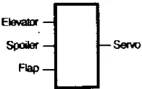
The mixer is usually assigned as follows: Elevator servo Main application: Standard models with camber-changing or landing flaps and/or spoilers.
The "V-TAIL" mixer
Inputs: Elevator Rudder
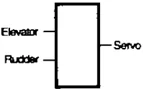
The mixer is usually assigned as follows: V-tail servos Main application: Model aircraft with V-tails
The "V-TAIL+" mixer
Inputs: Elevator Rudder Spoiler Flap
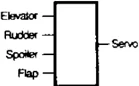
The mixer is usually assigned as follows: V-tail servos Main application: Models with V-tail and/or spoilers and/or camber-changing or landing flaps.
The "FLAPERON" mixer
Inputs: Aileron Flap
The mixer is usually assigned as follows: Flaperon servos Main application: Models with flaperons (combination flap/ailerons)
57
The "aileron brake" (Crow) mixer Inputs: Aileron Flap Spoiler Elevator
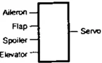
The mixer is usually assigned as follows: Flap and aileron servos. Usually 4 servos. Main application: Models in which the "Crow" configuration is to be used as an aid to flight path control in certain flight situations (descent, landing approach). Can also be used for pure "aileron brakes".
The "SNAPFLAP" mixer Inputs: Flap Elevator
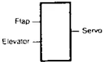
The mixer is usually assigned as follows: Flap servos Main application: F3A class aerobatic models for "square" manoeuvres
The "QUADRO" mixer Inputs: Aileron Flap Elevator
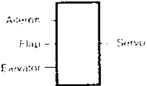
The mixer is usually assigned as follows: Flap and aileron servos Main application: Gliders with "Quadro" flap configuration (flaps support ailerons, ailerons support flaps)
The "DELTA" mixer Inputs: Aileron Elevator
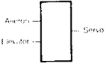
The mixer is usually assigned as follows: "Elevon" servos (combination ailerons/elevators) Main application: delta model aircraft and flying wings.
Mixers for model helicopters
The "TAIL ROTOR" mixer Inputs: Collective pitch Yaw-axis Fixed value
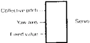
The mixer is usually assigned as follows: Tail rotor servo Main application: Model helicopters with main rotor torque compensation via tail rotor
The "HEIM HEAD" mixer Inputs: Collective pitch Roll-axis
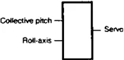
The mixer is usually assigned as follows: Swashplate actuation servos Main application: Model helicopters with Heim-type swashplate linkage, or similar
The "HEAD-MIX" mixer Inputs: Collective pitch Roll-axis Pitch-axis Geometry Phase
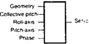
The mixer is usually assigned as follows: Swashplate control servos Main application: Model helicopters with "Collective Pitch Mixing" swashplate linkage
The "DYNAMIC-THROTTLE" mixer Inputs: Throttle Roll Pitch-axis Yaw-axis
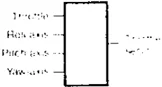
The mixer is usually assigned as follows: "Throttle" servo Main application: All model helicopters in which throttle is not controlled directly by the pilot, but is controlled indirectly according to the power absorption of the main and tail rotors. Special feature: The "roll", "pitch-axis", and "yaw" inputs are mixed "without prefixes", as the power requirement of the main and tail rotors rises from zero "on both sides".
The "FLARE" mixer Inputs: Pitch-axis Collective pitch
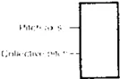
The mixer is usually assigned as follows: Pitch-axis servo Main application: Helicopters with separate pitch-axis servo (e.g. Schlueter, "Shuttle"), if "flare" mixing is desired.
The freely definable mixers ("USR-MIX" mixers)
In contrast to the "pre-defined" mixers discussed in the previous Section, the user-definable mixers give you the chance to select precisely the mixing inputs you require. This feature caters for all possible applications for which no pre-defined mixers are provided. Once they have been "defined", these mixers can be used exactly like the "pre-defined" mixers.
This means that they are assigned and adjusted in exactly the same way. And in exactly the same way, switches are provided for turning individual inputs on and off. These mixers give you total freedom!
Note: In practice, the term "defining mixers" means that you select: Input 1 controls (say) aileron Input 2 controls (say elevator
58
That is all you need to do to define a delta mixer. You can now assign the mixer in the standard way. However, when you try out the system, you will discover:
No trims!
Right then, back to defining the USR-MIX mixer, release the input field with the Ⓐ key, and add the trim.
E.G. Input 1 1. AIL +T
And the result? Nothing! Has the transmitter gone wrong?
No, there's nothing wrong: first you must re-assign the modified USR-mixer. Move to the servo assignment menu, select the appropriate servo, and activate the input field. The legend USR-MIX 1 flashes – now the altered USR mixer is active.
You may find this difficult or complex, but bear with us; this "trap" in fact offers immense possibilities.
If you are really clever, you will already have realised the potential:
Since we have to re-activate the mixer each time, we can alter the USR mixer definition between each servo assignment (servo 1, 2, 3 etc.), so that each of the 9 servos has its own USR mixer. But – of course – there has to be a drawback.
The USR mixers can indeed all be different, but they all have the same name, e.g. USR-MIX 1.
At this point we will come back to the game we played before, in answering your friends' question:
"My transmitter has 6 mixers; and yours?"
Independent of the 13 ready-made mixer systems, each of which you can apply 9 times, you now have the USR mixers. These can be assigned up to 10 different inputs for all four channels. That means: 104 possible mixers per servo!
And if you happen to possess the Master-Edition transmitter you can set up 891 of these mixers differently!
Sample applications:
As the first example, imagine an electric-powered model aircraft. Imagine also that it has the unpleasant habit of becoming more and more tail-heavy, the more the "throttle" is opened (the more power is fed to the motor). Quite why this occurs we don't need to waste time thinking about: perhaps the modeller just wanted an easy life, or maybe he made a mistake at the building board.
Now, wouldn't it be nice if we could mix down-elevator in with the "throttle" automatically, so that more "down" was applied as the throttle was opened. We would then need a "motor" and "elevator" mixer.
A case for a mixer – a USR-MIX mixer.
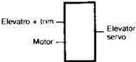
When "right rudder" is applied, the left motor is to be fed with more current, and the right one less; and the other way round when "left rudder" is applied. Here we need two mixers of the same type for the inputs "rudder" and "motor":
If the two motors have already been set for separate
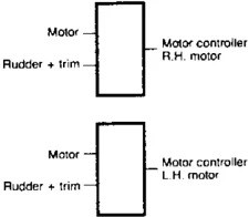
control from the transmitter, using the assignments "MOTOR" and "MOTOR-2", then the solution can be even more sophisticated, but we won't go into that here.
How to "define" the mixers
Every definable mixer has four inputs. To define the mixer, we need to tell the transmitter which control functions it is to send to these inputs.
That is what we mean by "defining".
Naturally, this is done by means of a menu, which you will find in the "bottom right-hand corner" of the "Assigning" menu.
Starting from the Status display, move to the "Assigning" menu with the key sequence Ⓜ⃞; then select "USR-MIX" with the ⬛ key. You will see this display:
- DEFINE MIXER - ▸USR-MIX1 IS CONTROLLED BY: ◀1. UNUSED ◢
Now we will define the mixer for the first example. This will be USR mixer 1.
Of the four possible inputs we need only 2: one for "MOTOR", the other for "ELEVATOR". In line 2 (Number and "name" of the mixer) you will see "USR-MIX1"; i.e. there is nothing to be done here.
Now we will "define" the inputs in turn: in line 4 you will see "1", which is the first input; we can leave it as it is.
Press the ⬛ key; and the "type of input" = control function can be entered. Leaf through with the ⊕ key until "MOTOR" appears. That's it done.
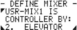
Now to the second input. Press the ⬛ key, followed by ⊕. "1" turns into "2". Press the ⬛ key again, then leaf through with the ⊕ key until "ELEVATOR" appears:
- DEFINE MIXER - ▸USR-MIX1 IS CONTROLLED BY: ◀2. ELEVATOR ◢
Now you really are finished. Inputs 3 and 4 are not used.
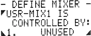
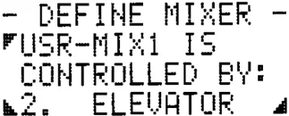
It is always possible that there could be something undesirable left here from an earlier mixer definition, so we ought to have a look, to be on the safe side: Select input 3 as discussed above. If you see "------" (Nothing) there, move on immediately to input No. 4; otherwise leaf through with the [+] key until "------" appears. Repeat the process with input 4.
This really does complete the task. Leave the menu in the usual way with the [M] key.
At this point a little "operating convenience" is built in: you are taken immediately to the "Assign servos" menu, where you can carry out this process. If you do not wish to do this, just press [M] again.
The result of your work, in diagrammatic form:
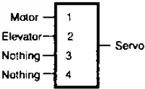
To assign this mixer to the elevator servo, leaf through until you see "Servo No. . controls USR-MIX1". number of servo
If you want to adjust this servo, you must then, as with the other mixers, adjust both inputs "MOTOR" and "ELEVATOR".
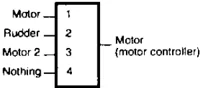
The second example in abbreviated form: For this you use USR mixer 2. Assign "MOTOR" to input 1; "RUDDER" to input 2.
If you assign "MOT-2" to the 3rd input, then a further refinement is automatically available. Why not try and work out what it is? (clue: bear in mind that you can later switch off or set inputs to zero).
Input 4 is again set to ------ (Nothing).
This mixer in diagrammatic form:
And now one small, but very important difference: What happens to the trims?
With many mixers it is necessary to include the trim slider positions with the "pure stick signal". For example, that applies to a V-tail, otherwise it would not be possible to trim the elevators and rudder. The same also applies to the elevator control of a flying wing model.
On the other hand there are mixers in which the position of the trim sliders should not be included. Example: "snap-flaps" on an aerobatic model. In this case the wing control surfaces should not deflect when the elevator trim slider is shifted; flap movement is only required when you "control" the elevator.
It depends therefore on your particular application, whether you want the mixing inputs with or without trims, and this applies equally to the USR mixers.
You can choose this too: We will return to the first example we discussed here. We had this display:
- DEFINE MIXER - USR-MIX1 IS CONTROLLER BY:
- ELEVATOR
Press the [key] key again; "ELEVATOR" flashes.
If you now press the [R] key, "+T" will appear next to it. This means "with trim", and indicates that the trim position is now mixed in with the ELEVATOR input:
- DEFINE MIXER - USR-MIX1 IS CONTROLLED BY:
- ELEVATOR+T
If you press the [R] key again, "+T" disappears again, and the mixing occurs "without trims".
One last time: Please bear in mind (as already described above) that you must re-assign the USR-Mixers every time you alter their definition, otherwise the changes will not take effect.
Helicopter control systems
Over the course of its existence the model helicopter has developed into a sophisticated and demanding machine. The demands these machines make on the radio control system are no less comprehensive. The PROFImc 3030, with its vast flexibility, is more than a match for all these requirements; thanks in particular to the specialised "helicopter mixers" and the user-defined mixers, which can be used to fulfil almost any conceivable need. Experts will also be delighted to exploit the possibility of "switching memories in flight" (see page 76). If you already have some experience with choppers the following Section will probably present no problem.
If you are a beginner to the world of the whirling rotor, we strongly advise you to read and study modelling magazines and specialist books to complement the information in this manual.
That is not because the PROFImc 3030 is complicated, but because helicopters are inherently complex. And because it is not possible to start with 2 or 3 functions, as with a fixed-wing model. It is far outside the scope of this manual to go into the basics and finer points of helicopter control systems, as they are by no means as easy to understand nor as easy to imagine as those of fixed-wing models. Some of the commonly used terms are explained in this section where necessary; and you will find some further explanations under "Some helicopter terms" on page 90.
In this Section we start from the assumption that you are already familiar with the way the transmitter works, so that we can concentrate on the characteristics of the helicopter.
Even if you consider yourself an expert and a helicopter specialist you should at least carry out a few "dry runs" with the fixed wing examples, so that you become familiar with the way the transmitter works.
As a minimum, you should feel at home with the method of finding your way around the menus, and with selecting, assigning and adjusting servos and transmitter controls.
Basically the "helicopter" transmitter is operated in the same way as for a fixed-wing model. Everything that we have said up to now on working with memories, mixers and so on, applies in full to the helicopter transmitter.
However, there is one fundamental difference: every modern model helicopter is flown with at least one mixer right from the start, and most of them feature several mixers. The "collective pitch/throttle curve" is another feature which is peculiar to the helicopter world.
But now: down to business.
The assignment process for helicopters
If we disregard the early, very simple helicopters, which managed without collective pitch, the model helicopter requires at least five primary control functions:
- Collective pitch
- Pitch-axis (fixed wing: elevator)
- Roll-axis (fixed wing: aileron)
- Yaw-axis (tail rotor - fixed wing: rudder)
- Throttle; usually linked to and derived from collective pitch
Commonly used auxiliary functions: 6. Gyro suppression and 7. Mixture adjustment for the motor.
Assigning the "transmitter control" end of the system
At the transmitter end the four main control functions: COLLECTIVE PITCH, PITCH-AXIS, ROLL and YAW have to be assigned to the two transmitter sticks in the usual way.
As the "THROTTLE" function is controlled in two ways – partly via a derived signal from "COLLECTIVE PITCH" and partly via a separate control (more details later) – a transmitter control must also be assigned to it; usually one of the two sliders.
The other slider is used for mixture adjustment. Start by moving to the "Assign transmitter controls" menu as described before. Assign the transmitter controls A - D to the control functions COLLECTIVE PITCH, ROLL, PITCH and YAW, using the arrangement you prefer.
Assign slider E or F to "THROTTLE"; then the remaining slider to "MIXTURE".
If you are using a gyro which can be controlled from the transmitter, a further transmitter control needs to be assigned to it; for example one of the "switched channels" H; in the transmitter's language: transmitter control H = GYRO.
If you do not need mixture adjustment, you could assign one of the sliders to the gyro.
Assigning at the "servo end"
Here things get a little more complex. But let's do things in the right order!
61
In the model there are three groups of control functions:
- The tail rotor (yaw) control system, including gyro suppression
- Throttle control system including mixture adjustment
- Swashplate (main rotor) control system.
No helicopter can manage without this:
The tail rotor control system
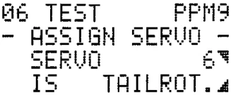
Move to the "Assign servos" menu. Select in the usual way the desired servo number, and activate the servo function field in line 4 with the key. "Leaf through" with the + key until "TAILROTOR" appears:
06 TEST PPM9
- ASSIGN SERVO - SERVO 6 IS TAILROT.
In our example servo No. 3 is now assigned to tail rotor control. This automatically makes available the essen-tial mixer which passes part of the collective pitch signal to the tail rotor servo. All you need to do later is set the level of the two inputs.
Important: Be sure to assign "TAIL ROTOR". If you assign "YAW" instead, you will have the normal stick function, but not the collective pitch mixing – i.e. no static tail rotor compensation!
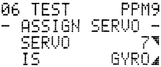
Set up gyro suppression in the same way: As the "sensitivity" input of the gyro is connected to the receiver in the same way as a servo, the "formal" designation here is: "Servo No. .. controls GYRO". In our example the gyro is connected to receiver output 6. So: press the key and select servo No. 6. Press and leaf through until "GYRO" appears:
06 TEST PPM9
- ASSIGN SERVO - SERVO 7 IS GYRO
Leave the menu as usual; that's it – done!
The throttle control system
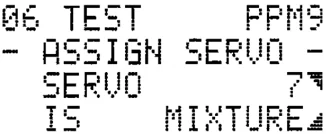
First the mixture adjustment At the "Assign servos" menu select, say, servo No. 7; then press the key and select "MIXTURE":
06 TEST PPM9
- ASSIGN SERVO - SERVO 7 IS MIXTURE
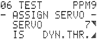
Now the "throttle" servo. First we select the appropriate servo again; in our case No. 4. Now, instead of the simple "THROTTLE" function as on a fixed-wing aircraft, we are offered the mixed function "DYN.-THROT." (dynamic throttle). This mixed function allows you to "switch in" part of the ROLL, PITCH and YAW control signals to the throttle signal. This is desirable because every control movement requires extra power from the motor. If you do not want to use this feature, the ROLL, PITCH and YAW inputs will be set to zero. So: press the key, then leaf through with the + key until you see "DYN.-THROT.":
06 TEST PPM9
- ASSIGN SERVO - SERVO 7 IS DYN.THR.
That's all there is to it here, too. Incidentally: if you don't hold with such refinements, you can always use the simple "THROTTLE" function. In that case the mixing arrangements simply do not apply.
The swashplate control system
Here we can't avoid getting a little deeper into the technology, as there are several different rotor head control systems, or designs, which differ widely from each other. In fact they all do the same job: they provide control of collective pitch, roll-axis and pitch-axis. However, the different systems make quite different demands on the number of servos and how they are used. For this reason we present here a brief description of the three most important systems, and the assignments required for each:
- The "classical" fixed swashplate This design is used, amongst others, on the "Schlueter System 80" and the "Shuttle". The swashplate cannot move along the axis of the rotor shaft; it can only tilt. Collective pitch control is via a pushrod which runs inside the hollow rotor shaft, or in a groove in the rotor shaft. Collective and cyclic pitch are mixed mechanically. "higher up", at the rotor. The swashplate is controlled by two servos, set at 90 degrees to each other.
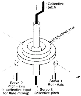
Fig. 33
62
There are therefore three servos for collective pitch, roll-axis and pitch-axis, which have entirely separate functions.
Servo No. 1 controls ROLL-axis Servo No. 2 controls PITCH-axis Servo No. 5 controls COLLECTIVE PITCH
If you wish, you can mix in the pitch-axis input to collective pitch at a later stage, if you find it necessary (for the transition from cruise to hover). To achieve this, assign "FLARE" to the pitch-axis servo. Please note that if you change the assignment, all the previous pitch-axis servo adjustments will be lost.
2. The "CPM" swashplate
CPM stands for "Collective Pitch Mixing". This type of linkage is to some extent the extreme opposite of the fixed swashplate. In this case the swashplate is free to move along the rotor shaft in the axial direction. Moving it axially produces collective pitch control; tilting it produces cyclic pitch control.
Three servos are again required, but in this case all three act on the swashplate. This arrangement is known as a 3-point linkage. However, it is possible to use more servos to control the swashplate.
A 4-point linkage presents no problem to the transmitter. You could even "distribute" 5 or more servos around the rotor head, should a helicopter with these features ever come onto the market.
There are two different methods of arranging these three servos: the "90-degree arrangement" and the "120-degree arrangement":
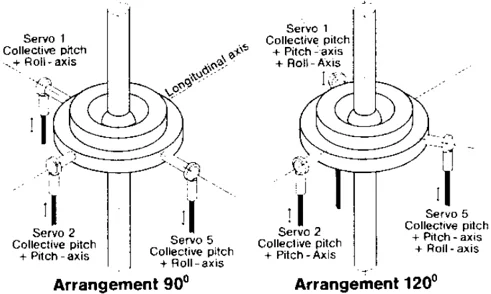
Fig. 34
The 90-degree arrangement is the simpler one. All three servos must first be assigned an equal part of the COLLECTIVE PITCH signal; the result is that the swashplate rises and falls evenly when the collective pitch control is operated.
For roll control only the two outer servos are operated, in this case in opposite directions. Finally the central servo alone provides pitch-axis control.
The 120-degree arrangement distributes the loads to the servos more evenly.
For collective pitch control all three servos again receive an equal part of the COLLECTIVE PITCH signal. For roll control, once again, only the two outer servos are operated, in opposite directions. For pitch-axis control, however, all three servos must work: the two outer ones work together, but in the opposite direction to the central one.
Even this is not the end of the matter: the servo movements must be different. The two outer servos, when required to produce a pitch-axis movement, deflect by the same amount. The central one has to move twice as far.
The same "HEAD-MIX" mixer is used for controlling the servos in both versions of the CPM rotor head:
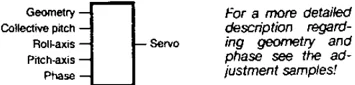
This mixer offers the facility to feed adjustable COLLECTIVE PITCH, PITCH-AXIS and ROLL-AXIS inputs to each servo. Any input which is not required – e.g. ROLL for the central servo – is simply switched off.
The servo assignment is simple:
Servo No. 1 controls HEAD-MIX, Servo No. 2 controls HEAD-MIX, Servo No. 5 controls HEAD-MIX.
Naturally, you still have to set the level and direction of the three inputs.
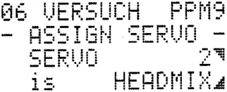
As an example to help you remember, the display will look like this (servo No. 2):
06 VERSUCH PPM9
- ASSIGN SERVO - SERVO 2 is HEADMIX
The 4-point linkage is, in practice, a 90-degree arrangement with 2 pitch-axis servos.
Your PROFI mc 3030 makes everything very simple. You assign "HEAD-MIX" to, say, servos 3 to 6. A 4-point linkage is supposed to offer advantages should a servo fail. Depending on the cause of the problem, it may then be possible to carry out an emergency landing.
You will find the necessary adjustments on page.
3. The "Heim" swashplate
This swashplate is also free to move axially, and collective pitch is achieved by this movement. However, it is only controlled directly by two (outboard) servos; when they move in the same direction the result is a collective pitch movement; when they move in opposite directions the result is a roll movement.
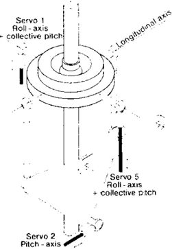
Fig. 35
A bellcrank is provided for pitch-axis control, and this is operated by the pitch-axis servo, which is mounted at right-angles to the rotor shaft. The bellcrank "floats", and thus moves up and down with the swashplate. The bellcrank "de-couples" pitch-axis control from collective pitch. By an ingenious design of the floating bellcrank pivot "flare" mixing is achieved automatically, so no special "flare" mixer is needed.
A special "HEIMHEAD" mixer is provided for the two "collective pitch/roll" servos.

Servo assignment is as follows: Servo No. 1 controls HEIMHEAD Servo No. 5 controls HEIMHEAD Servo No. 2 controls PITCH-AXIS
63
Transmitter control options for helicopter control systems
The transmitter offers a series of options for helicopter control systems, exactly like the fixed-wing control systems, which you can "activate", and adjust, when you need them.
If the term "transmitter control options" is not clear, please turn back to page 38 and read that section.
To some extent these options are identical to those for fixed-wing models; however, some of them are specific to helicopters.
The helicopter-specific options are explained in the following section. We assume that you are familiar with the others; you can read up on them on page 38 if you are not sure.
Here again, you are free to make use of as many of these options – or as few of them – as you wish.
The following options are available:
- "Collective pitch maximum" and "collective pitch minimum" in helicopter terminology. ** "Collective pitch-hover" in helicopter terminology.
The "collective pitch curve"
The term "collective pitch curve" refers to the relationship between the position of the collective pitch stick and the actual angle of collective pitch. Please refer to Fig. 36 here:
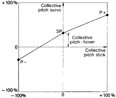
Fig. 36
When the collective pitch stick is set to "Centre", the helicopter is required to hover: this is the "Hover Point" (HP). The corresponding angle of rotor blade pitch is usually stated by the helicopter manufacturer, and is usually in the range +2 to +4 degrees; +3 degrees is a good starting point for your own experiments.
At the "maximum collective pitch" stick position the rotor blades are set to the maximum pitch angle for normal flying; here abbreviated to "P+". Its actual value is best discovered in practical flight testing, as it varies according to the motor power available (see below).
At the "bottom end" is the "minimum collective pitch" position – point "P–" (stick right forward). This setting is not critical and varies according to the model and the pilot. It is best for beginners to stick to the helicopter manufacturer's recommendation here; experts will have their own ideas.
You can adjust all three points independently of each other. In fact, these adjustments are no different from centre adjustment and separate travel adjustment of the collective pitch transmitter control, and you will find them in the menu under these terms. So: move to the "Adjust transmitter controls" menu; leaf through to the COLLECTIVE PITCH control. Set the hover point (HP) with the "Centre" option, and collective pitch maximum and minimum with the option "Travel \uparrow/\downarrow".
Note: As collective pitch is always adjusted in conjunction with the "throttle curve", we will have to come back to this subject in due course.
The "throttle curve"
The level of motor output, i.e. the position of the throttle slide in the carburettor, is usually derived from the position of the collective pitch stick for normal flying. The relationship between the two is termed the "throttle curve".
The options
You can select either of two types of curve: "3-point curve" Fig. 37; or "5-point curve" Fig. 38.
The philosophy concerning control and adjustment is the same for both curves:
The starting point is always the hover, as this is the most important basic adjustment. The collective pitch required for the hover is determined within close limits by the design of the helicopter. The required "throttle" setting for the hover is adjusted to match the collective pitch setting.
The next important "corner point" is maximum collective pitch. This cannot be set to any old value, however, as it depends on the maximum power of the motor. For this reason full throttle is set first, and the maximum possible collective pitch subsequently set to match it.
The last corner point is "minimum throttle" at low collective p n. On older transmitters this is where the "idle-u" or throttle pre-select function was used. To avoid confusion, we have also termed this point "IU". In this case the throttle is adjusted with the rotor "unloaded"; so that the rotor speed remains as nearly constant as possible.
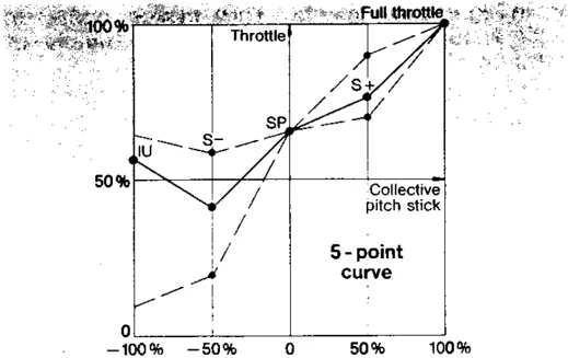
Fig. 37
The 3-point curve is simpler to set up, and is adequate in most cases. It also forms the basis for the 5-point curve. The 5-point curve offers a further, adjustable point above and below the hover point, so that you can match the required motor power more accurately to the characteristics of your motor. By setting these two points the "throttle curve" is endowed with either a progressive or a regressive shape. It also provides an easier method of increasing power for "negative collective pitch" – i.e. for aerobatics. The only drawback is that it gives you more work at the adjustment stage. The additional point in the middle, between hover point and maximum collective pitch, is termed "S+", the point between hover and minimum collective pitch "S–".
How to set the points
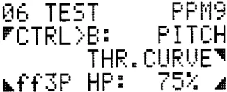
It is very helpful if you become familiar with the process of selecting and adjusting these curves, so we recommend that you carry out the following practice session. At the "Adjust transmitter controls" menu, select the COLLECTIVE PITCH control, and then select the "Throttle curve" option. The menu will look like this:
06 TEST FPM9 CTRL>B: PITCH THR.CURVE ff3P HP: 75%
Press the key; the "bottom left-hand corner" will flash. You can now select either "ff" or "fb", using the R key. Choose between "3P" and "5P" with the and keys. You can probably guess what the abbreviations mean already: ff3P = "Full throttle forward", 3-point curve fb3P = "Full throttle back", 3-point curve ff5P = "Full throttle forward", 5-point curve fb5P = "Full throttle back", 5-point curve
First the 3-point curve.
Stay at "ff3P" and press the key. "HP" (hover point) will flash. You are already at the point where you adjust the "hover throttle" setting. Use the or keys, or the Digi-Adjustor, to set the desired value; e.g. 75% (here 0% = throttle closed; 100% = full throttle). Move the stick back to the full-throttle position and hold it there. The display will now show "P+" instead of "HP"; and you can again set the correct value using the and keys, or the Digi-Adjustor.
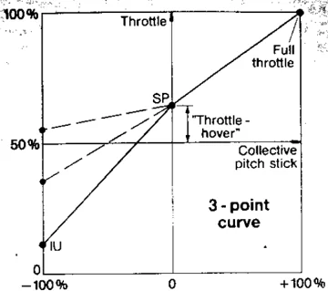
Fig. 38
Caution: you are now adjusting collective pitch maximum (not full throttle)! This method of adjustment is based on practical experience: full throttle is a fixed value, and maximum collective pitch must be set to match that value. If you want proof that you are actually setting collective pitch maximum, you can later move to the "Travel /4" option, and examine COLLECTIVE PITCH travel at "stick back". There you will find the same value set. Now to minimum throttle. Move the stick forward and hold it there; the display will now show "IU". You can now set the carburettor position for collective pitch minimum; e.g. 10%.
The 5-point curve
The setting-up procedure is similar to that outlined above. No doubt you realise that you must first select "5P" instead of 3P. If you have already set up a 3-point curve, then those values still apply. Otherwise you should set those three points first, as already described. You are sure to have discovered by now that the symbol "S+" appears in the display when you move the stick between "HP" and "P+". This is the additional point interposed between hover and maximum collective pitch. Hold the stick in that position and enter the value you think correct. Exactly the same applies on the "other side". Between "HP" and "IU" you will find "S–". Hold the stick in this position and enter the correct value with the and keys, or the Digi-Adjustor.
Adjusting the values in flight
Caution: never attempt to make changes in flight using the keypad. The risk of making a catastrophic error is too great! Always use the Digi-Adjustor for making in-flight adjustments. You don't really need to concern yourself with the details of adjusting this curve. If you rotate the Digi-Adjustor during a flight, it adjusts that part of the curve which corresponds to the position of the collective pitch stick at that moment – just as when setting up the curve in the first place. Nevertheless – a few words on the basic principles: The 3-point curve: When you rotate the knob, the minimum throttle position, the hover throttle setting or the collective pitch maximum setting will be altered, depending on the position of the collective pitch stick.
65
The 5-point curve: Here again, minimum throttle, the central part of the curve, or the collective pitch maximum setting is altered, depending on the position of the collective pitch stick (the centre part moves the three points S–, HP, S+ "in parallel"). In brief: Because of the "intelligent" method adopted for throttle adjustments, a single adjustor is sufficient for in-flight adjustments. This makes operation much simpler, and removes a whole bundle of stress from the pilot.
Now to recap: you have two useful adjustment facilities: on the one hand you can adjust the "throttle curve" as just described; on the other you can adjust collective pitch (the hover setting) at any time, using the collective pitch trim slider.
The "throttle slider"
The throttle slider can also be used to influence the throttle setting. There are two optional modes of operation. Normal mode of operation While you are in this mode of operation, the slider works as a "limiter" for the throttle. At any time the maximum throttle position is limited to the current position of the throttle slider; regardless of where your collective pitch stick is set, and regardless of how you have set up the throttle curve. In diagrammatic form:
 The whole thing in reverse: the helicopter is on the ground; throttle is "closed"; motor at idle. To take off push the throttle and revs high (collective pitch minimum); the "throttle curve" takes over, and with the throttle fully released the helicopter can finally be taken off by increasing collective pitch.
"Direct throttle" mode of operation
In many cases – for example, for adjusting the motor – the throttle needs to be adjusted without any automatic variation of collective pitch. In this case a switch is used to disconnect the collective pitch/throttle coupling: this is termed "Direct throttle".
In this mode of operation the throttle is adjusted directly, using the slider alone.
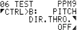
As usual, you have to tell the transmitter which switch you want to use to select "Direct Throttle". This is done at the "Adjust transmitter controls" menu, as a transmitter control option under COLLECTIVE PITCH.
First move to the "Adjust transmitter controls" menu, select the COLLECTIVE PITCH transmitter control, press the x key, and then leaf through with the ⊕ key until you reach the "Direct Throttle" option.
You will see this:
06 TEST PPM9
CTRL>B: PITCH
DIR. THRO.
OFF
Press the ▣ key first, then switch ON with the Ⓐ key, and finally select the switch you want to use with the ⊕ and ⊖ keys.
Now you can switch between "throttle coupled to collective pitch" and "direct throttle control" by means of the mechanical switch you have just selected.
Note:
The idle position of the throttle slider is fixed at "idle back", i.e. you cannot choose to reverse this channel, as you can with fixed-wing models. If you wish, however, you can adjust the throttle position at the "idle" position of the slider; this is done from the "Adjust transmitter controls" menu, at the THROTTLE control point, using the "Idle" option.
If you wish to set full throttle at "slider back", simply disconnect the plug from the corresponding slider inside the transmitter, and turn it through 180° degrees.
Auto-rotation
One switch can be dedicated as an auto-rotation selector.
When it is switched to auto-rotation, the transmitter does two things:
- It sets the throttle to a pre-selected setting (idle for practising; OFF for competition work).
- Any limit set on collective pitch travel at the transmitter control end is lifted (to make full collective pitch movement available). If you do not require this feature, adjust collective pitch travel at the servo only.
You will now probably be thinking: "What happens to the tail rotor?" Normally, because main rotor power torque is absent during auto-rotation, the mixing of collective pitch to tail rotor has to be removed.
The PROFI mc 3030 offers you a very simple and elegant feature: you simply need to move to the "Servo adjustment" menu, select "TAILROT", and select the "COLLECTIVE PITCH" input as switchable, then assign the same switch as for auto-rotation. If, for example, you select the switch "S5" for auto-rotation (we're just coming to that!), then make the COLLECTIVE PITCH input to "TAILROT" also switchable by "S5".
There is a further possible refinement to this; please read the note at the end of this section.
What you have to adjust: There are two points to remember here:
- Set the "auto-rotation throttle" to "Fixed Value"
- Assign the "auto-rotation" switch.
This should tell you where you will find auto-rotation: it is "hidden" under THROTTLE.
To do this, move again to the "Adjust transmitter controls" menu; then on to the THROTTLE control. Press the [key icon] key and select the "Fixed Value" option with the [+] key.
You will see the following display:
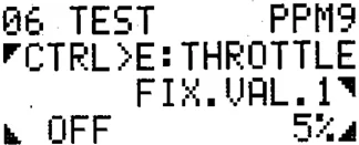
First: "auto-rotation throttle" Press the [key icon] key, then set the desired throttle setting in the usual way with the [+] or [-] keys, or the Digi-Adjustor; 0 - 10% is a good starting point.
Now define the auto-rotation switch: Press the [key icon] key and select the switch you want to use, using the [+] and [-] keys, as usual; for example the switch "S5". That's all there is to it.
Note that that the collective pitch input at collective pitch minimum and maximum must occur in the same direction. Servo adjustment menu, tail rotor servo, turn servo travel for collective pitch input once past "0".
Now to the actual problem. For auto-rotation the collective pitch input needs to be switched off. So, as usual:
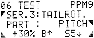
Assign the auto-rotation switch S5 to the "COLLECTIVE PITCH" input. Switch the "INPUT" to "FIXED VALUE" and assign the switch S5 to that too, but working in the opposite direction. To do this, with the input field still active (flashing), press [R].
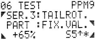
The net effect is that by operating the switch S5 you close the throttle, set collective pitch off, set a (variable) fixed value on, and switch to a second collective pitch travel.
Gyro suppression
"Suppression" means reducing or eliminating the damping effect of the gyro when the pilot wishes to override it. This is essential, as the gyro is only intended to reduce unwanted flight movements due to gusts etc., and not to counteract deliberate efforts on the part of the pilot.
There are three basic types of gyro:
- Gyros with no special facilities for allowing control from the transmitter. Some of these gyros also have a "suppression" effect, which is derived from the yaw control signal emanating from the receiver. These gyros have only one connection to the receiver. If you are using this type of gyro, you do not need to assign "GYRO" to a transmitter control nor a servo. There is nothing else to say on this type of device.
- Gyros whose sensitivity can be altered or switched off from the transmitter.
For this type of gyro a switched transmitter control is needed (e.g. channel "G"), which is then assigned to the "GYRO" function; you will also need a "servo" output by the name of "GYRO". This is where the sensitivity switch input from the gyro is connected. "Automatic proportional suppression" is of no relevance here.
"Gyro suppression" at the "GYRO" transmitter control is therefore set to "OFF".
- Gyros with proportional sensitivity, adjustable from the transmitter.
This is the type of gyro with which we are mostly concerned here. To control the sensitivity of the gyro a special signal is derived from the YAW signal in the transmitter, and this signal is then transmitted to the gyro via the servo output "GYRO": this is termed "automatic gyro control" or "automatic gyro suppression".
How suppression works
The transmitter generates a "suppress" signal which is proportional to the tail rotor stick position (regardless of the direction of movement). This signal is transferred to the "sensitivity input" of the gyro via a separate channel. The further the stick is moved, the more the sensitivity of the gyro is reduced; the less sensitive it becomes, the less effect it has, and the more the model responds to deliberate control movements. This effect is represented in Fig. 40. Fig. 40a shows the suppression signal, 40b the corresponding gyro effect.
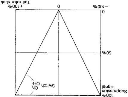
Fig. 40 a
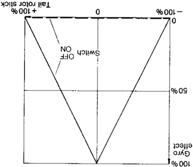
Fig. 40 b
The gyro usually has two adjustors which are used to set top and bottom limits on the sensitivity range. At the transmitter end a slider or a switch can be used to control "GYRO". If a slider is used, it becomes possible to adjust "gyro suppression" steplessly (not to be confused with infinitely adjustable suppression, which is proportional to stick movement!). In this case the range of adjustment is within the limits set on the gyro itself. Using a switch, on the other hand, you can "only" switch between the two limits set on the gyro. In practice, this latter facility has proved to be quite adequate; an infinitely adjustable setting is really one thing too many for most pilots to cope with. Please read the note at the end of this section in this connection.
The system in practice
We will suppose, as an example, that you have assigned "transmitter control H = GYRO" and "Servo No. 6 controls GYRO", as already described.
You must also ensure that a suitable switch is connected to Input H. It is essential that this is an ON/OFF switch with a 3-core lead (Order No. 7 5711, on/off, short toggle, or 7 5712, on/off, long toggle). No other type of switch can be used!
Now all that is left is to switch automatic suppression on. Move to the "Adjust transmitter controls" menu and leaf through to control H.
You will see this display:
06 TEST PPM9 FCTRL>H: GYRO SUPPRESS. OFF
Press the ▣ key, then . "OFF" is replaced by "ON"; and that's it.
Tip: Connect a servo (instead of a gyro) to the receiver "GYRO" output for this setting up process. You will then be able to see exactly how the suppression effect works:
With switch H set to OFF and the tail rotor stick at centre, the servo will be at one end-point. If you now operate the stick, the servo will run towards the other end-point, its movement proportional to the stick position; regardless of which side the stick is moved to.
If you now set switch H to ON, the servo runs straight to this end-point, and is not affected by movement of the stick: it receives the signal "gyro fully suppressed".
If necessary: Depending on your particular gyro, it may turn out that the suppression works "the wrong way round"; i.e. when the tail rotor stick is at centre, suppression is at a maximum, and it reduces as stick deflection increases.
In this case you need to move to the "Servo adjustment" menu.
Select "TRAVEL + REVERSE" and leaf through until you reach "Servo" No. 6. Press the ▣ key, then ⏎. You have now "reversed" gyro suppression.
Supplementary notes
- Minimum and maximum suppression
During this description we have assumed that the "corner values" for suppression (maximum and minimum suppression), between which you can move using the switch H, were set on the gyro itself, as explained at the beginning of the section.
If the gyro does not offer this feature, or you want to carry it out at the transmitter, then there is an alternative method:
Move to the "Servo adjustment" menu, select "TRAVEL + REVERSE", and set the "travel" of gyro suppression as you wish. When you adjust the travel (you can do it separately for both directions!), all you are doing is setting the corner values for gyro suppression (see Fig. 41).
68
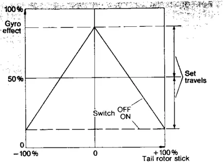
2. ON/OFF switch for gyro suppression
Just to complete the picture, we ought to point out that you could, in theory, assign a further switch to automatic gyro suppression, when you switch the function ON, as described above. If you continue with the ⊞ key after switching to ON, in the usual way, the transmitter offers you the familiar list of switches. In this way you would be able to switch the automatic suppression ON and OFF. However, apart from using up one extra switch on your transmitter, this offers absolutely no advantage; the same effect is achieved (better) by switch H, which we have assigned as the GYRO control. So please set up the system as described and do not assign a further switch to it.
Fig. 41
69
The Heli-Menu
The Recipe:
The transmitter controls
You may well have read through the information concerning fixed-wing models in order to understand how the system works (no bad idea), but please note that you must never adopt the transmitter control designations of the fixed-wing pilot. You may be tempted to think: aileron – well, that’s roll, and I can remember that easily.
You may be able to remember it, but that’s not good enough for your transmitter. Enter "Aileron", and it will give up with an error message, but usually not until you have finished your setting-up procedure.
That’s enough of the preaching.
Assuming that your transmitter is at the Status display, press the keys [M] [◄] [►] [▼] to reach ASSIGN CONTROLS. Activate the input field [▼] and press the [+] key to reach control "A".
"A" is the left-hand stick unit (the letters are printed on the transmitter). Release this input field with the [▼] key (field flashes). Leaf through the suggested control list with the [+] or [-] keys until you find the required function.
For example:
A controls ROLL; now press the [▼] key, and [+] once. In the display you see "B controls . . ." (something or other). Press [▼] again, and select the required function with the [+] or [-] keys or the Digi Adjustor.
B controls COLLECTIVE PITCH (or, if you prefer, PITCH-AXIS).
The procedure should be obvious now.
Continue this process until you have assigned functions to all the transmitter controls you need. Assign "- - - - - -" (Nothing) to controls you don't need. However, please don't assign the same function to two controls, e.g. "E controls throttle" and "H controls throttle"! On no account forget to assign "THROTTLE" to one of the sliders (E or F).
Now you will need your helicopter; or at least a receiving system complete with servos.
Go back to the "ASSIGN" menu with the [M] key, and branch to SERVO with [▼]. We will begin with servo No. 3.
The servo sequence is not binding, but please keep to our suggestions while we deal with our examples.
Servo 3 is the servo which controls the tail rotor. So press the [▼] key again (the servo No. will flash), and move to servo 3 with the [+] key. Now press the [▼] key to release the input field (field flashes). Use the [+] or [-] keys or the Digi Adjustor to select the "TAIL ROTOR" mixer. If you now move the yaw stick (and if your receiving system is switched on), the tail rotor servo will move. Move the collective pitch stick, and the same servo should also respond.
Normally you would assign all the servos in turn, and then make any adjustments necessary. This time, however, we will run through the procedure step by step.
Press the [M] key repeatedly until you return to Menu 1. Branch to Servo Adjustment with the [▼] key, press the [▼] key (CENTRE) and check that all servos are at 0%. If not, press [▼] (input field flashes), set them to 0% with the [+] and [-] keys, then leave the menu with the [M] key. Otherwise leave the menu immediately with [M]. Now branch to TRAVEL + REVERSE with the [▼] key. You will see this:
 13 HELI BOY PPM9
F SER.3: TAILROT.
PART : YAW
+90% A+ ON
Check the direction of effect of the yaw servo. If the servo rotates in the wrong direction, activate the appropriate input field with the [▼] key and press [R] once: the prefix will alter, and your tail rotor servo will be reversed for the yaw input.
Now the collective pitch input:
 13 HELI BOY PPM9
F SER.3: TAILROT.
PART : PITCH
+90% D+ ON
Press the [▼] key and [+] until COLLECTIVE PITCH appears. Work out in which direction the tail rotor must deflect in order to compensate for the torque effect of the main rotor. If necessary, reverse this for maximum collective pitch, as described for the yaw input.
A good starting point is about 30%.
Your tail rotor mixer requires a further input (press the [▼] key, then [+]).
FIXED VALUE (software revision 3.0 only) You only need this if your helicopter has a tail rotor which continues to rotate during auto-rotation. More on this under "Auto-rotation". The default for FIXED VALUE is "OFF". For now, leave it unchanged.
THROTTLE SERVO Let's move on to the next servo. Leave the Adjustment menu with the [M] key and move through Menu 1, Menu 2 and Assign to "Assign servos". Select servo 6, release the input field, and select the "THROTTLE" function using the [+] and [-] keys. Later, if you wish to set up a mixer circuit for aerobatic flying, you would select "DYN. THROTTLE" here. For our experiment we will stay with THROTTLE.
If you now push the throttle slider (the usual control) forward, and operate the collective pitch stick, your throttle servo should move.
Here again we need to set a basic adjustment, and select the THROTTLE CURVE.
Press [M] to return to Menu 1, then branch to the "TRANSMITTER CONTROL" adjustment menu. Select OPTIONS, then the Collective Pitch control. Using the [▼] selector key, move on to "THROTTLE CURVE". Release the input field with [▼] (ff 3 or similar flashes) you can select a 3- or 5-point throttle curve as preferred, using [+] or [-] keys, set the full throttle position with the [R] key (ff = full throttle forward, fb = full throttle back – more details on page 64). After releasing the input field you can set up the throttle curve with the help of the collective pitch stick.
For a 3-point curve: IU = Idle Up HP = Hover Point Throttle maximum (servo travel)
And for a 5-point curve: IU = Idle Up S– = Pre-idle point HP = Hover Point S+ = Pre-max. throttle point Throttle maximum (servo travel)
Note here that the throttle slider should be set to full throttle.
Now to the rotor head This is the only area in which model helicopters exhibit major differences. We will describe 5 different examples:
Schlueter Heim 3-point CPM 90-degree, with virtual rotation 4-point CPM with virtual rotation 3-point CPM 120-degree, with virtual rotation
If you wish, skip these examples if they are of no interest at present.
SCHLUETER That means no rotor head mixing (no electronic mixers). Return to Menu 1 with the [M] key, then move to Menu 2, to ASSIGN and ASSIGN SERVOS.
Now select: Servo No. 1 controls ROLL Servo No. 2 controls PITCH Servo No. 4 controls COLLECTIVE PITCH
Naturally this set-up will only work if you connect the servos to the corresponding receiver output sockets. Return to Menu 1 with the [M] key, then go to Servo Adjustment, TRAVEL + REVERSE. Check the direction of rotation of the servos and set up the approximate servo travels. To do this, activate the appropriate input field with [selector key], set the travels with the [+] and [-] keys (holding the transmitter controls at the corresponding end-points) for both sides of centre. You can reverse any of the servos with the [R] key if necessary.
HEIM When we speak of a HEIM rotor head (HEIMHEAD) we are referring to the classic version with the free-floating pitch-axis rocker (see also page 63). Return to Menu 1 with the [M] key, then move to Menu 2 and on to ASSIGN SERVOS.
Select (Assign) the servos as follows: Servo No. 1 controls HEIMHEAD Servo No. 2 controls PITCH Servo No. 4 controls HEIMHEAD
The two roll servos are connected to the receiver outputs 1 + 4, and the pitch-axis servo to output 2. Use the [M] key to return to Menu 1, then on to Servo Adjustment, TRAVEL + REVERSE.
First select servo 1 and the Collective Pitch input. Operate the collective pitch stick – look at servo 1 only – and check the direction of rotation of the servo. Reverse it if necessary.
Now look at servo 4. If the direction of rotation for collective pitch should be wrong, switch to this servo and reverse the collective pitch input.
Now for the two roll servos and the roll input: operate the ROLL stick and watch the servos. If the direction of rotation of one or both servos is incorrect, select the corresponding servo, then the roll input, and set the correct direction of rotation.
3-point linkage, 90-degree "HEAD-MIX" The 90-degree arrangement is swiftly losing popularity since the distribution of forces is very inefficient. Nevertheless, we will describe the application in detail.
We assume that you are at the Status display. Move to Menu 1 with the [M] key, then to Menu 2 with the [selector key] key, and then via ASSIGN to ASSIGN SERVOS.
There you assign the servos as follows: Servo No. 1 controls HEAD-MIX Servo No. 2 controls HEAD-MIX Servo No. 4 controls HEAD-MIX
Once more, to remind you: Release the SERVO input line with the selector key [selector key]. Select the servos in turn with the [+] or [-] keys. Release the Controls field again with the selector key [selector key], and select HEAD-MIX with the [+] or [-] key. Repeat the process with the second servo, and so on.
After you have assigned the rotor head servos, return to Menu 1 using the [M] key and branch again to SERVO ADJUSTMENT. Select Centre, and set the servo centres. Check here that the trim sliders and the transmitter controls are set to zero (0%).
Return to the "Servo Adjustment" menu with the [M] key, then branch to TRAVEL + REVERSE with the selector key [selector key].
Important:
-
It is essential that you set the direction of rotation of the collective pitch inputs to the head servos first. Operate the collective pitch stick, and watch the rotor head servos. Check carefully which servo or servos rotate in the wrong direction. Select the servo concerned, then the Collective Pitch input, and release the input field (selector key [selector key]). Press the [R] key to reverse the direction of rotation of that input.
-
Select the GEOMETRY input for all the rotor head servos in turn, and set the position of each servo in degrees. Switch to the input field using the selector key [selector key], and switch GEOMETRY "ON".
The right-hand servo should be 90 degrees, the rear servo 180 degrees, and the left-hand servo 270 degrees. If your pitch-axis servo lies in front of the swashplate, enter 0 degrees instead of 180 degrees for servo 2.
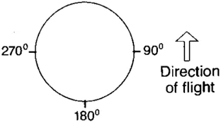
71