Example model: "F3B"
Memory No.: 8
The picture shows a typical F3B class competition model. The control system is quite complex. Each aileron and each flap is operated by its own servo. This makes "Quadro" and "aileron brake" (crow) control systems possible. In normal flight the ailerons support the camber-changing flaps, and vice versa; for landing the flaps are deflected fully down and the ailerons fully up ("aileron brake" function). Elevator compensation is mixed in with the camber-changing flap movement and the aileron brake system to compensate for pitch trim changes. Flap movement can be mixed in to support elevator movement. A radio-controlled towhook (towhook and aero-tow release treated as the same for control purposes) is an optional addition.
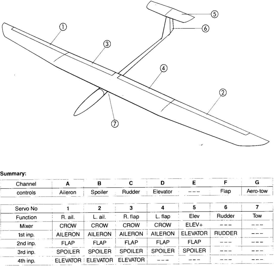
Summary:
ChannelA B CDEFG controlsAileron Spoiler Rudder Elevator---FlapAero-tow
Servo No1234567 FunctionR. ail.L. ail.R. flapL. flapElevRudderTow MixerCROWCROWCROWCROWELEV+--- --- 1st inp.AILERONAILERONAILERONAILERONELEVATORRUDDER--- 2nd inp.FLAPFLAPFLAPFLAPFLAP--- --- 3rd inp.SPOILERSPOILERSPOILERSPOILERSPOILER--- --- 4th inp.ELEVATORELEVATORELEVATOR--- --- --- ---
Note: when adjusting the mixing inputs it can be very useful to switch off any inputs which are not needed for the moment
Possible modifications: Control of the FLAP input via stick instead of slider Flap control with one servo only; in this case they cannot support the aileron function.
Example model: "CORTINA"
Memory No.: 9
"Cortina" is a typical example of a modern tailless glider. Control is achieved with two control surfaces per wing panel, each surface working as combined elevator and aileron (elevons). This arrangement makes it possible to achieve favourable lift distribution in all flight situations. The mixing ratios for elevator and aileron are different for the inboard and outboard elevons. A separate servo is required for each elevon. Airbrakes are included for height dumping and landing approach control. The aerotow coupling is actuated via a switched channel.
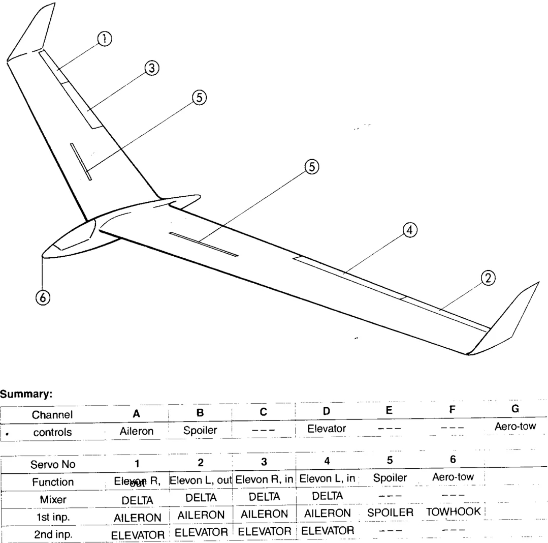
Summary:
ChannelA B C D E F G controlsAileron Spoiler --- Elevator --- --- Aero-tow
Servo No1 2 3 4 5 6 FunctionElevon R, outElevon L, outElevon R, inElevon L, in Spoiler Aero-tow MixerDELTA DELTA DELTA DELTA --- --- 1st inp.AILERON AILERON AILERON AILERON SPOILER TOWHOOK 2nd inp.ELEVATOR ELEVATOR ELEVATOR ELEVATOR --- ---
Possible modifications: Control of airbrakes via slider instead of stick. Use of a freely definable mixer instead of the "DELTA" mixer. Defined inputs then: AILERON, ELEVATOR, SPOILER. This arrangement would allow automatic elevator compensation for pitch trim changes caused by airbrakes.
23
Example model: "BIG LIFT"
The "Big Lift" represents a simple powered model. Ailerons and landing flaps are fitted in addition to the standard controls. An aero-tow release can be operated via the switched channel.
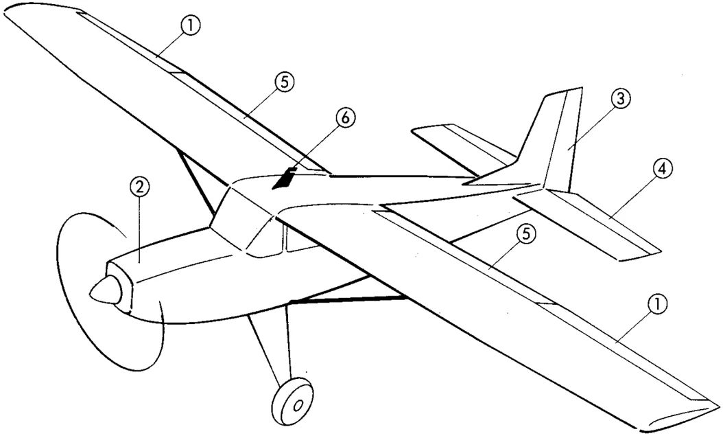
Summary:
| Channel | A | B | C | D | E | F | G |
|---|---|---|---|---|---|---|---|
| controls | Aileron | Throttle | Rudder | Elevator | Flap | --- | Aero-tow |
| Servo No | 1 | 2 | 3 | 4 | 5 | 6 |
|---|---|---|---|---|---|---|
| Function | AILERON | THROTTLE | RUDDER | ELEVATOR | FLAP | AERO-TOW |
| Switch | S1 | S2 | S3 | S5 | ||
|---|---|---|---|---|---|---|
| Use | DR, ail | DR, ele | DR, rud | Combi-Sw |
Adjustments: Transmitter control option: Dual Rate on aileron, elevator, rudder: 60%
Transmitter control option: throttle idle trim: –30%
Transmitter control option: flap travel: 0%, 100%
Combi-Switch: Aileron → rudder, following rate 100%
All servos: travel 100%, centre 0%
Possible modifications: Combi-Switch rudder → aileron, or switched off
Example model: "RC1/F3A"
Example of an F3A class competition model. The ailerons are each controlled by a separate aileron, to allow the optimum degree of differential to be set. Two spoilers are fitted, acting as airbrakes. Mixture control in addition to throttle control. A further servo can be fitted to retract the undercarriage via the switched channel. No mixers required.
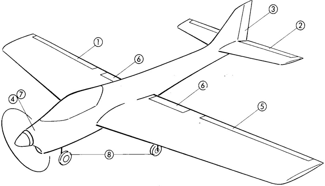
Summary:
| Channel | A | B | C | D | E | F | G |
|---|---|---|---|---|---|---|---|
| controls | Aileron | Throttle | Rudder | Elevator | Mixture | Spoiler | Undercarr. |
| Servo No | 1 | 2 | 3 | 4 | 5 | 6 | 7 | 8 |
|---|---|---|---|---|---|---|---|---|
| Function | L. AIL. | ELEVATOR | RUDDER | THROTTLE | R. AIL. | SPOILER | MIXTURE | UNDERC |
| Switch | S1 | S2 | S3 | |||||
|---|---|---|---|---|---|---|---|---|
| Use | DR, ail | DR, ele | DR, rud |
Possible modifications: Exponential servo travel instead of Dual Rates.
If "snap-flaps" are fitted instead of spoilers, use of "SNAPFLAP" mixer.
Example model: "MIRAGE"
Memory: No.: 12
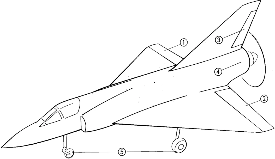
The "Mirage" is a simple delta model. It is controlled via combined ailerons/elevators (elevons), plus rudder and throttle.
The undercarriage can be retracted via the switched channel. The elevons are controlled with the help of a DELTA mixer.
Summary:
Switches: S1 = Dual Rates, aileron; S2 = Dual Rates, elevator Adjustments: Mixing input ELEVATOR: 40% (recommended starting point) Mixing input AILERON: 60% (recommended starting point) Throttle idle trim: -30% Dual Rates ELEVATOR, AILERON: 60% All servos: travel 100%, centre 0%
26
Example model: "HELI BOY"
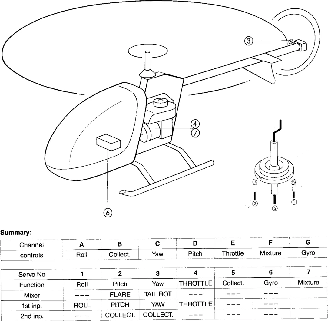
Example of a "simple" model helicopter, with swashplate having no axial movement. Collective pitch, pitch-axis and roll-axis are controlled by one servo each. FLARE mixer used for "flare" compensation. Simple "THROTTLE" assignment used for throttle instead of "DYN.THR.". This, of course, is just a starting point. Gyro assumed is a "suppressible" type. You can switch between minimum and maximum gyro effect using switched channel G.
Summary:
| Channel | A | B | C | D | E | F | G |
|---|---|---|---|---|---|---|---|
| controls | Roll | Collect. | Yaw | Pitch | Throttle | Mixture | Gyro |
| Servo No | 1 | 2 | 3 | 4 | 5 | 6 | 7 |
|---|---|---|---|---|---|---|---|
| Function | Roll | Pitch | Yaw | THROTTLE | Collect. | Gyro | Mixture |
| Mixer | --- | FLARE | TAIL ROT | --- | --- | --- | |
| 1st inp. | ROLL | PITCH | YAW | THROTTLE | --- | --- | |
| 2nd inp. | --- | COLLECT. | COLLECT. | --- | --- | --- |
Switches: S1 - Dual Rates, roll; S2 Dual Rates, pitch-axis; S5 - direct throttle
Notes: only the end-points of switched channel G are used; the centre position is skipped. 3-point throttle curve used.
Possible modifications: "DYN.THR." mixer instead of THROTTLE 5-point throttle curve "FLARE" mixer not used, only PITCH-axis on pitch-axis servo Gyro not used (different type of gyro)
Example model: "RANGER"
Memory No.: 14
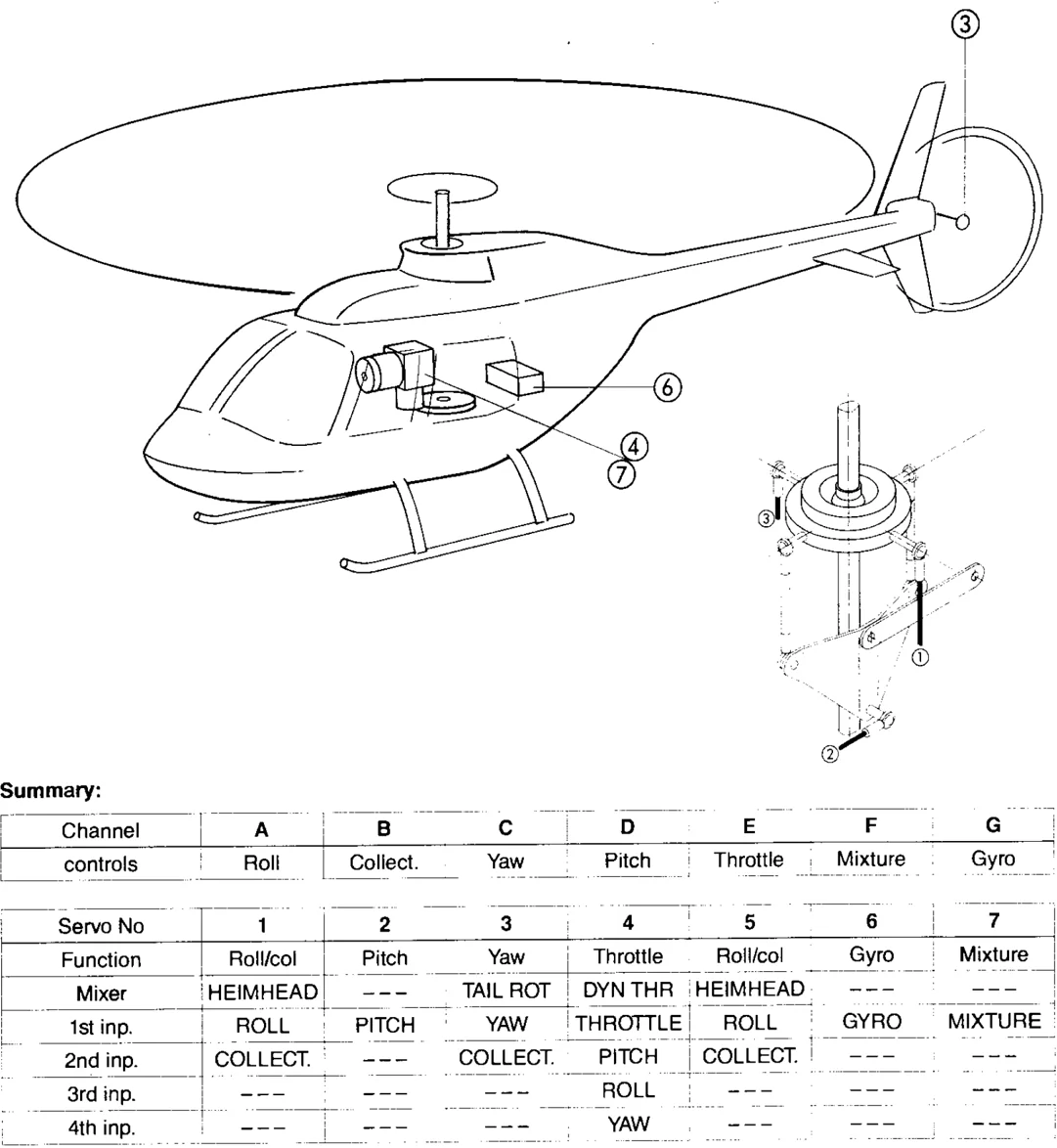
Example of a helicopter with the "Heim" swashplate actuation system. The swashplate is actuated by two roll/collective pitch servos, and the "HEIMHEAD" mixer is used. A separate servo provides pitch-axis control. In this example "DYN.THR." is used.
A "suppressible" gyro is assumed, which can be switched between maximum and minimum effect by means of switched control H. "Flare" mixing is not required, as "Heim" mechanics cater for this mechanically.
Summary:
Channel A B C D E F G controls Roll Collect. Yaw Pitch Throttle Mixture Gyro
Servo No 1 2 3 4 5 6 7 Function Roll/col Pitch Yaw Throttle Roll/col Gyro Mixture Mixer HEIMHEAD
TAIL ROT DYN THR HEIMHEAD
1st inp. ROLL PITCH YAW THROTTLE ROLL GYRO MIXTURE 2nd inp. COLLECT.
COLLECT. PITCH COLLECT.
3rd inp.
ROLL
4th inp.
YAW
Switches: S1 - Dual Rates, roll; S2 - Dual Rates, pitch-axis; S5 - direct throttle Notes: Switch control H must be installed (On/Off switch, 3-core lead) 5-point throttle curve used Possible modifications: 3-point throttle curve Gyro not used (different type of gyro)
Example model: "BK 117"
Memory No.: 15
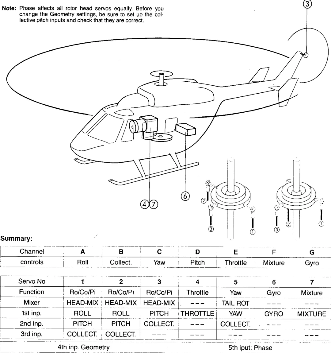
Example of a helicopter with "CPM" swashplate control system. The swashplate is controlled directly by 3 servos, arranged at 120 degrees to each other, which provide collective pitch, pitch-axis and roll-axis control. Three servos are used, in conjunction with the "HEAD-MIX" mixer. The throttle is assigned to "THROTTLE" ("DYN.THR." is an alternative). A "suppressible" gyro is assumed, which can be switched between minimum and maximum effect by means of switched control H. "Flare" mixing can be achieved by unequal collective pitch inputs to the "centre" and "outboard" servos.
Note: Phase affects all rotor head servos equally. Before you change the Geometry settings, be sure to set up the collective pitch inputs and check that they are correct.
Summary:
4th inp. Geometry 5th iput: Phase
Switches: S1 - Dual Rates, roll; S2 - Dual Rates pitch; S3 - auto-rotation; S5 - direct throttle Notes: Switch control H must be fitted (On/Off switch, 3-core lead) 3-point throttle curve used. Pitch input value for "centre servo" twice as great as for "outboard servos" (assuming 120 degree arrangement) Collective pitch input same for all three servos Possible modifications: 5-point throttle curve Gyro not used (different type of gyro)
"Assigning"

Why assign?
Assigning, or linking up, the transmitter controls, control functions and servos is the first and most important part of the setting up process which has to be carried out before you can actually use the equipment to control a new model. But don't run and hide – there's nothing very complicated waiting for you.
If you have owned another radio control system before the "PROFI mc 3030", you have probably already carried out this "assigning" process without realising it. If, for example, you have changed switches round, or swapped connectors over, in order to set up "aileron right" and "elevator left", then you have already "assigned" those functions to suit your preference.
We can differentiate between two forms of assigning: 1. Assigning the transmitter controls to the control functions The example we mentioned above falls into this category. Another example would be to decide that the left-hand slider is to control the model's airbrakes.
2. Assigning the servos to the control functions For example, this might mean that servo No. 2 (the servo connected to receiver output 2) is to operate the elevator; or in a helicopter that servos 1, 2 and 3 control a swashplate with a 120-degree actuation system.
On earlier radio control systems this "total adjustment" facility was not provided, and in fact it is not absolutely essential. But you will soon see that it is highly practical and useful.
The assigning procedure can also be extended to cope with the "mixing" of control functions; but we don't want to cover this point here. It is discussed in full on page 53, under the title "Mixers".
Why do we have to assign anything? This question is not all that easy to answer simply; nevertheless we will try. Here are some of the reasons: 1. Many of the transmitter's functions are carried out by a computer and its related software. The software is much more likely to work in a sensible way if it is given specific information. For example, "elevator" instead of "left stick, up/down". 2. Terms such as "left aileron" or "right collective" are familiar to any modeller. If you "tell" the transmitter, when assigning the servos, that servo No. 3 is the "collective pitch" servo, you can be certain that the collective pitch signal will always be available at socket 3 on the receiver, and that all mixing arrangements which involve that channel will automatically be carried out correctly. It prevents you having to worry about details which can be difficult to sort out.
In short: Assigning draws a clear line to follow: for you and for the computer in your transmitter.
How to assign the transmitter controls
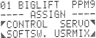
From the Status Display, move to the "Assign" menu using the key sequence M◢◣. We assume again that "BIG LIFT" is still the model in the current memory 01. The display will look like this:
01 BIGLIFT PPM9 ---- ASSIGN ---- ◥CONTROL SERVO◤ ◥SOFTSW. USRMIX◤
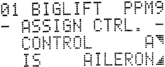
Select "CONTROL" (transmitter control) by pressing the ◢ key. This is what you will see:
01 BIGLIFT PPM9
- ASSIGN CTRL. - CONTROL A◤ IS AILERON◤
The transmitter responds by showing one of the nine controls (A to I) in the display. Press the ◣ key. The letter starts to flash. Now press the ⊕ key repeatedly until control "A" appears. Try using the ⊖ key as well.
A - D are the symbols for the stick units. The letters are also printed on the transmitter casing. For example, C is the right- left movement of the right-hand stick unit.
30
E and F are the two sliders; these letters are also printed on the transmitter casing.
G is normally (as standard) the "switched channel" No. 7.
H - I are not available on the standard transmitter. If you need these channels, you can install extra switches and connect them to the main circuit board sockets marked with those letters. See page 7.
By now this much should be obvious: in this line of the menu you select the transmitter control.
In our example, leave the "A" showing (flashing) and press the \blacksquare key.
The function which appears after the letter now starts to flash (in our example "AILERON").
Now things do get a little more difficult.
If you press the $+$ (or $-$) key to leaf through the functions, the transmitter will offer you the following functions in turn:
\begin{tabular}{llll} AILERON & ROLL & RUDDER (Ship) & AUX. 1 \ ELEVATOR & PITCH-NOSE & MOTOR (Electric) & AUX. 2 \ RUDDER & YAW & MOTOR 2 (El.) & AUX. 3 \ THROTTLE & PITCH & & AUX. 4 \ THR.2 (for 2 motor) & GYRO & & UNUSED \ SPOILER & & & \ FLAP & & & \ RETRACT & & & \ TOWHOOK & & & \ MIXTURE & & & \ \end{tabular}
As you see, these include all the most commonly used functions:
Columns 1 and 2 for fixed wing and helicopters; Column 3 for model boats and electric-powered models (including electric-powered aircraft). Column 4 is for the auxiliary functions 1 - 5. "AUX. 1-AUX. 4" are used when no other term "fits".
We will explain "UNUSED" – the last option – very soon!
We have "pre-defined" these functions for you so that you don't have to type anything in; all you have to do is select the right option. There is also another reason: if you select the terms from the list above, your "intelligent" transmitter works out what you are likely to ask next, and prepares itself accordingly.
The best way of coming to terms with this procedure is to carry out a sample assigning exercise.
We will assume a model glider with elevator, rudder, ailerons and spoilers.
The right-hand stick is to control elevator and aileron; the left-hand stick the rudder. The spoilers are to be operated with the right-hand slider.
It is obvious that the forward/back movement of the left-hand stick, the left-hand slider and the switch "No. 7" are not going to be used.
Now we can get going – provided that you are still at the "ASSIGN CONTROLS" menu.
First the elevator: Key \blacksquare; leaf through with the $+$ and $-$ keys until D appears (right-hand stick, forward/back). (The line under this the display already shows ELEVATOR, so there is nothing to be changed here)
Now the ailerons: Key \blacksquare; leaf through again using $+$ and $-$ until C appears (right-hand stick, left/right). Key \blacksquare; leaf through until AILERON appears.
Now the rudder: Key \blacksquare; leaf through until A appears (left-hand stick, left/right). Key \blacksquare; leaf through until RUDDER appears.
Finally the spoilers: Key \blacksquare; leaf through until F appears (right-hand slider). Key \blacksquare; leaf through until SPOILER appears. P.S.: if you wish, you can assign the stick function B to the spoilers instead of the slider.
Key \blacksquare; leaf through until SPOILER appears.
That's almost all there is to it. But what of the unused controls (B,E,G,H,I)?
There is a danger here that something has already been assigned to these controls when the memory was last in use – something which could cause problems. At the very least it would offend the sensitive glider guider to see THROTTLE against B, for example. You've guessed it: this is where UNUSED ("Nothing") comes in. As described above, select the controls B,E,G,H, and I in turn, and assign them to UNUSED, unless that has already been done.
This is typical of the way computers have to be treated: even when they are supposed to do nothing at all, you have to tell them expressly, otherwise they might do something unexpected!
The tidy-minded modeller should always assign unused transmitter controls to UNUSED, even when it appears to be unnecessary. It is always worth doing, as it can avoid considerable confusion.
Now you really are finished, and can leave the menu with the \text\textcircledM key.
Incidentally: In the example above we deliberately chose a complex sequence for the assigning process; you will soon find out just how quickly this can all be done.
And one more thing: You might have the bright idea of assigning two transmitter controls to the same function, e.g. "A = Aileron" and "C = Aileron". In that case the computer would not know which instruction it was supposed to act upon. For this reason our programmer has instructed it to consider the "last one" as the valid entry. In our example it would ignore the first entry "A = Aileron", and accept "C = Aileron".
- If you want to, you can skip a few pages at this point and do the following:
- Copy the results of your work into memory No. 02; see page 48.
- Switch memories; to No. 02. See page 50.
- Enter the name "FLAMINGO"; see page 50.
In the following examples we assume that you have done all this.
31
How to assign the servos
By "assigning the servos" we mean informing the transmitter which functions are to be carried out by which servo, i.e. you determine the servo functions.
To make it quite clear which servo we mean, each servo is designated with the number of the receiver output socket to which it is connected:
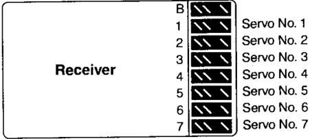
The servo connected to receiver output No. 1 is therefore servo No. 1, that connected to output 2 is servo No. 2, and so on.
At this point you have a more or less unrestricted choice of which number controls which function. However, we strongly recommend that you adopt a "standard" sequence, as this makes the whole business of setting up a new model easier to understand.
Our suggestion (adopted from the "ROYAL mc"): Servo No. 1: Aileron Servo No. 2: Elevator Servo No. 3: Rudder Servo No. 4: Throttle Servo No. 5: Aileron 2 (if separate aileron servos are used) Servo No. 6 - 9 : auxiliary functions
In special cases (e.g. wings with multiple control surfaces) you will need to arrange things differently; but more of that later.
Now the preamble is over, we can get down to business.
In the displays which follow we assume that you have moved to memory "02 FLAMINGO", as described at the bottom of page 31.
Starting from the Status display, press [icon] to reach the "ASSIGN SERVOS" menu. You will see this:
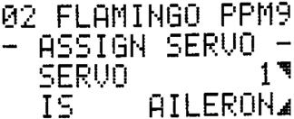
02 FLAMINGO PPM9
- ASSIGN SERVO - SERVO 1 IS AILERON
Press the [icon] key. The "1" starts to flash. Move on, or "leaf through", by pressing the + or - keys. The numbers rise to 9, then start again from 1.
As an example, stop at No. 3 ("3" flashing), and press the [icon] key.
The "3" will stop flashing, and the servo function in the bottom line will flash instead. Here again you can leaf through the options with the + and - keys and assign the correct function to that servo.
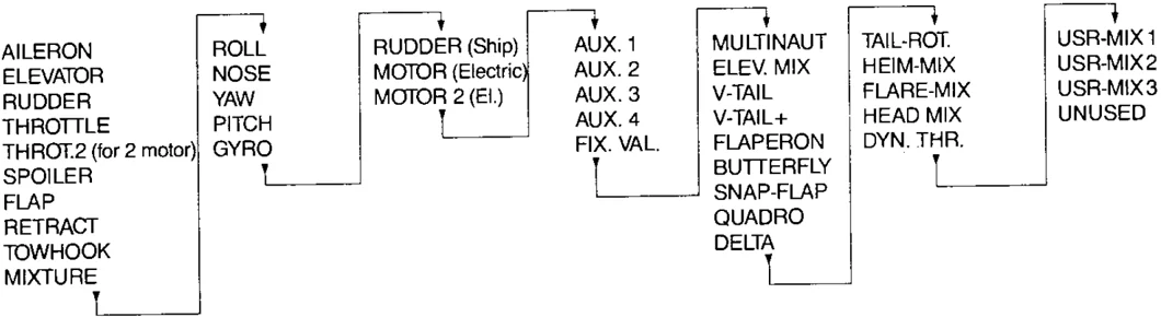
If you leaf through again with the + key, the transmitter will offer you a large number of further functions in sequence. The series runs as follows:
That's quite a lot to assimilate in one go. Let's take a closer look:
The "first division" includes the familiar standard control functions for fixed-wing aircraft and helicopters, as in the transmitter control assigning process. They are followed by the specialised functions for model boats and electric-powered models. As you have guessed, AUX.1 - AUX.4 are for special functions which do not fit into the usual pattern.
Now to the second group Here we meet with the "mixers", which you have probably been looking for in vain in this book so far. All the mixers listed here are stored in the transmitter in "ready-made" form, and just need to be invoked, or called up.
More on this in the "Mixers" section. Using our example, we will just explain why the mixers are included in the "Assigning servos" process. Let's look at the example of a "V-TAIL". As you probably know, the two control surfaces are each operated by one servo, and thus both servos are "V-tail servos". If you now assign the servos like this:
Servo No. 2 controls: V-TAIL; Servo No. 3 controls: V-TAIL,
then the transmitter automatically understands that it must send the elevator and rudder signals to servos 2 and 3. All you need to do after that is tell it how much of each signal to send.
You have assigned servos 2 and 3 as the "V-tail" "mixed control function".
Right at the end of the list, as in the earlier assignment table, you will see "UNUSED" ("Nothing") again – an apparently useless option. A servo which does "nothing" could really be left in the shop window – that's one way to save money. However, you will see later that there is a good reason for it, and that the "Nothing" option can be very useful.
32
And one more tip: If you connect a servo to a receiver output to which "UNUSED" is assigned, then the servo receives an accurate neutral position signal (and nothing else). You can use this to set the servo itself to its exact mechanical centre point.
But back to the more "normal" functions.
Don't be afraid of assigning one control function several times; the transmitter knows all about that. For example, let's discuss "electronically differential" ailerons, with 2 aileron servos: as you need two servos for this, you assign them as follows: Servo No. 1 controls: AILERON; Servo No. 5 controls: AILERON.
This ensures that both servos will receive the aileron signal. More on setting up aileron differential in the Section entitled "Transmitter control adjustment".
Let's imagine that you have a model with 4 ailerons, each of which you wish to be adjustable separately for travel and differential. You would then need 4 aileron servos. You could assign all four servos to the "Aileron" control function. The same applies to all the other control functions (even the "mixed" functions!).
Finally a practical example in abbreviated form. A model glider with elevator and rudder, differential ailerons, spoilers and aero-tow release (the "FLAMINGO" again).
First you make the connections at the receiver end: Elevator is operated by servo No. 2 Rudder is operated by servo No. 3 Ailerons are operated by Servos No. 1 and 5 Spoilers are operated by servo No. 4 Aero-tow release is operated by servo No. 6
Now to the assigning procedure, as described above: (Note: you will find that some of the servos are already assigned to the correct function when you select that servo No. Don't be put off by this. Just for practice, press the keys "round the clock" one time, until the function appears again. Of course, you never actually need to do this.) key; then leaf through with + key until "2" flashes. key; leaf through until "ELEVATOR." appears. key; move on to "3" with the + key. key; leaf through with the + key until "RUDDER" appears. key; leaf back to "1" with the - key. key; move to "AILERON" with the - key key; forwards again with + to "5" key; "AILERON" again with the key key; one back to "4", with the - key key; + key until "SPOILER" flashes key; leaf through with + until "6" flashes. key; + key until "TOWHOOK" flashes.
All done. Leave the menu with the M key; then M three more times, and you are back at the Status Display.
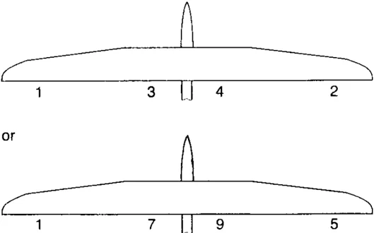
But take care: Always assign control surfaces alternately: one right, one left. E.G.
or
Correct: Alternate does not necessarily mean that the servo outputs must be directly sequential. If you do not keep to this rule, your aileron differential will work incorrectly.
Adjusting the servos
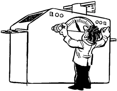
In case you are not familiar with the rather sloppy language we modellers are prone to use, "adjusting the servos" doesn't mean anything like our cartoonist seems to think it means (see above). It is more a matter of adjusting and setting up the "servo end" of the transmitter. The signals for each servo are produced by the transmitter, and since they are not modified at all after they have been transmitted, the effect of any adjustment is the same as if it had been made at the servo itself.
In the following section we will describe in detail the basic adjustments which can be made to the servos.
Reversing the direction of servo rotation (servo reverse) is certainly the most important aspect of this. Please note this point right now: the servos themselves are never reversed – think for a moment of a simple V-mixer: elevator correct, rudder incorrect. Now reverse the "servo": rudder is now correct, but elevator is incorrect. Morale: only reverse the mixer input! More on this later.
You can also adjust the neutral position of the servo "electronically" at the transmitter.
Finally we have the possibility of adjusting servo travel – separately for each side of neutral.
While reversing servos is almost a daily necessity, the two other facilities are more for special cases, and for the experienced modeller who wants to tune his system to a high level of refinement.
In this Section we are concerned only with these "simple" adjustments. There is a more complex side, which is concerned with mixers. This is explained in the Mixer section (page 53).
We will discuss this in conjunction with "02 FLAMINGO".
How to reverse the direction of servo rotation
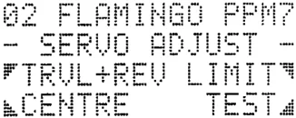
Starting from the Status display, press M [key] to reach the "Servo adjustment" menu.
You will see this:
02 FLAMINGO PPM7
- SERVO ADJUST - TRUL+REV LIMIT CENTRE TEST
Press the [key] key to select "TRAVEL + REVERSE"
After this you will see:
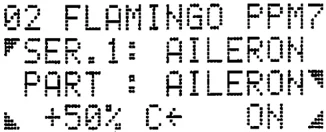
02 FLAMINGO PPM7 SER.1: AILERON PART : AILERON +50% C+ ON
Only the second line is of interest here, together with the lefthand corner of the fourth line.
First you have to tell the transmitter which servo you want to reverse.
Press the [key] key. The servo No. ("1") starts to flash. Now you can press the [+] and [-] keys to leaf through to the desired servo. Once you have displayed the one you want, press the [key] key. The percentage display (the set travel) begins to flash.
Please note: the travel display has a symbol in front of it – the prefix "+" or "-"; depending on how it was last set.
Now comes a typical example of how the [R] key is used: Press this key, and "+" turns into "-", or vice versa. That action reversed the servo. This was a simple, standard case, when the servo concerned has no mixed control function. We will cover this area in detail in the "Mixers" Section.
You leave the menu with the [M] key; and by pressing [M] twice more you return to your starting point, after yet another successful expedition into the land of the keypad.
Fatal error; or a special "feature"
Really this belongs to the "Travel adjustment" section, but this is where you will look for it.
How come this feature is normally an error?
You apply right – the servo runs to the right – so far, so good. You apply left – the servo runs to the right again. What's happened?
Now, what you have done is turn once past "0" when setting the servo travel. Turning it back past zero again reverses the movement and removes the problem.
If your servo now needs to be reversed, press [R] once.
This unusual feature is important for the helicopter pilot. For example: mixing collective pitch and tail rotor. In this case that is exactly what is required – regardless of the direction of collective pitch the tail rotor compensation must always occur in the same direction, proportional to the collective pitch deflection.
How to adjust the servo's neutral position
Within reasonable limits, you can adjust the neutral position of the servos connected to each receiver output.
What's the point of that?
Adjusting the neutral position can be useful: for example, if you want to use a servo of a different make with your new system. Different manufacturers use different standards, and you may find that the output arm of a rotary output servo will not be at the correct angle.
Another case might be that you find a servo's neutral position non-central for any reason, and there is no means of adjustment on the servo itself.
Never use this facility to make up for pushrods which have turned out too long or too short!
Generally speaking you ought to use this facility as sparingly as possible. It is easy to forget whether you have reset neutral positions or not, and this can lead to confusion, especially since there are so many other adjustment facilities which have a vaguely similar – but not quite identical – effect.
This is how you do it: Starting from the Status Display, press the appropriate keys to get to the "Servo adjustment" menu. You will see this display:
02 FLAMINGO PPM7
- SERVO ADJUST - ▸TRUL+REV LIMIT◂ ◥CENTRE TEST◣
Select the "CENTRE" menu point with the ◢ key. Now you are at the right place, and will see a display like this:
02 FLAMINGO PPM7
- SERVO CENTRE - ▸SERUO1: AILERON ◥CENTRE: +1.5%◣
First you have to select the correct servo. Press the ▣ key; the servo No. (in our example "1") starts flashing. Press the ⊕ or key to reach the servo No. you want. Once it is displayed, press the ◢ key. The value at the right of the bottom line starts to flash.
You can now adjust the offset with the ⊕ or ⊖ key to any point between +11% and −11% in steps of 0.1%, and then from 11% to 110% in 1% steps.
That's all there is to it. Press the Ⓜ key to leave the Servo adjustment Menu, and you return to the Status Display.
How to adjust servo travel
The transmitter offers the facility of adjusting the travel of each servo: separately for both sides of neutral.
What use is that? The simplest way of explaining this is to provide a few practical examples.
Example 1: The landing flaps of a large-span model aircraft are operated by two servos: one for each flap. Manufacturing tolerances in the servos have combined to produce a slight difference in output travel. The result of this is that maximum "down" on the flaps produces unequal flap movement, and the model tends to turn. You have two options: seek out two matched servos, with exactly equal mechanical travel, or utilise the travel adjustment facility.
A point to note here is that each servo must have "its own" receiver output; otherwise it is not possible to adjust the travel of each servo independently (use the facility of assigning multiple servos to one control function: page 32).
A similar case might be ailerons with superimposed camber-changing flap function.
Example 2: It is often the case that for competition use the travel of a servo must be exactly the same on both sides of neutral. Here again unavoidable manufacturing tolerances make it difficult to find a servo which fulfils this requirement precisely. In this case the remedy is to use the facility to adjust servo travel on one side of neutral only.
Example 3: If, for whatever reason, a servo of a different make is to be used with the system, there will be problems due to the different standards adopted by the two manufacturers. Travel adjustment solves this problem too (the difference in neutral position can be corrected by adjusting the centre position; see page 34).
And one more preliminary note, before we get down to business:
Here we assume that the servo has one "simple" control function; e.g. elevator or aileron without mixing, or undercarriage actuation. In "mixed control functions" the same procedure is used; but then it gets a little more complex, because in some cases only certain "inputs" of the overall travel are to be adjusted or shifted, while the others are to be left unchanged. More on this in the "Mixers" section.
But now to actually adjusting the travel. From the Status Display you get to the "Servo adjustment" menu by pressing Ⓜ and ▣ You will see this:
02 FLAMINGO PPM7
- SERVO ADJUST - ▸TRUL+REV LIMIT◂ ◥CENTRE TEST◣
Select "TRAVEL + REVERSE" with the ▣ key.
The first step is to select the servo you wish to adjust. Press the ▣ key. The servo No. ("1" in our example) starts to flash. Leaf through the servos with the ⊕ and keys until the correct number appears.
Select servo No. 3; in the example you will see this:
02 FLAMINGO PPM7 ▸SER.3: RUDDER PART : RUDDER◂ +100% A→ ON ◣
After the servo No. you will see the control function – a double-check that you have the right servo. The "Input" display in the next line down is of no interest at the moment, as it is only of significance where functions are mixed.
But now to the bottom line – this has something for us:

At the far right you may see "ON". This is only important for mixed functions; it shows whether that particular input is "switched on" or not at the moment. Forget that for the moment!
In our example you will see A → next to the value for travel. Move stick A to the left:
The right arrow turns into a left arrow. This display also takes account of the current position of the trim slider, so it may be that in your case you see a left arrow first, which turns into a right arrow when you move the stick to the right.
You will understand it now: this is the transmitter control which acts upon the servo you have selected. The arrow shows the direction in which the control is moved.
Now press the key. The "left-hand bottom corner" starts flashing.
Hold the stick at its left-hand end-point; as described above, you will see a left arrow. If you now press the or key, the travel value will change. Set it to "80%". Move the stick to the right-hand end-point (right arrow) and set the travel to "90%" in the same way. That's it for now.
Are you beginning to feel at home with the system? The servo travel which corresponds to moving the stick to the left is selected and then adjusted by "stick left". The servo travel which corresponds to moving the stick to the right is selected and then adjusted by "stick right".
If you now move the stick to right and then left you will see that the travel value alternates between 80 and 90%.
The prefix in front of the travel value shown is normally irrelevant when adjusting servo travel (there is an exception: see below); it shows whether the servo's whole travel is reversed; see also page 34: "Servo reversing".
With the work completed, leave the Servo adjustment menu by pressing the key; then twice more to return to the Status display.
Now a few more points:
It makes no difference how far you move the sticks when making these adjustments; the only important point is the direction in which the arrow faces. If it is not likely to confuse you, you can move the corresponding trim slider instead, and leave the stick at centre.
The same applies to all servos/control functions. For functions which correspond to forward/back stick movements, the right and left arrows are replaced by up and down arrows.
All percentage values refer to the normal nominal travel of the servo concerned; this is usually 45 degrees (although there are exceptions).
There is no reason why you should not set extreme travel adjustments. For instance, in the example above you could set the left travel of the stick to zero; in that case the servo would not move at all when you move the stick in that direction. You can even set the travel to less than zero, i.e. a negative value, by simply pressing the key. The servo will now move to the right when you move the stick to the left, as well as when you move it to the right (as you have not changed that side of neutral). Quite why you might want to do that is beyond us just at the moment!
Caution - a trap for the unwary! Please don't set the travel to zero on both sides of neutral. The result would be that the servo does not move at all. If you do this for some reason, but then forget that you have done it, you will have an apparently non-functioning channel, which will drive you uncomfortably close to the edge of insanity... The other side of this coin: if you get "nothing at all" at one receiver output, check first whether you have set the servo travel to zero by mistake!
Servo travel can also be set to more than usual: a setting of up to 110% is possible. We do not recommend using this facility excessively, as, with certain types of servo (linear output servos in particular) you run the risk of jamming the mechanics mechanically. You might also like to bear in mind that an output travel of more than 45 degrees usually provides very little extra movement, due to the geometry of standard mechanical linkages.
36
Adjusting the transmitter controls
In the previous section we discussed setting up the "servo end" of the system; now it is time to concern ourselves with adjusting the "signal source", namely the transmitter controls.
An important difference
The systematic differentiation between "transmitter end" and "servo end" is an important characteristic of the philosophy behind the PROFImc 3030. For this reason we would like to explain this difference once more in brief, before we get down to business.
Once again, examples are the best method of explanation.
If you want to reduce the effectiveness of the elevator, it may seem to make no difference whether you reduce the travel of the elevator stick or electronically reduce the servo's travel.
But this is only true if the application is of the simplest possible type, i.e. no signals are "derived", "mixed" or otherwise influenced. If we assume in our example that there are two elevator servos (e.g. one for each elevator panel), then, if we insist on working at the "servo end", the travel of both servos would have to be reduced separately.
Things get a little more difficult if we suppose that elevator movement is also intended to involve the camber-changing flaps. In this case we would need to reduce the "mixed elevator input" to the flaps also; otherwise the ratio of the mixed functions would alter. However, if we reduce the movement at the transmitter end, things are much easier: all we have to do is reduce the elevator stick signal; everything that is affected by or derived from that signal is automatically reduced at the same time.
A second example would be differential aileron movements where two separate aileron servos are used. As differential is nothing more than unequal servo travel on different sides of neutral, it would be possible to adjust the servos themselves individually. But it is easier if we produce the two aileron control signals at the stick by a "differential circuit", as we can then set the degree of differential with one single adjustment.
Correct assignment is important! If the differential movement of your ailerons works the wrong way round, please see page 33.
A further example is reversing the direction of rotation: When we reverse the direction of movement at the transmitter control, then this reverses the rotational direction of all the servos (or, more precisely, all the inputs from this control) which are operated by this transmitter control. This is not the same as reversing the servo itself.
You can probably see the principle already: We have a "flow of signals", starting at the transmitter controls (the signal "source"). The various influences on the signal then follow – mixing arrangements, signal splitting etc. The servos and the control surfaces which they operate are the final link in the chain.
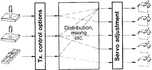
If we alter something at the source – the transmitter controls – then that change affects everything which is influenced by that control.
Each transmitter control is assigned to a particular control function (elevator, aileron, ...). If a change is made to the transmitter control, that change affects the entire control function – and this is exactly what is usually required.
One more example: if you want exponential aileron control on a model fitted with "quadro-flaps" (four separate wing control surfaces), then the entire "aileron" function needs to be altered, i.e. all four servos at once.
If, on the other hand, we try to set that up by adjusting one of the servos, the change will only affect that one servo.
To recap: Adjustments at the transmitter control affect the entire control function. Adjustments at the servo end affect that servo only.
37
The transmitter control options
Now it's time to discuss the transmitter control adjustment facilities. The complex-sounding term "transmitter control options" is simply an overall description of the adjustment facilities which are provided for the transmitter controls. You are probably familiar with them already from other radio sets. For example: Dual Rates, Exponential and so on.
These options are supplied "ready made" in your transmitter, and are offered via the "Transmitter Control Adjustment" menu. No "assigning" is necessary. In order to activate an option, you simply need to "leaf through" to the appropriate point in the menu, then set the value you want. If you do not need a particular option, just set its value to 0% (or 100%, depending on the type of function).
Not all options are available for all transmitter controls; that would not make sense (who would want a retractable undercarriage with exponential travel?). The availability of the options is based on practical requirements:
Dual Rates and Exponential: Ailerons, elevator and rudder.
Travel, adjustable separately on both sides of neutral: All functions, except ailerons and throttle.
Travel, symmetrical adjustment: Ailerons only.
Centre adjustment: All functions, except throttle, flap and spoiler. Idle trim: Throttle and spoiler only.
Differential: Ailerons only, provided that at least 2 servos are assigned to this function.
Fixed value: Not for ailerons, elevator, rudder or throttle; all other functions.
You can also use 2 or more of these options together; for example, exponential and Dual Rates on aileron (if you think this will be to your advantage), plus differential and centre adjustment also. All you need to do to apply these options is increase the value in the display. It's all explained below:
In the case of helicopters there are further possibilities; we will discuss these in detail on page 61.
But now, finally, to business.
How to set transmitter control options
As we are now talking about adjusting the characteristics of transmitter controls, move to the "Transmitter Control Adjustment" menu.
From the Status display you reach the menu with the key sequence [M] [◄] [▼]. If we return to the first example – 01 BIG LIFT – you will see this display:
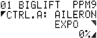
Press the [▼] key. The transmitter control letter (in our example "A") starts to flash.
Now you can "leaf through" the options with the [+] and [-] keys. The various transmitter controls will appear one after the other; at the same time the display shows which function they operate.
Select, for example, "Elevator" (leave it flashing) and press the [▼] key.
The option "Expo" flashes in line 3.
You can now leaf through again, using the [+] and [-] keys, and the transmitter will offer you all the available options in turn.
The "Dual Rate" option
Leave "Dual Rate" displayed in the above example. The display will look like this:
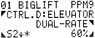
May vary
Press the [▼] key. The value at bottom right flashes. You can alter it using the [+] and [-] keys. 100% is full travel, i.e. no throw reduction when the switch is operated; at 50% it will be reduced to half when the switch is operated. You have a set up "Dual Rates" for the elevator.
But wait a moment – there's something else!
In the bottom left corner are more symbols. Press the [▼] key: and this area of the display will begin to flash. Press the [-] key until "ON" or "OFF" is shown there. This much will probably be clear: this shows whether the option is switched on or off. You can switch between ON and OFF by pressing the [R] key.
Switch to ON, then press the [+] key. You will see this:
This part is also easy to understand: Dual Rates is one option which requires a switch, namely to switch between full and reduced travel; and you have just selected the switch S1 for this purpose. If you don't like this arrangement, press [+] again and S2 will be selected. You can continue up to S5 – even the Teacher/Pupil switch can be used (if you insist).
You are free to choose which switch it "ought to be".
However, it is important that you establish your own "personal layout", otherwise sooner or later you will find yourself totally confused.
Our suggested layout: Dual Rates, aileron: S1 Dual Rates, elevator: S2 Dual Rates, rudder: S3
The asterisk
And now an explanation of what the symbols after the switch mean: this is a real connoisseur's refinement:
Let us suppose that you have selected S2, and that "S2" is still flashing. Press the Ⓚ key. The small arrow after "S2" is reversed. You have now reversed the switch. And the point of that? Well, many pilots want Dual Rates "active" when the switch toggle faces away from them; others the opposite way around. You can select it yourself.
(Caution – don't turn the switches themselves round! They must be installed as dictated by the Transmitter Control Test on page 73; otherwise the whole arrangement will be upset.)
The asterisk (star) which appears after the arrow in one of the two positions shows that the switch is "ON" in this position.
This entire "switch corner" only appears on the screen when you are dealing with an option which requires a mechanical switch; for fixed-wing models these are "Dual Rates" and "Fixed Value".
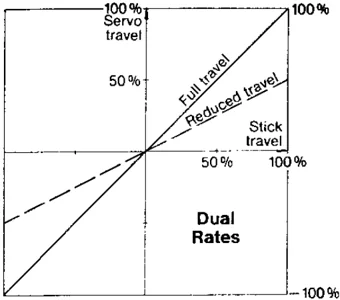
Fig. 20 Dual Rates reduces servo travel equally in both directions, and is controlled by a mechanical switch.
The "Expo" option (exponential travel)
An exponential curve is one which increases disproportionately the further it moves away from zero. Its effect on a control function is that the servo makes small movements around centre, but the further the stick is moved, the more servo travel increases. At the stick's end-point, the servo reaches its own normal end-point.
In practice the result is that the pilot has very fine control of the model in normal flight, but still has available the large control surface movements which are occasionally required.
Selecting and setting up this option are carried out exactly as described for Dual Rates above, so we do not need to repeat the information in detail.
Exponential is not switchable; so there is no mechanical switch to select. 0% exponential means normal, linear control characteristics. 100% is the maximum possible exponential deviation from normal.
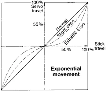
Fig. 21
The "travel adjustment, separately for both sides" option
This facility allows you to adjust maximum servo travel separately for each of the two directions of the stick.
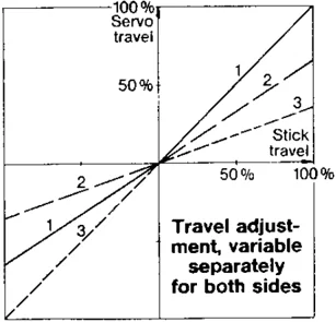
Fig. 20
A typical application would be in a model whose control response is not equal in both directions, perhaps for aerodynamic reasons.
It is available for all control functions with the exception of "throttle" and "ailerons". This option is found in the "Transmitter Control Adjustment" menu. The following symbol will appear in the third line:
TRAVEL+/-
Symbol for symmetrical adjustment
The adjustment process itself (line 4):
ON SIDE→ 80%
39
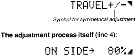
Press the ☑ key; the set value at bottom right starts to flash. Move stick C to its right-hand end-point; the small arrow before the displayed value will face right. If you adjust the travel with the ⊕ and keys, this setting applies to travel to the right of centre. Move the stick to the left end-point; the small arrow will point to the left. You can now set travel to the left (again using the ⊕ and ⊖ keys). 100% = maximum possible travel; 0% = zero travel. That was simple enough. One further point to note:
In the adjustment process just described it makes no difference whether the stick is at full right or full left movement. The crucial point is that the small arrow points in the correct direction. All you need to do is move the stick slightly to the desired side; even moving the trim slider is enough. Just watch the small arrow; it indicates whether you are adjusting the right-hand or left-hand travel. In the case of "fore/aft" movements or switches small up and down arrows appear.
The "symmetrical travel adjustment" option
This option is only available for ailerons. A travel adjustment facility for both sides separately would make no sense here; with two differential aileron servos the effect would be the same as if differential had been applied. If you have already tried out some of the options described above, you will have no trouble setting up this function; it is carried out in exactly the same way. Here again: 100% = maximum travel; 0% = no travel
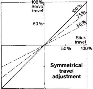
Fig. 23
The "Centre Adjustment" option
This is available for most control functions. It is used to shift the centre position of the transmitter control "electronically"; it has roughly the same effect as moving the trim sliders. The maximum travels which you have set are not influenced by the centre adjustment (i.e. it works in the same way as the "centre trim" system used by the trim sliders).
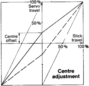
Fig. 24
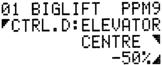
The adjustment range is up to 100%, i.e. as far as the end-point of the corresponding transmitter control. The adjustment procedure is simple: Move to the "Transmitter Control Adjustment" menu. Let's look at transmitter control D = Elevator as an example. First press the ☑ key and then leaf through until "Ctrl D:ELEV" appears. Press the ☑ key and leaf through with the ⊕ key until "Centre" appears in line 3 (flashing). You will then see this:
01 BIGLIFT PPM9 FCTRL.D:ELEVATOR CENTRE -50%.
Press the ☑ key; the value displayed at bottom right will flash. You can carry out the centre adjustment you want, using the ⊕ and ⊖ keys. Once you have completed the adjustment, return to the Status display with the Ⓜ key. Here are two more examples of typical applications for this option. Example 1: You have seen that it is possible to offset the centre by up to 100%, i.e. to one end-point. If you select such an extreme setting – in this example for one stick axis the associated servo does not move at all when the stick is moved to one side. When it is moved to the other side the servo carries out its full movement. This facility could be used for a glider with airbrakes: the brakes are extended when the throttle stick is moved back from the centre position. Over the entire "forward" half of the stick travel the servo does not respond at all, and stays at full movement. You now have full servo travel controlled by half the stick movement. Example 2: perhaps the most common application! With a well-built and carefully trimmed model the position of the trim sliders is not usually changed in flight, or only very slightly. If you adopt the position of the trim sliders as your centre adjustment, you will not need to alter the trims when you change models; the basic setting of the trim sliders is then always the centre position.
40
Caution: do not use the transmitter control centre adjustment facility to "centre up servos". There is a separate facility provided for this (see page 34).
The "Idle Trim" option
This option is only available for the "THROTTLE" control function (or THROTTLE-2). Its effect is that the throttle stick trim slider is only effective when the stick is at its "idle" position. Its effect is steadily reduced towards the centre position of the stick. In the whole of the full-throttle "half" of the stick arc (especially at the "full throttle" end-point) the trim slider has no effect.
The practical advantage of this option is that you can adjust the idle setting of the carburettor without affecting its full-throttle position.
Selecting and adjusting this option is the same as for the other options already described.
Adjustment range: 0% in the display: the "throttle" trim slider has no effect. Scope for errors here – take care! 100% in the display: the "throttle" trim slider adjusts the idle position within the whole of one half of the stick arc.
In practice (special cases excepted) a value of 20 to 30% is a sensible setting.
One further note: Normally the idle position of the throttle stick is "stick back". If you want it the other way round (e.g. for a helicopter), press the Ⓡ key once at the adjustment stage. This reverses the entire stick function; idle is then "forward". This is indicated in the display by a minus sign (-) in front of the set value, instead of a plus sign (+). If the servo then rotates in the wrong direction, reverse it as described on page 34.
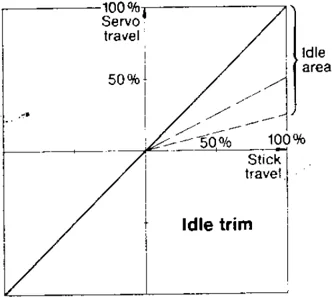
Fig. 24
The "Differential" option
This option is only available if a transmitter control has been assigned to the control function "AILERON" at the "Assigning" stage, and if at least two servos have been assigned to "aileron". In all other cases differential makes no sense, or can be replaced by the option "Travel adjustment separately for both sides".
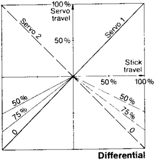
Fig. 24
To explain how this works, we will take another example. The transmitter controls and servos have been assigned as follows:
Transmitter control A = AILERON; servo 1 = AILERON; servo 5 = AILERON
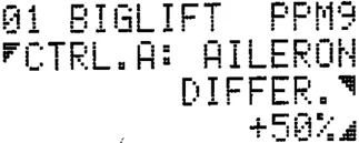
Starting from the Status Display, move to the "Transmitter Control Adjustment" menu. Press the ▣ key and leaf through with ⊞ until you see "DIFFER." in line 3, flashing:
01 BIGLIFT PPM9 FCTRL.A: AILERON DIFFER.▮ +50%▮
It is vital that the servos are assigned correctly, otherwise the differential movements will not be correct (see page 33).
Press the ▣ key; the value at bottom right will flash. You can now set the desired degree of differential using the ⊞ and ⊟ keys.
The figures mean: 0%: no differential; same movement up and down for both servos. 50%: the "down" movement is only half as large as the "up" movement. 100%: maximum differential; each aileron moves up, but does not move down at all.
You don't need to worry about anything else when setting up differential. The differentiated control signals are sent to the two servos automatically.
When setting the degree of differential you can "reverse" the differential with the Ⓡ key.
You will find that it is possible to set up differential ailerons correctly, regardless of your installation, by using this option in conjunction with reversing one or both servos (see page 34). We cannot give general guidelines, however, as there are so many possible variations in model design and radio installation.
41
One more tip (which also applies to other adjustments): It is sometimes easier and quicker to find exactly the right settings by carrying out "in flight" adjustments.
This is very easy using the Digi-Adjustor: Before starting a flight, move to the appropriate menu as already described, and select "Adjust Value" as described above; but this time don't leave the menu!
The Digi-Adjustor is connected "in parallel" with the \oplus and \ominus keys, and has exactly the same effect, namely of adjusting the degree of differential. All you need to do in this case is to rotate the Digi-Adjustor while the model is flying (don't look down at it!) until you are satisfied.
Land the model, then leave the menu by pressing the [M] key (everything gets stored automatically – there's nothing more to be done).
Caution! Although it is theoretically possible, you should never attempt to make changes via the keypad while the model is flying. You would have to take your eyes off the model to find the right key; and if you made a mistake, the results could be catastrophic!
The "Fixed Value" option - what's that?
"Dual Rates", "Exponential" and so on are terms familiar to the advanced modeller. He may not be on such close terms with "Fixed Value", however.
The simplest method of explaining it is to describe an example:
Imagine a model with camber-changing flaps which are operated by the right-hand slider = transmitter control F. Travel has been reduced (using the "Travel" option) so that full flap movement is in the range $-5$ to $+7.5$ degrees at the two slider end-points (this is not necessary to use "Fixed Value", but it does show up the usefulness of the option).
Now, on this model there is a specific flap position ($+15$ degrees) which is only needed for a particular flight situation (say, launching). Wouldn't it be nice if we could move the flaps to this fixed position with a switch, then return to normal operation again afterwards?
In order to achieve this it would be necessary for the switch to override the "normal" flap control signal, so that the flaps take up a pre-set, fixed value.
This is what "Fixed Value" is all about.
"Fixed Value" brings the control function to a pre-set fixed value when the associated switch is operated, and overrides the transmitter control itself.
There are therefore two things to set up: First, of course, the Fixed Value itself (in % of full travel). Secondly, the switch which is to "activate" the Fixed Value has to be selected. Adjustment is carried out in a similar way to that described above for "Dual Rates".
Here is another example:
We will assume that you have assigned the controls as follows: Transmitter control F = AUX.1; Servo 6 = AUX.1.
This means that the right-hand slider controls the servo connected to receiver output 6.
Move to the "Transmitter Control Adjustment" menu. Select Transmitter Control F: Aux.1.
Press the [■] key; then \oplus again, until "FIX.VAL." appears.
You will now see this display:
03 TEST PPM9 FCTRL.F: AUX:1 FIX.VAL.1 OFF 50%
Selecting the Fixed Value switch: In our example this is to be the switch S5. Press the [■] key; the display in the bottom left-hand corner will flash. It will probably show "OFF". Press the [R] key; "OFF" turns to "ON".
Leaf through with the \oplus key until "S5" appears (after it you will see an arrow and possibly an asterisk). Operate the switch S5; at one of the two positions the asterisk must appear. This means that the switch is set to "ON".
Adjusting the Fixed Value itself: Press the [■] key; the value shown in the bottom right-hand corner starts to flash.
You can now adjust the "Fixed Value" with the \oplus and \ominus keys. 0% means one servo end-point; 100% the other end-point. For example, if you set the value to 75% this means a position half-way between centre and one end-point.
Now you can carry out a practical test to see how the "Fixed Value" function works: when switch S5 is "Off", the servo can be controlled in the normal way with the slider. When set to "On" the servo runs to the position you have just set.
If you now want the switch to work the "other way round", press the [■] key again; "S5" will flash. Press the [R] key, and the arrow after "S5" will be reversed, and you will find that the direction of switch actuation is also reversed.
Important note for F3B flyers: When "leafing through" the options you may have noticed that there is a further option "Fixed Value-2". You can, in fact, set up two "Fixed Values" (Fixed Value and Fixed Value-2) which you can select at will.
For example, you could set up two pre-set positions for camber-changing flaps on a glider: "Tow" and "Speed".
In order to exploit this option, you will need to use the special 3-position switch "SI". If you use the switch I for this purpose, you must not assign it as a transmitter control for normal usage; i.e. I controls = ----- (Nothing). More on this on page 78.
If your brain is still functioning clearly, this is a good time to present a further refinement of this transmitter: An alternative method of operating many switched functions is to use a momentary switch (or press-button), instead of a normal toggle switch. The optional "stick press-button" is one example, or the momentary switch which is recommended for operating the stop-watch.
In the following we assume that you have connected a momentary switch of this type to "S4".
Press the key again. Go past "S5" with the + key; after the displays "LS", "Gx" (the x stands for the letters A - I) and "SI" the symbol S1 appears again, but this time followed by the symbol instead of the arrow. This indicates that a momentary switch is now "expected".
Press the + key again until "S4" appears.
Press the momentary switch "S4". Servo No. 6 will run to the pre-set Fixed Value. Next time you press the button the servo responds to the slider again, and so on.
In this way you can use the momentary switch to release or activate a function in the model which then remains "on" or "off" until you press the button again.
Caution! If you set up this option you can no longer see at a glance the current state of the model, i.e. from the position of the switch toggle. For this reason we only recommend using this facility for a non-critical function, or a function which works in a definite and obvious sequence; for example "undercarriage retracted/extended" or "smoke generator on/off".
FIXED VALUE again You can also assign a servo directly to a FIXED VALUE, regardless of what we have just said. This then functions as a virtual control. Using any assigned function switch you can run the associated servo to and fro between the two positions you have chosen.
The "Normpos" option
This option serves a special purpose and is only of significance in conjunction with mixers. When you extend spoilers or flaps it is often desirable to compensate for the change in pitch trim which occurs. To achieve this, part of the spoiler signal is bled off to the elevator servo.
The following problem then arises: The "idle position" (brakes retracted) of the transmitter spoiler control (e.g. stick or slider) is usually one of the two end-points. If we were just to mix the spoiler signal with the elevator, "full movement" of the transmitter control would shift the elevator significantly from its neutral position. This is not what we want; the elevator should not be affected at all at the "spoilers retracted" position.
This can be achieved by sending the "spoiler \rightarrow elevator" mixer a "corrected" signal, instead of the true spoiler signal (curve A in the diagram). If the "spoilers retracted" end-point is point X in the diagram, then a signal corresponding to curve B should be sent to the mixer. For the end-point Y the correct curve is curve C. As you can see from the diagram, the mixer at the "spoilers retracted" position now receives a "zero" mixed input, but it receives the normal, full compensation value at "spoilers extended".
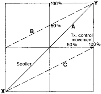
There is not much to adjust in this option. It is activated by the transmitter automatically when SPOILER or FLAP is assigned. You only need to tell the transmitter the position of the transmitter control for "spoilers retracted" – "back" or "forward".
As an example we will consider "09 CORTINA". Select this model, then, as in the previous examples, press M.
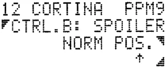
When leafing through the options at "SPOILER" the following display appears:
12 CORTINA PPM9 CTRL.B: SPOILER NORM POS.
Press the key; the arrow under "Normpos" starts to flash. You can reverse the facility with the R key, if necessary.
At "Arrow forward" you select "idle forward", and vice versa.
With the key you switch to Norm Pos "Centre", and if your transmitter control is at centre (a – sign will be visible in the display) you can switch over to one of the end-points with the + key. If necessary you can then change the end-point again by pressing R, and select whether Norm Pos is to affect forward movement (↑) or back movement (↓). The Norm-position is the source point for mixed functions.
That's it; leave the menu in the usual way with the M key.
One further point to note in this connection: If you wish to mix spoiler and elevator, or flap and elevator, you must assign the corresponding servo to "ELE+" instead of "ELE"! In this case the inputs Flap and Spoiler will be available in addition to elevator.
43
How to use the "Combi-Switch"
The main use of the Combi-Switch is to help the less experienced pilot handle the more demanding forms of model glider. For aerodynamic reasons many gliders require co-ordinated control of rudder and ailerons in order to fly a smooth turn - just like the full-size. However, simultaneous control of two functions can present problems, especially for the less practised pilot.
The Combi-Switch is used to couple these two controls electronically. The coupling can be be turned on and off via a switch, so that it is possible to switch between "normal" (separate controls) and coupled controls at any time in flight.
You can choose the way in which the coupling works: The rudder follows the ailerons; in this case you operate both controls with the aileron stick. The ailerons follow the rudder; in this case you operate both controls with the rudder stick. The mode which you choose is a matter of personal preference. In both cases you retain full control of the "following" (or "slave") function via its own stick.
A further point which needs explanation here is the "following rate". It can be set to any point between 0 and 200%.
An explanation: At a following rate of 50% the slave control surface will deflect to half its full travel when the master control is at full throw. The only way of getting greater movement from the following control surface is to operate its own stick. At a following rate of 100% both control surfaces move to the same extent.
At a following rate of 200% the slave control surface deflects to its full extent when the master control surface is only at half-throw. If the master stick is moved beyond this point, the master control surface moves to its full extent; the slave control surface stays at full throw – because there's no more movement available.
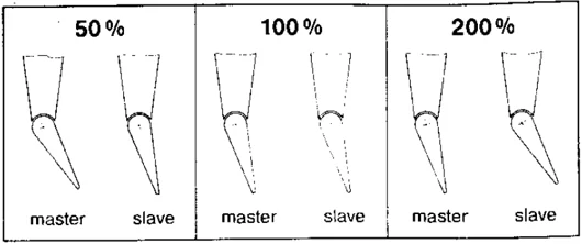
Fig. 28
It is very difficult for us to make recommendations here, as the ideal following rate varies from model to model. If in doubt, you could start with 100% and then carry out test flights to find the best setting for smooth, tidy turns.
This is an ideal case for using the Digi-Adjustor, as you can then easily adjust the following rate in flight.
Now, after this necessary preamble, to the matter in hand:
You cannot set up the Combi-Switch until you have already assigned one transmitter control to ailerons and one to rudder. You will also need to provide, or "release", a switch for the function. As supplied, the transmitter is set up to use switch S5; it is installed on the left, next to the display.
We will take as our example "06 FIESTA".
You will find the special Combi-Switch menu under "Transmitter Control Adjustment".
From the Status display you reach this menu with the key sequence M [square icon]. Then press [square icon] to go on. You will see this display:
02 FLAMINGO PPM7 COMBI-SW: S5↓ FOLLOWING: 100%↓ AILERON→ RUDDER
"S5↓" in the second line indicates that switch S5 is selected as the Combi-Switch. Press the [square icon] key, and "S5↓" flashes. Using the [+] and [-] keys you can now select a different switch. If you continue pressing the [-] key the final option that appears is "ON". Press y, and "ON" becomes "OFF". Now the Combi-Switch is out of circuit:
02 FLAMINGO PPM7 COMBI-SW: OFF FOLLOWING: 100%↓ AILERON→ RUDDER
44
As we don't want that at the moment, press Ⓡ again ("ON"), then the ⊕ key, until "55↓" appears again.
The ↓ arrow after "S5" indicates that the switch is on – i.e. the controls are coupled – if you move the switch in the direction of the arrow. If you wish to reverse this, press the Ⓡ key now; this reverses the direction of operation of the switch. In the display you will see that the ↓ arrow turns into a ↑ arrow.
Incidentally: when the switch is in the ON position, an asterisk appears after the arrow in confirmation (↑*).
Now you can select whether aileron is to be master and rudder the slave, or vice versa.
Press the ◩ key; the following rate value starts to flash. If you press the Ⓡ key, the bottom line of the display alternates between "RUDDER governs AILERON" and "AILERON governs RUDDER". Leave it as you want it to work. In our example we will leave it at "AILERON governs RUDDER", i.e. the aileron control is the master.
Now you have to set the value for the following rate: as the appropriate input field is already flashing, i.e. "released", simply set the value you want with the ⊕ or ⊖ keys, or the Digi-Adjustor; in our example 100%.
In the display you should see the following:
02 FLAMINGO PPM7 COMBI-SW: 55↓ ↘ FOLLOWING: 100%↓ AILERON+ RUDDER
That's all there is to it: you can leave the menu with the Ⓜ key.
If you want to adjust the following rate in flight: Before launching the model, move to the menu as described and press the ◩ key, to release the value input field. Don't leave the menu! While you are flying your model you can now vary the value of the following rate by rotating the Digi-Adjustor. Land the model and press the Ⓜ key to store the value you have found to be correct.
Caution!
Never attempt to make changes via the keypad while the model is flying. You would have to take your eyes off the model to find the right key; and if you made a mistake, the results could be catastrophic! For in-flight adjustments use the Digi-Adjustor, which you can operate "blind".
Memories and lists

When you were deciding which radio set to purchase, the fact that the PROFI mc 3030 transmitter can store, or memorise, up to 99 different models was undoubtedly an important factor. First a little information on the way in which the PROFI mc 3030 records and stores the model information. Then we will move on to the more practical matter of the "Memory" Menu and its sub-menus, which are used for: copying memories deleting memories switching memories naming memories checking and matching trim settings
The model list - a simple principle
Imagine one of your models. And now imagine all the aspects of that model for which the transmitter has to be adjusted (the technical term is "configured"). For example, the settings might be: Aileron on the right-hand stick; elevator left; exponential on elevator; differential ailerons, adjusted to a particular value; sweet bomb release, actuated by a switch, . . the normal position of the trim sliders; direction of servo rotation; . . As you occasionally fly this model at displays/events, a stopwatch would be a handy feature. . etc... If your transmitter had no "memory", you would probably write down all these points in a list and – when you change models – re-adjust the transmitter according to this list. You would write the name of the model at the top of the list.
The PROFI mc 3030 transmitter does exactly that. If you have already owned a transmitter with a memory, it is best to forget right now that it used "programs" and "adjustment values". These "programs" were nothing more exotic than lists of mixing arrangements, control characteristics etc., made up by the radio manufacturer; usually they could only be modified slightly, if at all. You might have liked a flap – elevator mixer instead of the V-tail mixer – but that was only available in another "program"... The PROFImc 3030 is quite honest about the matter of "programs". For each model your transmitter draws up a "list". It includes everything that applies to that particular model. You do not need to specifically create this list: when you set up the transmitter to meet your requirements, the transmitter assembles the list automatically: everything that you select or adjust is "noted down" by the transmitter. Thus you do not need to store the list in a separate procedure; if you switch off, then on again, the list you last used is "there again" immediately. You might object at this point: "that's all very well, but now I always have to make up this list before I can fly a new model, i.e. scratch around for the different assignments, mixers etc. That sounds complicated, and other manufacturers offer ready-made programs!" We have two answers to this: 1.) You will soon see that the procedure is by no means complicated or difficult. For your slight effort, however, your reward is that you can seek out and assemble precisely those options and features that you want, "a la carte". And you can leave out what you don't need. 2.) In any case, if the idea of so much "work" is off-putting, or you do not trust your ability at first, the transmitter includes 10 ready-made lists as standard, which cater for the vast majority of models. Some other manufacturers would call this provision "10 programs". How many lists are available? The transmitter can store 15 or 99 such lists, and recall any one of them at any time, when you want to change models. This is probably the most frequently used "memory operation", and it could hardly be easier. When you want to "call up" a different list, move to the "Memory" menu, select "SHIFT", then "leaf through" to the model you want to fly (model names in English – no codes!), and that's (almost) all there is to it. See page 50 for more details of this procedure. But there are other "memory operations". For example, you can create a copy of a tried and tested list, and you can then give the copy a new name. You can "clear the decks" and erase lists which you no longer need; and much more. We don't mind if you want to use the ordinary terms. We have used the word "list" here, because that is what the transmitter actually assembles for each model, and because a list is easier to imagine than a "program". Now, it has become usual to talk of "storing models" or "copying memories". In fact it would be pretty difficult to store even one model in a transmitter – it just ain't big enough. Copying the memory chips in the transmitter is not exactly a simple job, either.
46