ACS 600 MultiDrive
This manual includes • Safety • Installation • Commissioning of the Drive Section • Maintenance
Hardware Manual
ACA 6xx Frequency Converters 3 to 4300 kW
ABB

ACS 600 MultiDrive Manuals (Air-cooled Units, English Originals)
GENERAL MANUALS
*Safety and Product Information EN 63982229
- Complete general Safety Instructions
- Technical data for DSU and TSU supplies and Drive Sections: ratings, power losses, dimensions, weights, fuses etc.
*System Description EN 63700151
- General description of ACS 600 MultiDrive
*Hardware Manual EN 63700118
- General Safety Instructions
- Hardware description of the Drive Section
- Cable selection
- ACS 600 MultiDrive mechanical and electrical installation
- Hardware commissioning of the Drive Section
- Preventive maintenance of ACS 600 MultiDrive
ACS 600 MultiDrive Control Electronics LED Indicators EN 64289721
- LED descriptions
**Modules Product Catalogue EN 64104268
- Supply Unit components
- Drive Unit components
- Dynamic Braking Units
- DriveWare information
- Dimensional drawings
- Single line diagrams
- Auxiliary power consumption
- Master component tables
**Modules Installation Manual EN 64119010
- Cabinet assembly
- Wiring
**Grounding and Cabling of the Drive System EN 61201998
- Grounding and cabling principles of a variable speed drive system
**EMC Compliant Installation and Configuration for a Power Drive System EN 61348280
- Included with cabinet-assembled systems only ** Included in Modules deliveries only
SUPPLY SECTION MANUALS (depending on the supply type one of these manuals is included in the delivery)
Diode Supply Section (DSU) EN 61451544
- DSU specific Safety Instructions
- DSU hardware and software descriptions
- DSU commissioning
- Earth fault protection options
Thyristor Supply Section (TSU) EN 64170597
- TSU operation basics
- TSU firmware description
- TSU program parameters
- TSU commissioning
IGBT Supply Section (ISU) EN 64013700
- ISU specific Safety Instructions
- Main components of ISU
- ISU ratings
- ISU power losses
- ISU dimensions and weights
- ISU fuses
- ISU program parameters
- Earth fault protection options
FIRMWARE MANUALS FOR DRIVE APPLICATION PROGRAMS (appropriate manual is included in the delivery)
System EN 63700177
- Commissioning of the System Application Program
- Control Panel use
- Software description
- Parameters of the System Application Program
- Fault tracing
- Terms
Application Program Template EN 63700185
- Commissioning of the Drive Section
- Control Panel use
- Software description
- Parameters
- Fault tracing
- Terms
Standard EN 61201441
- Control Panel use
- Standard application macros with external control connection diagrams
- Parameters of the Standard Application Program
- Fault tracing
- Fieldbus control Note: a separate Start-up Guide is attached
Crane Drive EN 3BSE 011179
- Commissioning of the Crane Drive Application Program
- Control Panel use
- Crane program description
- Parameters of the Crane Drive Application Program
- Fault tracing
CONTROL SECTION MANUALS (delivered with optional Control Section)
Advant Controller 80 User’s Manual EN 64116487
- AC 80 hardware and connections
- AC 80 software
- Programming
- Diagnostics
Advant Controller 80 Reference Manual PC Elements EN 64021737
- Description of PC and DB elements
Advant Controller 80 Reference Manual TC Elements EN 64331868
- Description of TC elements
BRAKING SECTION MANUAL (delivered with optional Braking Section)
ACA 621/622 Braking Sections User’s Manual EN 64243811
- Installation, Start-up, Fault tracing, Technical data
- Dimensional drawings
MANUALS FOR OPTIONAL EQUIPMENT (delivered with optional equipment)
Fieldbus Adapters, I/O Extension Modules, Braking Choppers etc.
- Installation
- Programming
- Fault tracing
- Technical data
ACA 6xx Frequency Converters
3 to 4300 kW
Hardware Manual
This manual concerns ACS 600 MultiDrive frequency converters equipped with an ACA 631/633 Diode Supply Section, an ACA 632/634/636/637/638/639 4Q Thyristor Supply Section or an ACA 635 IGBT Supply Section, and with the ACA 610 Drive Sections.
Chapters 2 and 3 also apply to ACS/ACC 607, ACS/ACC 627 and ACS/ACC 677 frequency converter types -0760-6, -0930-5, -0900-6 or above (from 630 to 3000 kW). In the text, they are collectively referred to as ACx 6x7. The parts applicable to ACx 6x7 only are marked ACx 6x7.
3AFY 63700118 R0125 REV E EN EFFECTIVE: 2.5.2001 SUPERSEDES: 7.2.2000
© 2001 ABB Industry Oy. All Rights Reserved.
This page is blank.
Safety Instructions
Overview
The complete safety instructions stated for ACS 600 MultiDrive in Safety and Product Information must be followed when installing, operating and servicing the frequency converters. Study the complete safety instructions carefully.
General Safety Instructions
These general safety instructions include only main parts of the complete safety instructions. The general safety instructions are intended for all work on the ACS 600 MultiDrive (referred to as ACx 600 in the text below). Neglecting these instructions may cause physical injury or death.

WARNING! All electrical installation and maintenance work on the ACx 600 should be carried out by qualified electricians.
Any installation work must be done with power off, and power is not to be reconnected unless the installation work is complete. Dangerous residual voltages remain in capacitors when the disconnecting device is opened. Wait 5 minutes after switching off the supply before starting work. Always ensure by measuring that the voltage between terminals UDC+ and UDC- and frame is close to 0 V and that the supply has been switched off before performing any work on the equipment or making main circuit connections.
If the main circuit of the inverter unit is live, the motor terminals are also live even if the motor is not running!
Open switch fuses of all parallel connected inverters before installation or maintenance work in any of them.
Check the cable connections at the shipping split joints before switching on the supply voltage.
If the auxiliary voltage circuit of the ACx 600 is powered from an external power supply, opening the disconnecting device does not remove all voltages. Control voltages of 115/230 VAC may be present on the digital inputs or outputs even though the inverter unit is not powered. Before starting work, check which circuits remain live after opening of the disconnecting device by referring to the circuit diagrams for your particular delivery. Ensure by measuring that the part of the cabinet you are working on is not live.
ACS 600 MultiDrive iii
Safety Instructions
In ACx 600 frequency converters, control boards of the converter unit may be at the main circuit potential. Dangerous voltages may be present between the control boards and the frame of the converter unit, when the main circuit voltage is on. It is critical that the measuring instruments, such as an oscilloscope, are used with caution and safety always as a priority. The fault tracing instructions give special mention of cases in which measurements may be performed on the control boards, also indicating the measuring method to be used.
Live parts on the inside of doors are protected against direct contact. Special safety attention shall be paid when handling shrouds made of sheet metal.
Do not make any voltage withstand tests on any part of the unit while the unit is connected. Disconnect motor cables before making any measurements on motors or motor cables.
WARNING! Close switch fuses of all parallel connected inverters before starting the frequency converter.
Do not open the drive section switch fuses when the inverter is running.
Do not use Prevention of Unexpected Start for stopping the drive when the inverter is running. Give a Stop command instead.
CAUTION! Fans may continue to rotate for a while after the disconnection of the electrical supply.
CAUTION! Some parts like heatsinks of power semiconductors and toroidal cores on motor cables inside of cabinet remain hot for a while after the disconnection of the electrical supply.
iv ACS 600 MultiDrive
Safety Instructions
Starting TSU or DSU Note the warning below before starting drives equipped with a Thyristor or Diode Supply Section.
⚠️ WARNING! Before power switch-on, make sure that a sufficient inverter power is connected to the intermediate circuit. Rules of thumb:
- The sum power of the inverters connected must be at least 30% of the sum power of all inverters.
- The sum power of the inverters connected must be at least 30% of the rated power of the braking section ($P_{br.max}$) if present.
If the above mentioned rules are not followed, the DC fuses of the connected inverter(s) may blow or the braking chopper (if used) may be damaged.
The phenomena which result in a fuse blow are as follows:
- At start, a charging current high enough for charging all the inverters flows to the connected ones.
- In Thyristor Supply Sections, the DC voltage may overshoot the controller bridge change limit, causing an immediate change to regeneration and a high reverse current.
- The DC voltage may overshoot the braking chopper controller voltage limit, causing an immediate switching into braking mode and a high braking current, which in turn discharges low power inverter capacitors.
The braking chopper may be damaged by repeated on-off switching of the braking due to a high supply and braking section power compared to the inverter power.
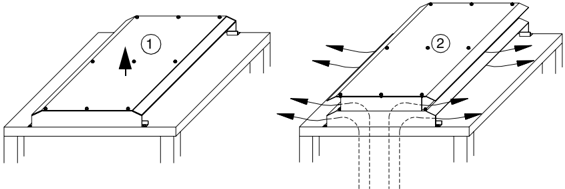
Double Roof If the drive is equipped with a double roof, ensure that the roof is lifted up from the transportation position to enable the cooling air flow before starting the drive.

ACS 600 MultiDrive v
Safety Instructions
vi
ACS 600 MultiDrive
Table of Contents
ACS 600 MultiDrive Manuals (Air-cooled Units, English Originals)
Safety Instructions
- Overview . . . . . . . . . . . . . . . . . . . . . . . . . . . . . . . . . . . . . . . . . . . . . . . . . . . . . . . . . . . . . . . . . . . . . . . . . . . . . . . . . . . . . . . . . . . . . . . . . . . . . . . . . . . . . . . . . . . . . . . . . . . . . . . . . . . . . . . . . . . . . . . . . . . . . . . . . . . . . . . . . . . . . . . . . . . . . . . . . . . . . . . . . . . . . . ........ iii
- General Safety Instructions . . . . . . . . . . . . . . . . . . . . . . . . . . . . . . . . . . . . . . . . . . . . . . . . . . . . . . . . . . . . . . . . . . . . . . . . . . . . . . . . . . . . . . . . . . . . . . . . . . . . . . . . . . . . . . . ........ iii
- Starting TSU or DSU . . . . . . . . . . . . . . . . . . . . . . . . . . . . . . . . . . . . . . . . . . . . . . . . . . . . . . . . . . . . . . . . . . . . . . . . . . . . . . . . . . . . . . . . . . . . . . . . . . . . . . . . . . . . . . . . . . ........
- Fastening the Shipping Split to the Floor . . . . . . . . . . . . . . . . . . . . . . . . . . . . . . . . . . . . . . . . . . . . . . . . . . . . . . . . . . . . . . . . . . . . . . . . . . . . . . . . . . . . . . . . . . . . . . . . . . . . . . . . ........ 2-7
- Fastening Clamps. . . . . . . . . . . . . . . . . . . . . . . . . . . . . . . . . . . . . . . . . . . . . . . . . . . . . . . . . . . . . . . . . . . . . . . . . . . . . . . . . . . . . . . . . . . . . . . . . . . . . . . . . . . . . . . . . . . . ........ 2-7
- Holes inside the Cabinet. . . . . . . . . . . . . . . . . . . . . . . . . . . . . . . . . . . . . . . . . . . . . . . . . . . . . . . . . . . . . . . . . . . . . . . . . . . . . . . . . . . . . . . . . . . . . . . . . . . . . . . . . . . . . . . . ........
- NIOC Board Chaining . . . . . . . . . . . . . . . . . . . . . . . . . . . . . . . . . . . . . . . . . . . . . . . . . . . . . . . . . . . . . . . . . . . . . . . . . . . . . . . . . . . . . . . . . . . . . . . . . . . . . . . . . . . . . . . . . . . ........ 3-33
- CDP 312 and NLMD-01 (ACS 600 MultiDrive) . . . . . . . . . . . . . . . . . . . . . . . . . . . . . . . . . . . . . . . . . . . . . . . . . . . . . . . . . . . . . . . . . . . . . . . . . . . . . . . . . . . . . . . . . . . . . . . . . . . . . . . ........ 3-34
- RS-485 Termination Settings . . . . . . . . . . . . . . . . . . . . . . . . . . . . . . . . . . . . . . . . . . . . . . . . . . . . . . . . . . . . . . . . . . . . . . . . . . . . . . . . . . . . . . . . . . . . . . . . . . . . . . . . . . . . ........
x
ACS 600 MultiDrive Hardware Manual
Chapter 1 – Introduction
Overview of the Manual
Study this manual carefully before installing, commissioning, operating or servicing the frequency converter. We expect that you have a basic knowledge of physical and electrical fundamentals, electrical wiring practices, electrical components and electrical schematic symbols.
ACS 600 MultiDrive frequency converters consist of a Supply Section and one or several Drive Sections. This manual covers:
- System and hardware descriptions of the Drive Section.
- Mechanical and electrical installation of the Supply Section and the Drive Section. Details are given such as: moving of the shipping sections, joining of the shipping sections together, joining of the busbars and fastening of the cabinets to the floor.
- Commissioning of the Drive Section. Note: For Supply Section commissioning, parameters, fault tracing and product information see Supply Sections User’s Manual (DSU, TSU or IGBT).
- Preventative maintenance. Note: Fault and warning messages given by the software are described in ACS 600 Firmware Manual (for System, Standard or Crane Drive Application Program) or in Supply Sections User’s Manual (DSU, TSU or IGBT).
Other Manuals
The guide Safety and Product Information (English code: 63982229) includes for ACS 600 MultiDrive:
- The Complete Safety Instructions (see also the user’s manual for the supply section).
- The Technical Data (see also the user’s manual for the supply section). Information concerning ratings, fuses, cooling requirements, power losses, dimensions etc. is given.
The use of the Control Panel and parameter setting of the inverter application program is described in ACS 600 Firmware Manual (for System, Standard or Crane Drive Application Program).
For optional equipment, refer to the accompanying manuals.
For additional information about the drive system, refer to Grounding and cabling of the drive system (EN code: 61201998).
Chapter 1 – Introduction
Inquiries Any inquiries about the product should be addressed to the local ABB representative, quoting the type code and serial number of the unit. If the local ABB representative cannot be contacted, inquiries should be addressed to ABB Industry, Helsinki, Finland.
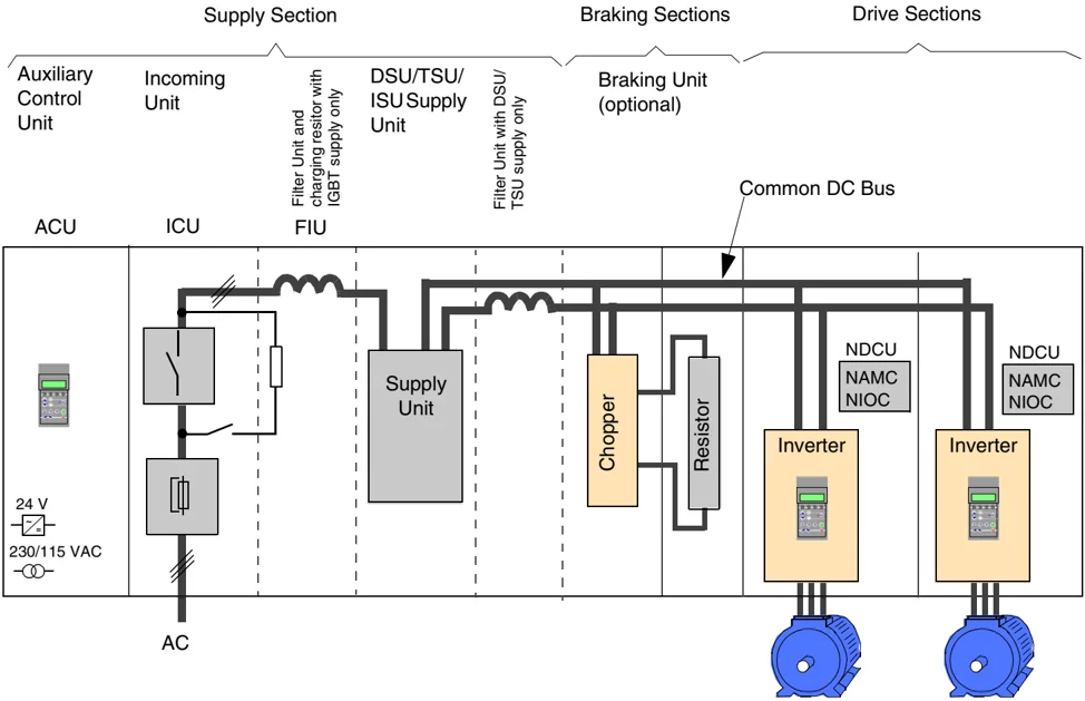
The Main Components of the Drive The main components of an ACS 600 MultiDrive frequency converter (AC Drive) are shown below. The Supply Unit is equipped with either a Diode, a Thyristor or an insulated gate bipolar transistor (IGBT) input bridge. The Filter Unit is included in IGBT Supply Units only. Two drive sections are drawn in the diagram, even though the number of them varies. The Braking Unit is an option. For a more detailed description of the Supply Unit refer to the Supply Sections User’s Manuals. This chapter describes the Drive Section in more detail.
ACS 600 MultiDrive Hardware Manual
Chapter 1 – Introduction
Drive Section The drive section consists of the parts listed below:
- One to three Drive Units
- Output cubicle (with parallel connected inverter units and units with motor cable entry and exit through the top of the cabinet)
- DC Fuses or a disconnecting switch (Switch Fuse with Charging Circuitry)
- Cabinet mechanics
- CDP 31x Control Panel (optional)
- NLMD-01 Monitoring Display (optional).
Example A block diagram of a 2 x R11i drive section is shown below.
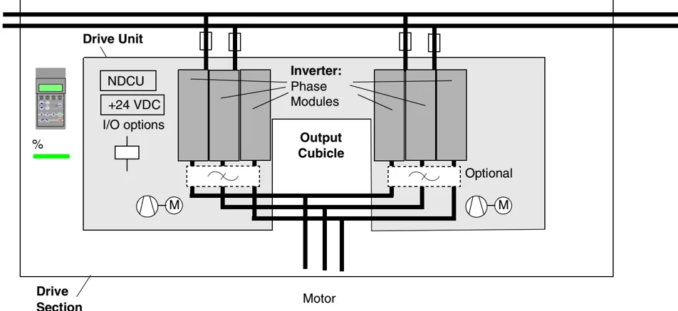
Drive Unit The drive unit includes the parts listed below:
- Inverter
- External Inverter Unit Cooling Fans (frames R6i to 4 x R12i only)
- Drive Control Units (NDCU), which include an Application and Motor Controller (NAMC) Board and a standard I/O (NIOC) Board
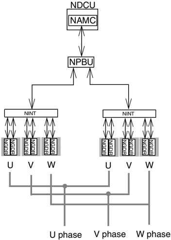
- Optical Branching Unit (NPBU) with parallel connected units
- Control wiring and relays (for e.g. optional prevention of unexpected start)
- du/dt Filters (optional)
ACS 600 MultiDrive Hardware Manual
Chapter 1 – Introduction
- Optional modules (I/O extension and fieldbus adapter modules, pulse encoder interface module etc.)
- Other options.
Inverter
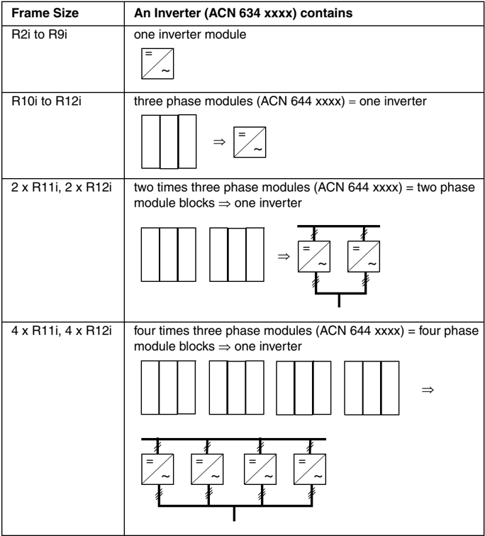
The inverter contains an IGBT output bridge which forms controlled a.c. voltage from the intermediate circuit d.c. voltage. An inverter controls one motor.
| Frame Size | An Inverter (ACN 634 xxxx) contains |
|---|---|
| R2i to R9i | one inverter module |
| R10i to R12i | three phase modules (ACN 644 xxxx) = one inverter |
| 2 x R11i, 2 x R12i | two times three phase modules (ACN 644 xxxx) = two phase module blocks \Rightarrow one inverter |
| 4 x R11i, 4 x R12i | four times three phase modules (ACN 644 xxxx) = four phase module blocks \Rightarrow one inverter |
1-4 ACS 600 MultiDrive Hardware Manual
Chapter 1 – Introduction
Control Boards One phase module block includes the following boards:
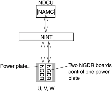
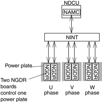
- main circuit interface board (NINT): This board gives the control commands and sends measurement signals.
- two control distribution boards (NXPP, in frame size R10i and up). These boards distribute the control commands given by the NINT board.
- gate driver boards (NGDR), in frame size R4i and up. These boards amplify the control pulses for the insulated gate bipolar transistors (IGBTs).
- power supply board for gate drivers (NGPS) in V-phase module
- power supply board (NPOW-62) in V-phase module. This board is not included in frame sizes R2i and R3i.
- main circuit board NBUB in frame size R3i
An inverter of frame size 2 x R12i includes twice the control boards of an R12i inverter. An inverter of frame size 3 x R12i includes three times the control boards of an R12i inverter, etc.
Control Board Diagram (R4i to R7i) This diagram shows the control boards that control an inverter of size R4i to R7i.
ACS 600 MultiDrive Hardware Manual
Chapter 1 – Introduction
Control Board Diagram (R8i, R9i) This diagram shows the control boards that control an inverter of size R8i/R9i.
Control Board Diagram (2 x R8i, 2 x R9i) This diagram shows the control boards that control an inverter of sizes 2 x R8i and 2 x R9i.
1-6 ACS 600 MultiDrive Hardware Manual
Chapter 1 – Introduction
Control Board Diagram (R10i, R11i) This diagram shows the control boards that control an inverter of sizes R10i and R11i.
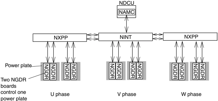
NDCU NAMC
NXPP NINT NXPP
Power plate Two NGDR boards control one power plate
NGDR NGDR NGDR NGDR NGDR NGDR NGDR NGDR NGDR NGDR NGDR NGDR
U phase V phase W phase
Control Board Diagram (R12i) This diagram shows the control boards that control an inverter of size R12i.
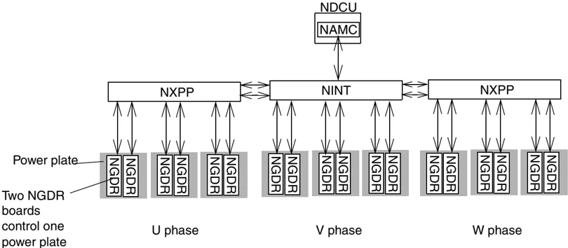
NDCU NAMC
NXPP NINT NXPP
Power plate Two NGDR boards control one power plate
NGDR NGDR NGDR NGDR NGDR NGDR NGDR NGDR NGDR NGDR NGDR NGDR NGDR NGDR NGDR NGDR
U phase V phase W phase
ACS 600 MultiDrive Hardware Manual 1-7