Chapter 1 – Introduction
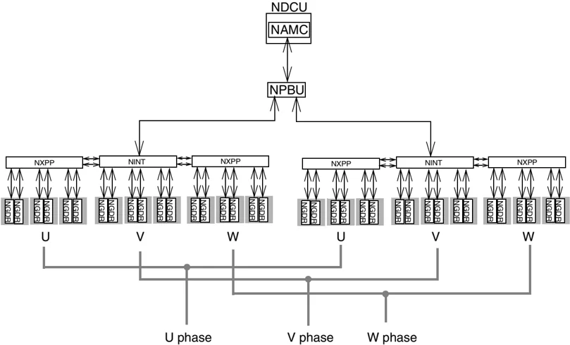
Control Board Diagram (2 x R12i) This diagram shows the control boards that control an inverter of size 2 x R12i.
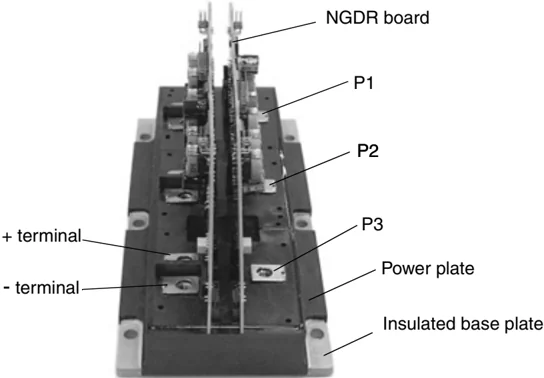
Power Plate This photo shows one power plate with the NGDR boards connected.
1-8 ACS 600 MultiDrive Hardware Manual
Chapter 1 – Introduction
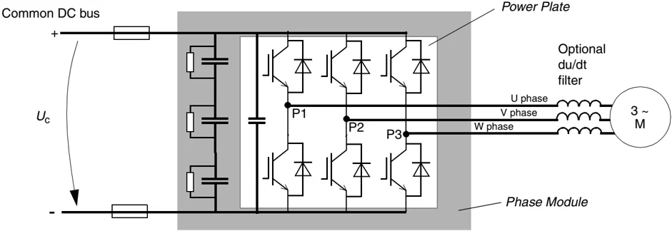
Main Circuit Diagram
Frame Size R8i/R9i Frame R8i/R9i contains three phase modules, each producing one of the three phases driving the motor.
ACS 600 MultiDrive Hardware Manual
Chapter 1 – Introduction
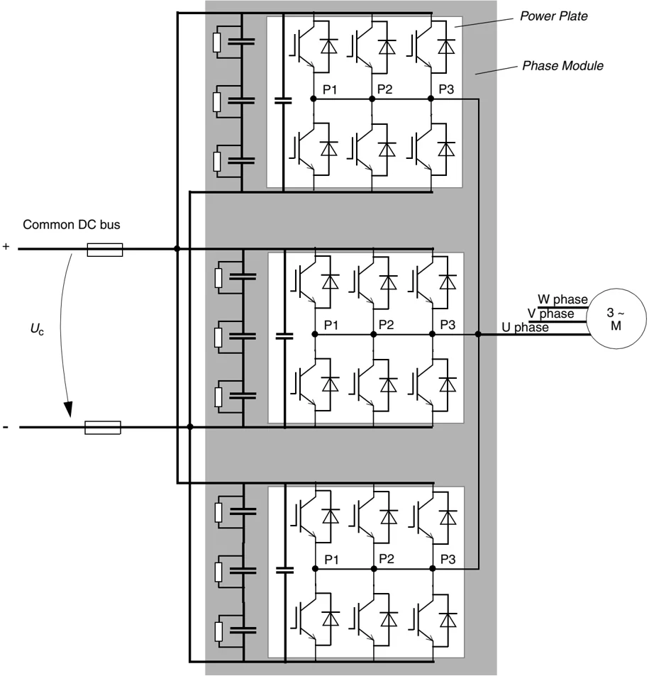
Frame Size R12i Frame R12i contains three phase modules, each producing one of the three phases driving the motor. Each phase module consists of three parallel connected power plates. Six IGBTs with free wheeling diodes are integrated to a single power plate. The figure below shows the connection of one phase.
Chapter 1 – Introduction
Voltages from the Supply Section The supply section supplies the inverter via the DC bus. The inverter also takes energy from the DC busbars to make control voltages for the control boards and auxiliary voltage for I/O board.
Voltage for inverter cooling fans for frame sizes R2i to R5i is taken from the DC busbar. For larger frame sizes the cooling fan voltage is taken from the 230/115 V a.c. transformer (in the Auxiliary Control Unit) via thermal protection switch F10, F11 or F12 (depending on the frame size).
The 24 V auxiliary voltage source is powered from a 230/115 V a.c. transformer (in ACU) via F31 (or for frame sizes R7i and smaller via F10).
The emergency stop and the optional uninterrupted power supply (UPS) are wired from the Auxiliary Control Unit.
Drive Section Configurations Drive section configurations are described below.
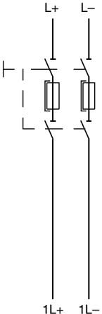
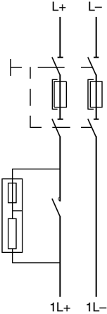
Drive Section Fuses The drive section is equipped with DC fuses or a switch fuse with charging circuitry (see below).
DC Fuses
 L+ L-
1L+ 1L-
ACS 600 MultiDrive Hardware Manual
Chapter 1 – Introduction
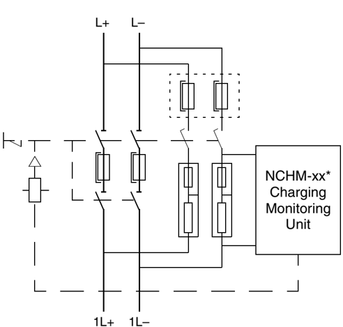
Switch Fuse with Charging Circuitry (Optional) The capacitors of the intermediate d.c. link (common DC bus) are charged via resistors to limit the charging current. In Type 1 the charging circuitry is implemented internally in the inverter unit (frames R2i to R4i). In Type 2 the charging is monitored internally (frames R5i and R6i). In Type 3 the charging circuitry and monitoring are implemented with external components (frames R7i to R12i). In drive sections with parallel connected inverter units, each unit has its own switch fuse with a charging circuit.
Type 1
Type 2
Type 3
- NCHM-11 is used with 115 V AC and NCHM-21 with 230 V AC auxiliary voltage
1-12 ACS 600 MultiDrive Hardware Manual
Chapter 1 – Introduction
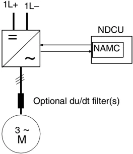
Single Inverter Modules One NAMC board controls the inverter unit. It is located on the DIN rail at the left side of the inverter unit cabinet inside the Drive Control Unit (NDCU) box together with the NIOC board.
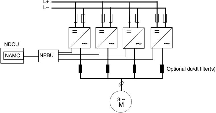
Parallel Connected Phase Module Blocks One NAMC board controls all parallel connected phase module blocks via an optical branching unit (NPBU-4x) which forwards commands simultaneously to the interface (NINT) boards of the blocks. Each block is supplied via fuses.
ACS 600 MultiDrive Hardware Manual
Chapter 1 – Introduction
1-14 ACS 600 MultiDrive Hardware Manual
Chapter 2 – Mechanical Installation
General This chapter provides instructions for moving the shipping splits, fastening them to the floor and joining them together. These instructions apply to the ACS 600 MultiDrive (ACA 6xx) and the ACx 6x7 (132 to 3000 kW). Instructions concerning only some types are marked.
See Safety and Product Information (ACS 600 MultiDrive, EN code 63982229) or Appendix A (ACx 6x7) for allowed operating conditions of the frequency converter and sufficient room around the unit. Room around the unit is required to enable cooling air flow, service and maintenance. Proper mechanical installation is an important element for a trouble-free installation and should be followed closely.
The frequency converter cabinets should be installed in an upright vertical position.
The floor that the unit is installed on should be of non-flammable material, as smooth as possible, and strong enough to support the weight of the unit. The floor flatness must be checked with a spirit level before the installation of the cabinets into their final position. The maximum allowed deviation from the surface level must be ≤ 5 mm measured every 3 m. The installation site should be levelled, if necessary, as the cabinet is not equipped with adjustable feet.
The wall behind the unit should be of non-flammable material.
Required Tools The tools required for moving the shipping splits to their final location, fixing them to the floor and tightening the connections are listed below.
- Iron bar and roller tubes or similar for moving a shipping split
- Pozidrive and Torx (2.5–6 mm) screwdrivers for the tightening of the frame screws
- Torque wrench
- A 19 mm wrench set for tightening the DC horizontal busbars between shipping splits
- A 17 mm wrench set for tightening the PE busbars between shipping splits
ACA 6xx Sections and ACS/ACC 6x7 (132 to 3000 kW) Frequency Converters 2-1
Chapter 2 – Mechanical Installation
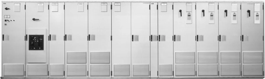
Cabinet Construction The air-cooled ACS 600 MultiDrive and the ACx 6x7A use the same cabinet construction. In marine versions, the cabinet includes, in addition, vibration dampers and handles on the doors.
ACS 600 MultiDrive and ACx 6x7
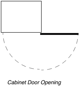
Cabinet Door Opening
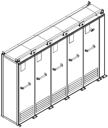
Marine Applications (ACS 600 MarineDrive)
2-2 ACA 6xx Sections and ACS/ACC 6x7 (132 to 3000 kW) Frequency Converters
Chapter 2 – Mechanical Installation
Moving of the Shipping Split
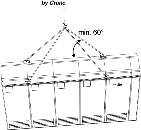
by Crane
min. 60°
Use the steel lifting lugs attached to the top of the cabinets. Insert the lifting ropes or slings into the holes of the lifting lugs.
The lifting lugs can be removed (not mandatory) once the cabinets are in their final location. If the lifting lug is removed, the bolts for each lug must be refastened to maintain the degree of protection of the cabinet.
ACx 6x7: IP 54
Allowed minimum height of lifting ropes or slings for IP 54 shipping splits is 2 metres.

ACA 6xx Sections and ACS/ACC 6x7 (132 to 3000 kW) Frequency Converters
Chapter 2 – Mechanical Installation
by Fork-lift
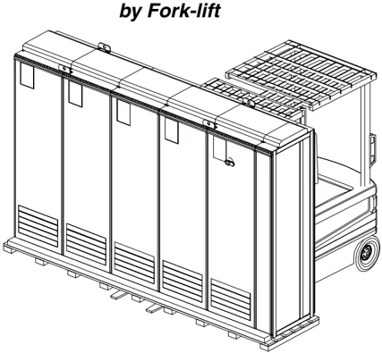
The centre of gravity may be quite high. Be therefore careful when transporting the shipping splits. Tilting of the cabinets must be avoided. Moving of the shipping split is to be done only with the cabinets upright.
by Split Rollers (Not allowed in marine versions)
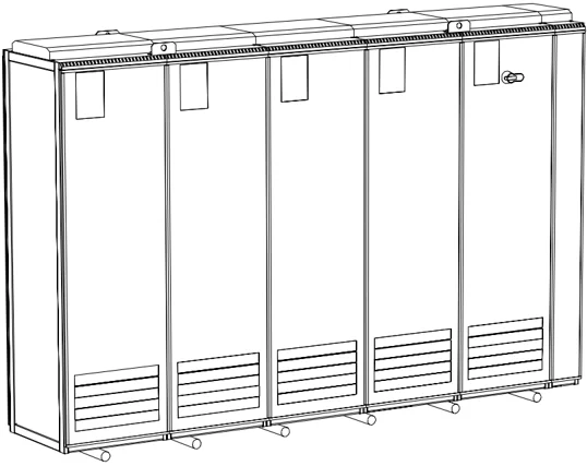
Remove the bottom wooden frame which is part of the shipment. Lay the shipping split on the rollers and move the unit carefully until it is close to its final location. Remove the rollers by lifting the shipping split using a crane or fork-lift truck as described above.
2-4 ACA 6xx Sections and ACS/ACC 6x7 (132 to 3000 kW) Frequency Converters
Chapter 2 – Mechanical Installation
Final Placement of the Shipping Splits (Not allowed in marine versions)
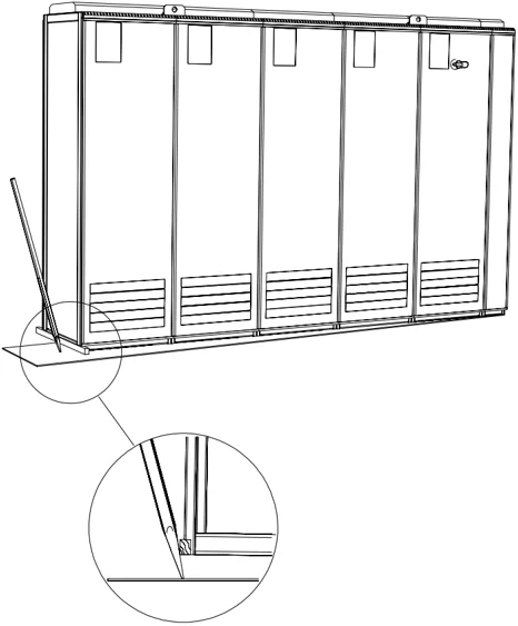
The cabinets can be moved into their final position by using an iron bar and a wooden piece at the bottom edge of the cabinet. Care is to be taken to properly place the wooden piece so as not to damage the cabinet frame.
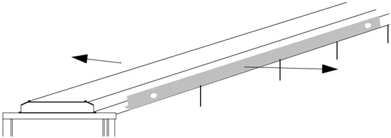
Removing the Lifting Lugs and Bars
Remove the lifting bars (if used) after lifting, as they disturb the cooling of the unit. Remove the lifting lug of marine versions. Refasten the original bolts or fasten the upper vibration dampers (if used) in order to maintain the degree of protection of the cabinet.
ACA 6xx Sections and ACS/ACC 6x7 (132 to 3000 kW) Frequency Converters
Chapter 2 – Mechanical Installation
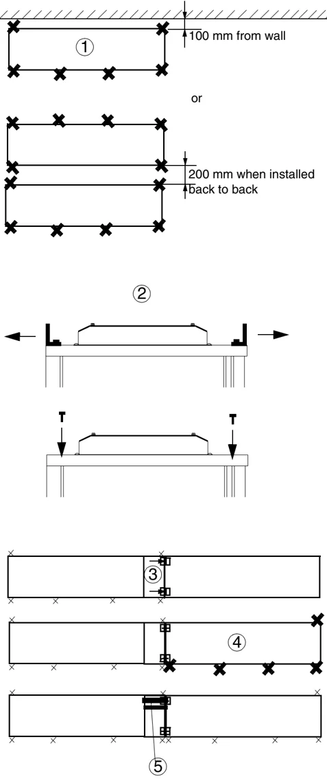
Working Order of the Mechanical Installation
-
Fasten the first shipping split to the floor with fastening clamps or through the holes inside the cabinet. See section Fastening the Shipping Split to the Floor. In marine versions, fasten the first shipping split to the floor and roof/wall as described in section Vibration Dampers on Top and Bottom (Marine Versions). Note: Any height adjustment of the cabinets must be done before fastening the cabinets together. Height adjustment can be done by using metal shims between the bottom frame and floor.
-
Remove the lifting bars (if used) and the lifting lugs in marine applications. Place the original bolts or upper vibration dampers to the holes.
-
Fasten the first shipping split to the next shipping split. Each shipping split includes a 200/600 mm joining cabinet.
-
Fasten the second shipping split to the floor.
-
Connect the DC busbars and the PE busbar.
-
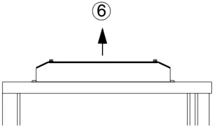
Lift the upper part of the cabinet roof up (if a double roof).
2-6 ACA 6xx Sections and ACS/ACC 6x7 (132 to 3000 kW) Frequency Converters
Chapter 2 – Mechanical Installation
Fastening the Shipping Split to the Floor
Fastening the shipping split to the floor is especially important in installations subjected to vibration or other movement.
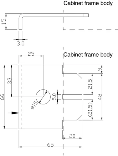
Fastening Clamps Insert the clamp into the longitudinal hole in the edge of the cabinet frame body and fasten it with a bolt to the floor. Allowed maximum distance between the fastening clamps is 800 mm.
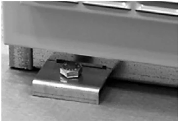
Fastening hole distances for the common cabinet are given below. Fastening bolt: M10 to M12 (3/8" to 1/2").
\begin{tabular}{|l|l|} \hline Cubicle Width & Hole Distance (mm) \ \hline & \ \hline 200 & \ \hline 400 & a: 250 \ \hline 600 & a: 450 \ \hline 800 & a: 650 \ \hline 1000 & a: 350, b: 150, a: 350 \ \hline 1500 & a: 350, b: 150, a: 350, b: 150, a: 350 \ \hline \end{tabular}
Dimensions of the fastening clamp
ACA 6xx Sections and ACS/ACC 6x7 (132 to 3000 kW) Frequency Converters 2-7
Chapter 2 – Mechanical Installation
Holes inside the Cabinet The cabinet can be fastened to the floor using the fastening holes inside the cabinet, if they are available and accessible. Allowed maximum distance between the fastening points is 800 mm.
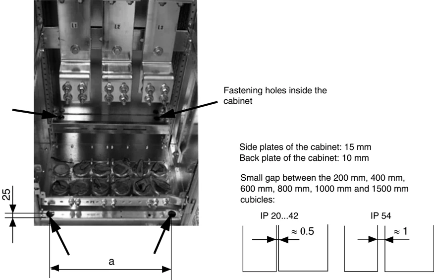
Fastening hole distances for the common cabinet are given below. Fastening bolt: M10 to M12 (3/8" to 1/2").