Chapter 3 – Electrical Installation
2 x R11i/R12i without Common Motor Connection Terminal
Motor cable connections with parallel symmetrical cables for two phase module blocks with a common motor are represented below. Note: With two parallel phase module blocks, the number of cables must be n x 2, where n = 1, 2, 3... With four parallel blocks the number of cables must be n x 4, where n = 1, 2, 3... Otherwise the output cabling must be done from a separate output cubicle.
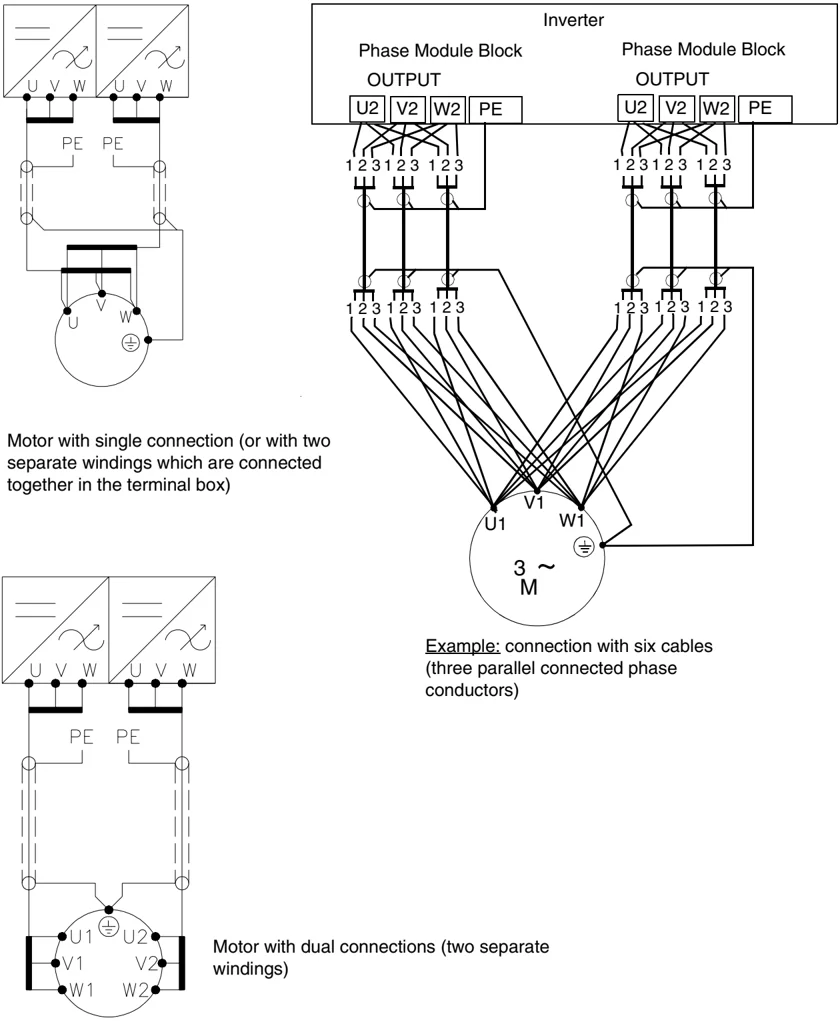
Motor with single connection (or with two separate windings which are connected together in the terminal box)
Example: connection with six cables (three parallel connected phase conductors)
Motor with dual connections (two separate windings)
ACA 6xx Sections and ACS/ACC 6x7 (132 to 3000 kW) Frequency Converters 3-15
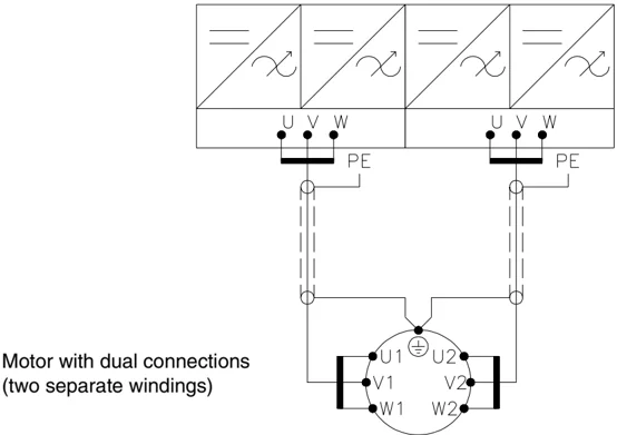
Inverters with Common Motor Connection Terminal Motor cable connections for parallel connected inverters with a common output cubicle(s) are presented below.
2 x R11i/R12i
 Motor with single connection (or with two separate windings which are connected together in the terminal box)
4 x R11i/R12i
 Motor with dual connections (two separate windings)
ACA 6xx Sections and ACS/ACC 6x7 (132 to 3000 kW) Frequency Converters
4 x R11i/R12i without Common Motor Connection Terminal Motor cable connections for four parallel connected inverters without a common output cubicle are presented below.
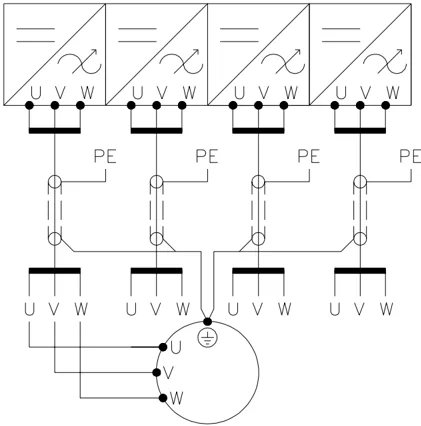
Motor with single connection (or with two separate windings which are connected together in the terminal box)
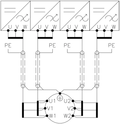
Motor with dual connections (two separate windings)
ACA 6xx Sections and ACS/ACC 6x7 (132 to 3000 kW) Frequency Converters
Inverter Modules of Frame Sizes R2i to R5i (ACS 600 MulitDrive)
The cable connections of a bottom entry unit are represented below. For top exit, an extra cabinet is required. .
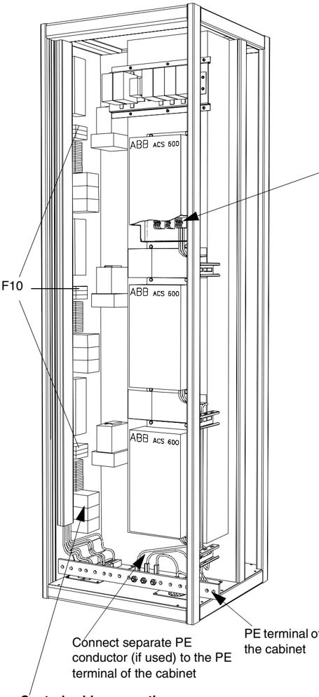
F10
ABB ACS 600 ABB ACS 600 ABB ACS 600
Connect separate PE conductor (if used) to the PE terminal of the cabinet
Control cable connection: Connect the control cables to the appropriate terminal block on the DIN rail.
PE terminal of the cabinet
Motor cable connection
- Strip the cable for 3 cm at the cabinet entry if EMC sleeves are used.
- Lead the cable unstripped to the inverter module.
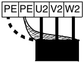
If connection terminals are outside the module, make the connections like this:
PE PE U2 V2 W2
Tighten the screw to the torque given in ACS 600 MultiDrive Safety and Product Information, Appendix A.
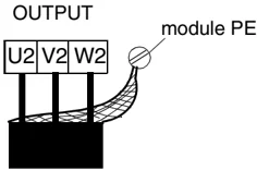
If connection terminals are inside the module,
- remove the module cover.
- make the connections:
OUTPUT U2 V2 W2 module PE
Tighten the screw to the torque given in ACS 600 MultiDrive Safety and Product Information, Appendix A.
3-18 ACA 6xx Sections and ACS/ACC 6x7 (132 to 3000 kW) Frequency Converters
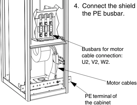
Inverter Modules R6i and R7i (ACS 600 MultiDrive) The cable connections of a bottom entry unit are represented below. For top exit, an extra cabinet is required (200 mm to 800 mm, see page 3-21).
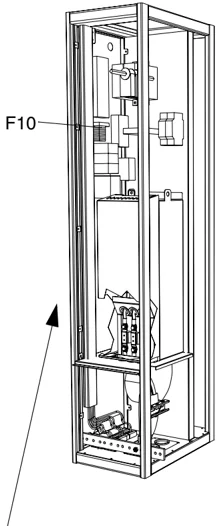
F10
Control cable connection: Connect the control cables to the appropriate terminal block on the DIN rail.
Motor cable connection
- Strip the cable 3 cm at the cabinet entry if EMC sleeves are used.
- Lead the cable unstripped to the busbar terminals behind the fan.
- Connect the cables to the terminals with cable lugs.
- Connect the shield conductor to the PE busbar.
Busbars for motor cable connection: U2, V2, W2.
Motor cables
PE terminal of the cabinet
ACA 6xx Sections and ACS/ACC 6x7 (132 to 3000 kW) Frequency Converters 3-19
Inverter Modules R8i and Above The cable connections of a bottom entry unit are represented below. For top exit, an extra cabinet is required (200 mm to 800 mm, see next page).
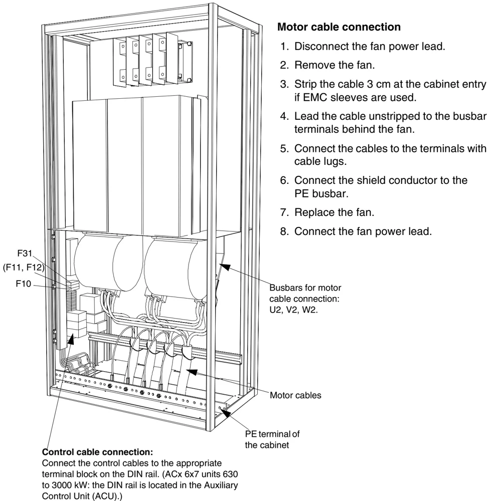
F31 (F11, F12) F10
Busbars for motor cable connection: U2, V2, W2.
Motor cables
PE terminal of the cabinet
Control cable connection: Connect the control cables to the appropriate terminal block on the DIN rail. (ACx 6x7 units 630 to 3000 kW: the DIN rail is located in the Auxiliary Control Unit (ACU).)
Motor cable connection
- Disconnect the fan power lead.
- Remove the fan.
- Strip the cable 3 cm at the cabinet entry if EMC sleeves are used.
- Lead the cable unstripped to the busbar terminals behind the fan.
- Connect the cables to the terminals with cable lugs.
- Connect the shield conductor to the PE busbar.
- Replace the fan.
- Connect the fan power lead.
3-20 ACA 6xx Sections and ACS/ACC 6x7 (132 to 3000 kW) Frequency Converters
Output Cubicle This cubicle is used for
- motor cable entry and exit through the top of the cabinet
- common motor output of parallel connected inverter modules R11i and R12i (optional)
- common motor output of parallel connected inverter modules when the number of cables does not match the rule given on page 3-15 (optional).
Cable entry from the bottom is shown below. The top entry is accomplished in the same way except that cables are entering or exiting the cabinet from the top.
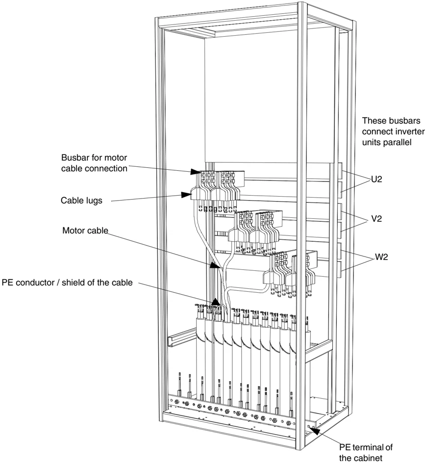
Busbar for motor cable connection Cable lugs Motor cable PE conductor / shield of the cable These busbars connect inverter units parallel U2 V2 W2 PE terminal of the cabinet
ACA 6xx Sections and ACS/ACC 6x7 (132 to 3000 kW) Frequency Converters 3-21
Conductive Sleeves Conductive sleeves are supplied by ABB as an option to provide 360° high-frequency earthing for motor cables. Follow these instructions:
- If fire insulation is used, make an opening to the mineral wool sheet according to the diameter of the cable.
- Pull the cable into the cabinet through the conductive sleeve.
- If a rubber grommet is used, slide it onto the cable.
- Connect phase conductors to terminals.
- Twist the shield wires of the cable together and connect them to earth terminal or PE busbar.
- Peel off 3 to 5 cm of the outer insulation of the cable above the entry plate for the 360° high-frequency earthing.
- Fasten the conductive sleeve to the cable shield with a cable tie.
- Seal the slot between the cable and mineral wool sheet (if used) with sealing compound (e.g. CSD-F, ABB brand name DXXT-11, code 35080082).
- Tie up the unused conductive sleeves with cable ties.
Cable Entry Cable entry from below for power cables of ACx 600 (IP 21 and IP 22) is shown below. Tighten the EMC sleeve on the stripped part of the cable with cable ties. For IP 54 units, add a rubber grommet on the cable under the lead-through plate.
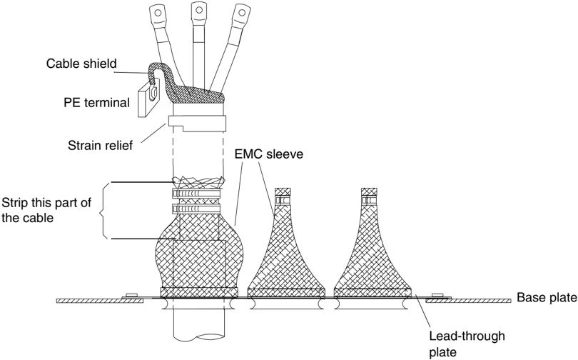
Cable shield PE terminal Strain relief EMC sleeve Strip this part of the cable Base plate Lead-through plate
ACA 6xx Sections and ACS/ACC 6x7 (132 to 3000 kW) Frequency Converters
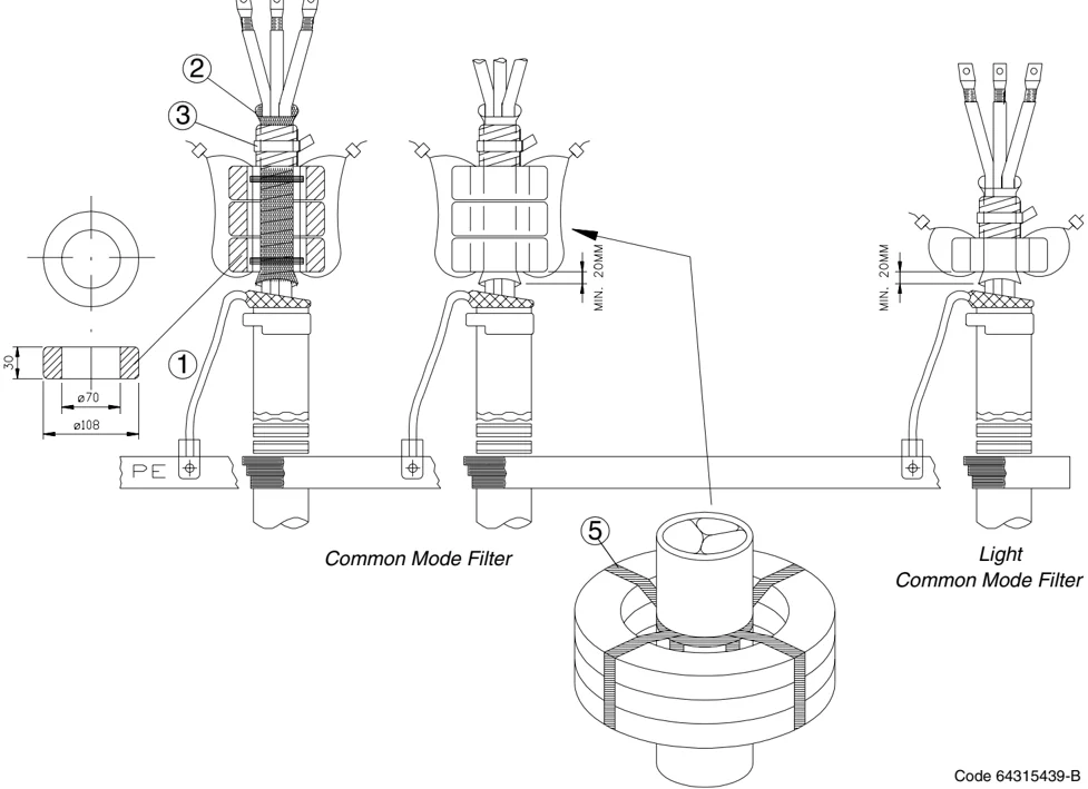
Common Mode Filter
If common mode filter or light common mode filter is required (see Motor Connections / Requirements Table in Safety Instructions), lead the motor cable phase conductors through the toroidal cores as follows:
- Connect the twisted cable screen to the PE terminal.
- Wrap the phase conductors together with the silicon rubber tape delivered with the toroidal cores to provide thermal insulation for the conductor insulator. Cover the part of the cable which will be left inside the core(s) + 20 mm below. Approximately 1.5 metres of tape is needed per cable. Each turn must overlap the previous turn by half the width of the tape.
- Bind the conductors tightly with non-conductive electrical tape and a heat-resisting non-metallic cable tie in order to prevent conductor insulation damage caused by the core edges.
- Slide the core(s) onto the taped part of the phase conductors.
- Bind the cores together and onto the taped part of the phase conductors with heat-resisting non-metallic cable ties.
ACA 6xx Sections and ACS/ACC 6x7 (132 to 3000 kW) Frequency Converters 3-23
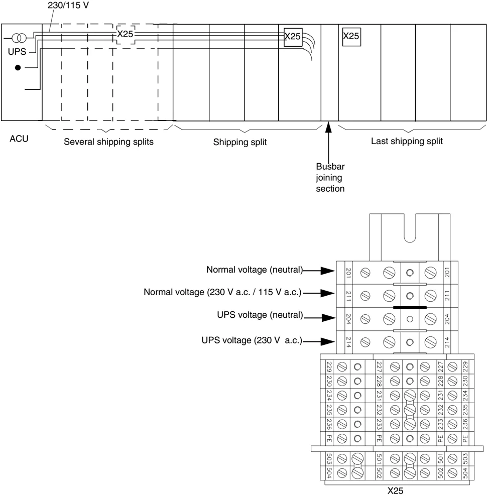
Control Cable Connections at Shipping Split Joints
Some control wires are chained through the shipping splits. 230/115 V voltage transformer, uninterrupted power supply (UPS) and emergency stop wires are chained via terminal blocks X25 at the upper left hand corner of the fields next to the busbar joining sections. Connect the loose wires to the next X25 terminal block. Connect the loose wires not coming from X25 to the destinations marked on the wire ends. Ensure that no unconnected wire ends are left which will be powered when the supply voltage is switched on.
3-24 ACA 6xx Sections and ACS/ACC 6x7 (132 to 3000 kW) Frequency Converters
External Control Cable Connections Connect the control cables to the appropriate terminals on the NIOC board (or optional terminal block X2, or other options on the DIN rail on the left-hand side of the cabinet). External control cables and options for ACx 6x7 units (630 to 3000 kW) are connected in the Auxiliary Control Unit (see subsection below). Connect the twisted screen (as short as possible) to the earthing terminal \text\textcircledE.
Auxiliary Control Unit of ACx 6x7 External control cables and options for ACx 6x7 units (630 to 3000 kW) are connected in a 400 mm or 600 mm wide Auxiliary Control Unit. NIOC board and X2/2TB terminal block are located on the DIN rail on the left-hand side of the cabinet.
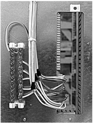
Assembly Door Wire the door options as shown below.
Assembly door viewed from back
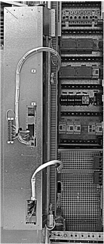
Connect the twisted inner screens (max 2 cm) of double shielded cables to the earthing rail.
Ensure that the cables are long enough for the assembly door to open.
ACA 6xx Sections and ACS/ACC 6x7 (132 to 3000 kW) Frequency Converters 3-25
360° Earthing at the Cable Entry 360° earthing of the control cable screens by EMI conductive cushions at the bottom of the Auxiliary Control Unit is shown below.
 EMI conductive cushions
ACA 6xx Sections and ACS/ACC 6x7 (132 to 3000 kW) Frequency Converters
EMC Earthing at the Cable Entry 360° high frequency earthing of the control cable screen at the cable entry is available as an option from ABB (figure below).
Side view Top view
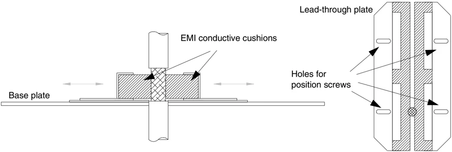
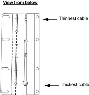
Special for Top Entry When each cable has its own rubber grommet, sufficient IP and EMC protection can be achieved. However, if very many control cables come to one cabinet, plan the installation beforehand as follows:
- Make a list of the cables coming to the cabinet.
- Sort the cables going to the left into one group and the cables going to the right into another group to avoid unnecessary crossing of cables inside the cabinet.
- Sort the cables in each group according to size.
- Group the cables for each grommet as follows:
- Divide the bunches so that cables will be arranged according to size between the EMI conductive cushions.
View from below
Thinnest cable
Thickest cable
Bottom and Top Entry Proceed as follows:
- Loosen the lead-through plate position screws. Pull the two parts apart.
- Bottom entry Lead the cable inside the cabinet through the EMI conductive cushions. Top entry Lead the cable inside the cabinet through the grommet and the EMI conductive cushions. If you have several cables, bunch them together at the grommet, but ensure that each cable has a proper contact to the cushions on both sides.
- Strip off the cable plastic sheath above the base plate (just enough to ensure proper connection of the bare screen and the EMI conductive cushions).
- Earth the screen between the EMI conductive cushions:
a. If the outer surface of the screen is conductive:
- Push the two parts of the lead-through plate together so that the EMI conductive cushions press tightly round the bare screen.
3-28 ACA 6xx Sections and ACS/ACC 6x7 (132 to 3000 kW) Frequency Converters
b. If the outer surface of the screen is covered with non-conductive material:
Stripped cable Conductive surface of the screen exposed Stripped part covered with copper foil
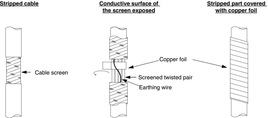
- Cut the screen at the midpoint of the bare part. Be careful not to cut the conductors.
- Turn the screen inside out to expose its conductive surface.
- Cover the turned screen and the stripped cable with copper foil to keep the shielding continuous. Note: The earthing wire (if present) must not be cut.
- Push the two parts of the lead-through plate together so that the EMI conductive cushions press tightly round the foil-covered screen.
- Lock the two parts of the lead-through plate by tightening the positioning screws.
ACA 6xx Sections and ACS/ACC 6x7 (132 to 3000 kW) Frequency Converters
- Top entry: If more than one cable go through a grommet, the grommet must be sealed by Loctite 5221 (catalogue number 25551).
Side view
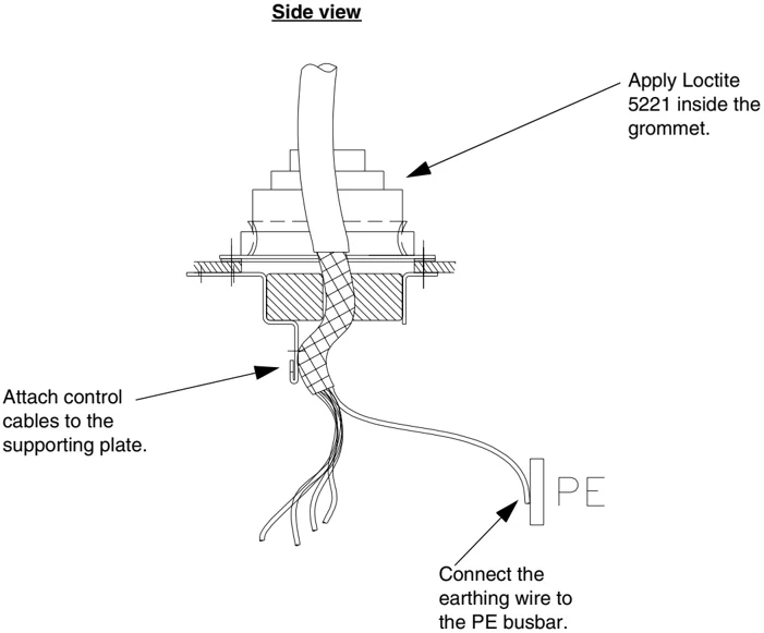
Apply Loctite 5221 inside the grommet.
Attach control cables to the supporting plate.
Connect the earthing wire to the PE busbar.
3-30 ACA 6xx Sections and ACS/ACC 6x7 (132 to 3000 kW) Frequency Converters
Drive Control Unit NDCU-2x
The Drive Control Unit NDCU-21 containing a NAMC-21 board and an NIOC-01 board is shown below. NDCU-22 with NAMC-22 and NIOC-01 looks similar.
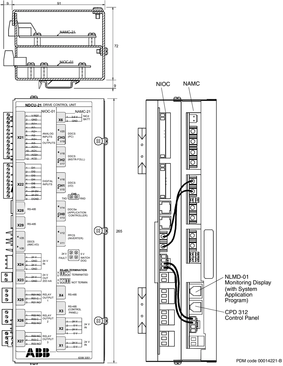
ACA 6xx Sections and ACS/ACC 6x7 (132 to 3000 kW) Frequency Converters
Drive Control Unit NDCU-51
The Drive Control Unit NDCU-51 containing an NAMC-51 board and an NIOC-01 board is shown below. NMBO-01 is an optional Memory Backup board.
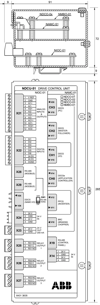
PDM code 00057607-A
3-32 ACA 6xx Sections and ACS/ACC 6x7 (132 to 3000 kW) Frequency Converters
NIOC Board Chaining
When several NIOC boards are daisy-chained for common control from an external Modbus device the bus termination switch (SW1) must be set on the participating boards as shown below.
Note: This chaining is not supported by System Application Program.
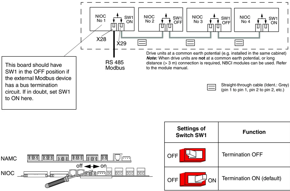
This board should have SW1 in the OFF position if the external Modbus device has a bus termination circuit. If in doubt, set SW1 to ON here.
Drive units at a common earth potential (e.g. installed in the same cabinet)
Note: When drive units are not at a common earth potential, or long distance (> 3 m) connection is required, NBCI modules can be used. Refer to the module manual.
Straight-through cable (Ident.: Grey)
(pin 1 to pin 1, pin 2 to pin 2, etc.)
| Settings of Switch SW1 | Function |
|---|---|
| OFF | Termination OFF |
| OFF ON | Termination ON (default) |
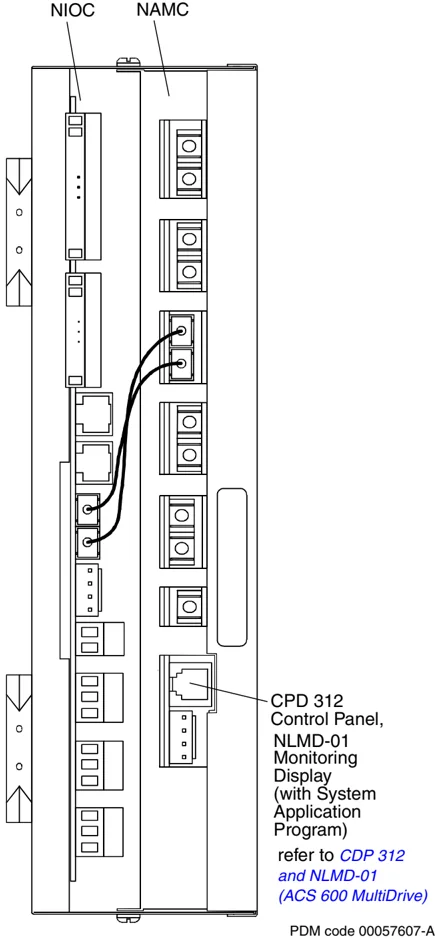
CDP 312 and NLMD-01 (ACS 600 MultiDrive) The wiring of the CDP 312 Control Panel and NLMD-01 Monitoring Display in ACS 600 MultiDrive units is shown below:
Symbols Reversed (crossover) cable (Ident.: Black) (pin 1 to pin 6, pin 2 to pin 5, etc.)
Straight-through cable (Ident.: Grey) (pin 1 to pin 1, pin 2 to pin 2, etc.)
• Control Panel and Monitoring Display
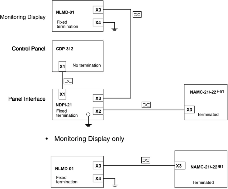
• Monitoring Display only
3-34 ACA 6xx Sections and ACS/ACC 6x7 (132 to 3000 kW) Frequency Converters
- one Control Panel is chained to many drive units
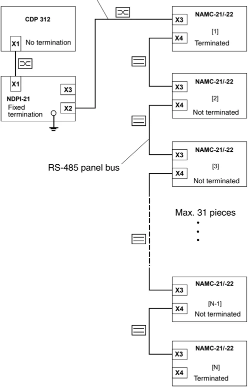
The CDP 312 Control Panel can be connected (through NDPI-21 or directly) to the NAMC-21/22 board to the 6-pin modular connector X3. The modular connectors on the NIOC board are not intended for the Control Panel.
The maximum cable length between CDP 312 (or NDPI-21) and NIOC-01 or NAMC-xx is 10 metres. In the presence of high-level radiofrequency disturbances, the length should be limited to 3 metres.
The maximum total length of the panel bus is 30 metres. With Panel Bus Connection Interface Module NBCI-01 the maximum panel bus length can be extended to 1200 metres (refer to NBCI-0x Module Installation and Start-up Guide)
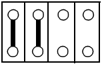
RS-485 Termination Settings When the Control Panel CDP 312 is connected to one NAMC-21/22 board only, the RS-485 line must be terminated on the NAMC-21/22 board by jumpers X5 as follows:
Terminated
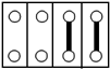
If CDP 312 is connected to several NAMC 21/22 boards (RS-485 panel bus), the first and the last NAMC 21/22 board must be terminated. The intermediate boards must not be terminated.
Not terminated
Earthing (Grounding) The boards are earthed to the chassis as shown below (back view of the Control Panel mounting platform.)
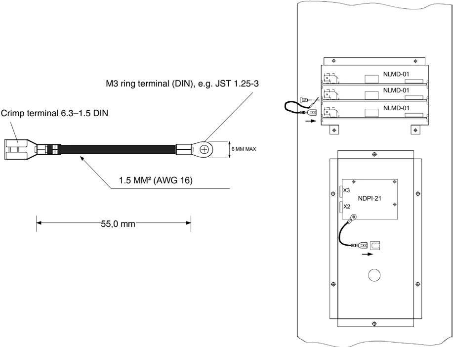
M3 ring terminal (DIN), e.g. JST 1.25-3 Crimp terminal 6.3–1.5 DIN 1.5 MM² (AWG 16) 6 MM MAX 55,0 mm
NLMD-01 NLMD-01 NLMD-01 X3 NDPI-21 X2
3-36 ACA 6xx Sections and ACS/ACC 6x7 (132 to 3000 kW) Frequency Converters
Control Panel Connection (ACx 6x7) The Control Panel is connected to modular jack X19 on NAMC-11/51 board. The modular jacks on NIOC board are not intended for Panel use (they are used by Standard Modbus Link).
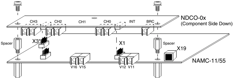
- with NAMC-51 for optional Memory Backup board (NMBO)
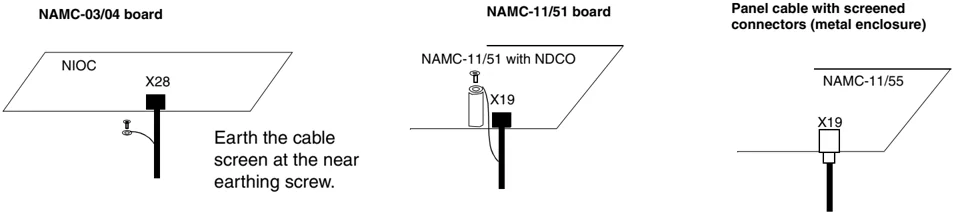
Control Panel in Remote Use (ACx 6x7) Connect the Control Panel cable to terminal X19 of the NAMC-11/51, or with NAMC-03 board to terminal X28 of the NIOC board.
NAMC-03/04 board NIOC X28 Earth the cable screen at the near earthing screw.
NAMC-11/51 board NAMC-11/51 with NDCO X19
Panel cable with screened connectors (metal enclosure) NAMC-11/55 X19
Pulse Encoder Installation See NIOB-01 User’s Guide (EN code 64471341) or Pulse Encoder Interface Module NTAC-0x Installation and Start-up Guide (EN code 58919730) for the pulse encoder insulation requirements and connections.
The pulse encoder shall be insulated from the motor stator or rotor in order to prevent currents from finding their way out from the drive shaft through the encoder with resulting damage to the bearings in both the motor and the encoder.
ACA 6xx Sections and ACS/ACC 6x7 (132 to 3000 kW) Frequency Converters
Installation of Optional Modules
This section gives general installation instructions for the DriveWindow PC tool and ACx 600 optional modules, such as fieldbus adapters, I/O extension modules and the pulse encoder interface. Connection examples are given at the end of the section.
Placement The module should be installed on the DIN mounting rail inside the inverter unit cabinet, located on the inside of the left-hand side cabinet wall. The DIN rail of ACx 6x7 units is located in the Auxiliary Control Unit (ACU). Follow the instructions given in the Mechanical Installation chapter of the module manual.
Power Supply for the Module The 24 V d.c. supply for one optional module is provided by the NIOC board of the inverter module (terminal X23). The NIOC board is assembled into the NDCU control unit, mounted on a DIN rail inside the inverter unit cabinet or in the Auxiliary Control Unit (ACx 6x7 units).
Fibre Optic Link Optional modules are connected via a DDCS fibre optic link to the NAMC board or NDCO board (both mounted on top of the NIOC board). The terminals to which the cables are connected on the NAMC/ NDCO board are given in the table below. Channel CH1 is on NAMC-11/51 board. Channels CH0, CH2 and CH3 are on the NDCO board. The NAMC-03 and NAMC-21/22 boards include channels CH0 to CH3.
The NAMC 11/51 board is used with ACx 6x7 units. The NAMC-21 and NAMC 22 boards are used with ACS 600 MultiDrive: NAMC-21 with AC 80 and NAMC 22 with the fieldbus.
\begin{tabular}{|l|l|l|} \hline Module Type & Channel & Terminals \ \hline Fieldbus Adapter Modules & CH0* & V13*, V14* \ \hline I/O Extension Modules & CH1 & V15, V16 \ \hline Pulse Encoder Interface Module & CH2* with ACS 600 Standard Application Program 5.x & V17*, V18* \ \cline{2-3} & CH1 with ACS 600 System, Crane Master/Follower and Template Application Program & V15, V16 \ \hline Double Pulse Encoder Interface Module (for ACP 600 only) & CH2* & V17*, V18* \ \hline DriveWindow $^{1)}$ & CH3* & V19*, V20* \ \hline \end{tabular}
- on the NDCO board when the NAMC-11/51 board is used. $^{1)}$ DriveWindow Light is connected via an NPCU RS-232/485 converter to the panel connector on the cover (or to modular jack X19 on the NAMC-11/51 board).
Observe colouring codes when installing fibre optic cables. Blue connectors should go to blue terminals, and grey connectors to grey terminals.
In case multiple modules are installed on the same channel, they must be connected in a ring.
Optical Components The optical transmitter and receiver types (5 MBd or 10 Mbd) in DDCS channels CH0 to CH3 on the NAMC boards are given below.
\begin{tabular}{|l|c|c|c|c|c|c|} \hline DDCS & \multicolumn{6}{c|}{Optical Transmitter/Receiver Type} \ \cline{2-7} Channel & NAMC-11/51 Board & \multicolumn{3}{c|}{DDCS Communication Option} & NAMC-21 Board & NAMC-22 Board \ \cline{3-5} & & NDCO-01 & NDCO-02 & NDCO-03 & & \ \hline CH0 & - & 10 MBd (DriveBus) & 5 MBd & 5 MBd & 10 MBd (DriveBus) & 5 MBd \ \hline CH1 & 5 MBd & - & - & - & 5 MBd & 5 MBd \ \hline CH2 & - & 10 MBd & 10 MBd & 5 MBd & 10 MBd & 10 MBd \ \hline CH3 & - & 10 MBd & 10 MBd & 5 MBd & 10 MBd & 10 MBd \ \hline \end{tabular}
Note 1: When connecting an NAMC board to another unit make sure, that the optical components are of the same type at both ends of the link. Do not mix 5 MBd and 10 MBd transmitters and receivers.
Note 2: With 5 MBd optical components only plastic optical cable (POF) can be used. The maximum cable length is 10 metres. However, when operating at the lower speed of 1 Mbit/s (normally with DriveWindow) the cable length can be extended to 15 metres.
Note 3: With 10 MBd components either plastic (POF) or Hard Clad Silica (HCS) optical cable can be used. When the maximum optical power (transmitter current) is selected by the software, the following cable lengths are applicable:
\begin{tabular}{|l|c|} \hline Cable & NAMC-21/22/51 Board \ \cline{2-2} & Cable length (m) \ \hline POF & 30 \ \hline HCS & 200 \ \hline \end{tabular}
ACA 6xx Sections and ACS/ACC 6x7 (132 to 3000 kW) Frequency Converters 3-39
Connection Examples
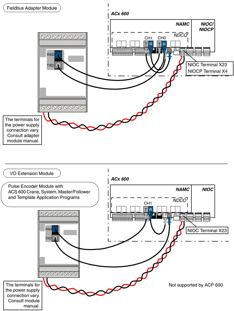
The terminals for the power supply connection vary. Consult adapter module manual.
The terminals for the power supply connection vary. Consult module manual.
Not supported by ACP 600
3-40 ACA 6xx Sections and ACS/ACC 6x7 (132 to 3000 kW) Frequency Converters
Connection Examples
Pulse Encoder Module (NTAC) with ACS 600 Standard Application Program
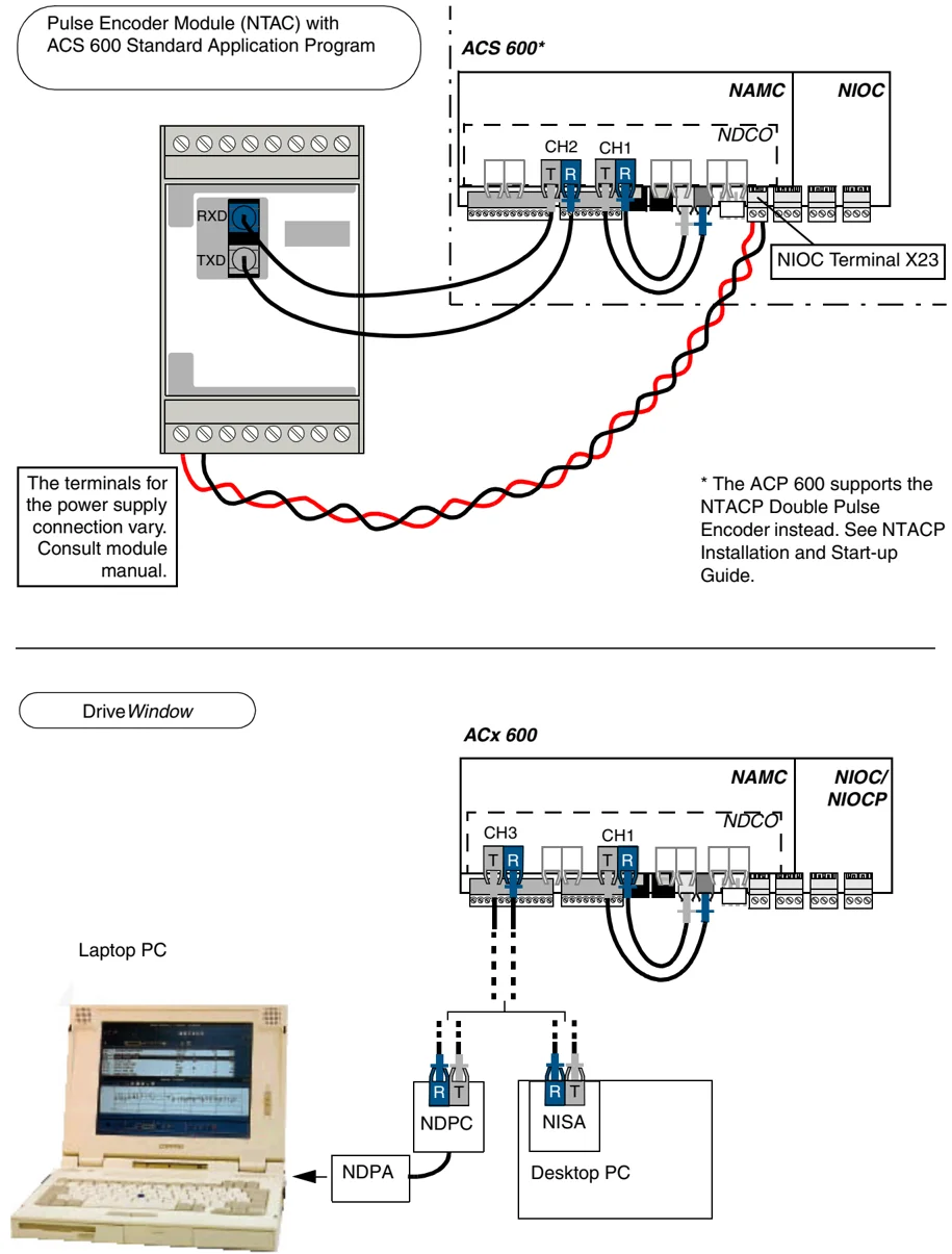
The terminals for the power supply connection vary. Consult module manual.
- The ACP 600 supports the NTACP Double Pulse Encoder instead. See NTACP Installation and Start-up Guide.
DriveWindow
Laptop PC
ACA 6xx Sections and ACS/ACC 6x7 (132 to 3000 kW) Frequency Converters
Installation of Other Optional Equipment Install options such as PTC/PT100 relays, cubicle heater, motor fan starter etc. according to circuit diagrams delivered with the unit.
3-42 ACA 6xx Sections and ACS/ACC 6x7 (132 to 3000 kW) Frequency Converters