Chapter 4 – Installation Checklist
Installation Checklist The mechanical and electrical installation of ACS 600 MultiDrive should be checked before start-up. It is advisable to go through the checklist below together with another person. Study carefully the Safety Instructions on the first pages of this manual before attempting any work on, or with, the unit.
INSTALLATION CHECKLIST
Check
MECHANICAL INSTALLATION
☐ The ambient operating conditions are acceptable. (See Safety and Product Information: environmental limits, cooling air flow requirements, free space requirements)
☐ The unit is fixed properly. (See Chapter 2 – Mechanical Installation)
☐ Cooling air will flow freely:
- the lifting bars (if used) are removed. (See Chapter 2 – Mechanical Installation)
- the cabinet roof is lifted up (if double roof). (See Chapter 2 – Mechanical Installation)
☐ The applicability of the motor and the driven equipment. (See Safety and Product Information: Motor Connection)
ELECTRICAL INSTALLATION (see Chapter 3 – Electrical Installation)
☐ Joining of the shipping splits:
- The DC busbars and PE busbars are properly connected (See Chapter 2 – Mechanical Installation: Connecting the DC Busbar and the PE Busbar)
- The control cables are properly connected. (See Chapter 3 – Electrical Installation: Control Cable Connection at Shipping Split Joints)
☐ The converter unit is earthed properly.
☐ The mains voltage matches the frequency converter nominal input voltage.
☐ The setting of the internal 220/115 V transformer corresponds to the supply voltage. The transformer is located in the Auxiliary Control Unit.
☐ The mains (input power) connections at U1, V1 and W1 are OK.
ACS 600 MultiDrive 4-1
Chapter 4 – Installation Checklist
INSTALLATION CHECKLIST
☐ The appropriate mains fuses are installed (see Safety and Product Information and Supply Units User’s Manual).
☐ The appropriate DC fuses are installed (see Safety and Product Information and Supply Units User’s Manual)).
☐ The motor is of correct voltage.
☐ The motor star/delta connection at the motor terminal box is correct.
☐ Motor cable routing.
☐ Check that the toroidal cores are properly installed on the motor cable when a common mode filter is required.
☐ The motor connections at U2, V2 and W2 are OK.
☐ There are no power factor compensation capacitors in the motor cable.
☐ The control connections inside the cabinet are OK.
☐ If pulse encoder is used, check the encoder cables and correct direction of rotation (see Chapter 3 – Electrical Installation: Installation of Optional Modules and Pulse Encoder Interface Module NTAC-02 Installation and Start-up Manual EN code 58919730 or NIOB-01 User’s Guide EN code 64471341)
☐ Thermistor cables. The connections are appropriate for the sensor used in the motor.
☐ Prevention of Unexpected Start cables.
☐ Emergency stop cables.
☐ When other external cables are used make sure that both ends of the cables are connected and the cables do not cause any damage or danger when power is being switched on.
☐ Cleanliness of the cabinet and surroundings, e.g.:
- there are no tools or other foreign objects inside the cabinet or waste left from installation e.g. cable trimmings
- there is no garbage under the cabinet (the cooling air fan will draw the garbage inside the cabinet)
☐ Mains voltage cannot be applied to the output of the ACx 600 (with bypass connection).
4-2 ACS 600 MultiDrive
Chapter 5 – Commissioning the Drive Section
Overview
This chapter describes the hardware commissioning of an ACS 600 MultiDrive drive section. For the drive control firmware commissioning refer to the application program Firmware Manual (for System, Standard, Crane Drive or other Application). For supply section commissioning refer to Supply Sections User’s Manual (DSU, TSU or ISU).
WARNING! The work described in this chapter must only be carried out by a qualified electrician. The Safety Instructions on the first pages of this manual must be followed. Negligence of the safety instructions can cause injury or death.
Installation Checklist
The installation must be checked before commissioning the Drive Section.
| Action | Information |
|---|---|
| ☐ Check that the mechanical and electrical installation of the frequency converter is inspected and OK. | See Chapter 4 – Installation Checklist. |
| ☐ Ensure that the insulation resistance of the assembly is checked according to the instructions. | See Insulation Checks in Chapter 3. |
| ☐ Ensure that the surroundings and inside of the cabinet is free from dust and loose objects (like cable trimmings and other waste left from the installation). | After the start, the cooling air fans may suck nearby loose objects into the unit. This might cause failure and damage the unit. |
ACS 600 MultiDrive
Chapter 5 – Commissioning the Drive Section
Checks with No Voltage Connected
The table below is a commissioning checklist for the Drive Section with no voltage connected.
| Action | Information |
|---|---|
| WARNING! Ensure that the disconnector of the supply transformer is locked to open position, i.e. no voltage is, or can be connected to the ACx 600 inadvertently. Check also by measuring that no voltage is actually connected.If the motor has a safety switch, make sure that it is open. If the motor has no safety switch, open the circuit Prevention of Unexpected Start (if available). | |
| 1. Drive DataFind out the following data for each drive section and note down any differences in delivery documents:☐ Motor, pulse encoder and cooling fan rating plate data correspond to the values in the motor list.☐ Motor temperature measurement method: Pt 100, PTC or other.☐ Motor fan of separately ventilated motors. Check the current, the overcurrent protection setting and the functioning of the fan output control circuit.☐ Direction of motor rotation☐ Maximum and minimum speeds, fixed speeds☐ Speed scaling factor, gear ratio, roll diameter etc.☐ Acceleration and deceleration times☐ How inertia compensation is performed☐ Operating modes: stop mode etc.☐ The number of motors in the section | |
| 2. Voltage for the Cooling FansFrame sizes R2i to R7i: The fan motor protection and 24 V auxiliary voltage switch (F10) is on.Frame sizes R8i and above: The fan motor protection switches (F10 (and F11, F12)) and 24 V auxiliary voltage switch (F31) are on. | See the circuit diagrams delivered with the device. Chapter 1 – Introduction: Voltages from the Supply Section, Chapter 3 – Electrical Installation: Motor Cable Connections.as above |
ACS 600 MultiDrive
Connecting Voltage to Auxiliary Circuits
The table below describes how to connect voltage to the Supply Section input terminals and to the Auxiliary Control Unit (ACU) for the first time.
| Action | Information |
|---|---|
| WARNING! When voltage is connected to the input terminals of the Supply Section, the voltage will also be connected to the Auxiliary Control Unit and to auxiliary circuits - also to the ones wired to drive sections.Make sure that it is safe to connect voltage to the input terminals. Ensure that while the voltage is connected:• Nobody is working on the unit or circuits that are wired from outside into the cabinets.• The cabinet doors are closed. | |
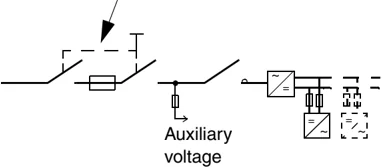
| ☐ Disconnect the 230 VAC cables that lead from the terminal blocks to the outside of the equipment and have not yet been checked, and the connections which may not yet have been completed.☐ Disconnect the communication link to the overriding system by removing the fiber optic cables.☐ Make sure that the main contactor/air circuit breaker cannot be closed inadvertently by remote control, e.g. by temporarily opening a connection in its control circuit.☐ Be ready to trip the main breaker of the supply transformer in case something abnormal occurs.☐ Ensure that all cabinet doors are closed.☐ Close the main breaker of the supply transformer.☐ Frame sizes B1, B2, B3 and B4 type ACA 631-0850-61-xx: Close the main disconnecting switch of the Supply Section. | See the circuit diagrams delivered with the device. |
ACS 600 MultiDrive
Chapter 5 – Commissioning the Drive Section
| Action | Information |
|---|---|
| ☐ Frame sizes B4 and up (except ACA 631-0850-61-xx):Close the main disconnecting switch of the auxiliary circuit. |
Checks with Voltage Connected to Auxiliary Circuits
The table below is a commissioning checklist for the Drive Section with voltage connected to the input terminals, and to Auxiliary Control Unit (ACU).
| Action | Information |
|---|---|
| WARNING! This section includes instructions for checking/measuring circuits under voltage. Only a qualified person is allowed to do the work. Appropriate and approved meter must be used.IF IN DOUBT, DO NOT PROCEED! | |
| ☐ Ensure the actions described in section Connecting Voltage to Auxiliary Circuits are completed. | |
| ☐ Close the optional disconnecting switch of the drive section (if included). | See section Connecting Voltage to Drive Section below. |
| 1. Cooling Fans | |
| ☐ Check that the cooling air fans rotate freely in the right direction, and the air flows upwards. | A paper sheet set on the lower gratings stays. The fan runs noiselessly. |
| 2. Parameters | |
| ☐ Set the drive parameters according to the application Firmware Manual (System, Standard, Crane Drive or other). With Standard Application Program, use the Start-up Guide. | |
| ☐ A hardware interlock from main switches of every inverter module is connected to digital input DI2. Check that DI2 is configured to RUN ENABLE. | See Firmware Manual. |
| After the Checks | |
| ☐ Open the optional disconnecting switch of the drive section (if included). |
ACS 600 MultiDrive
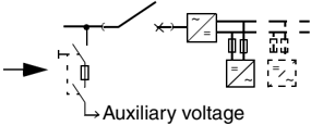
Connecting Voltage to Drive Section
The table below describes how to connect voltage to the Drive Section.
| Action | Information |
|---|---|
| WARNING! When connecting voltage to the Supply Unit, the DC busbars will become live, as will all the inverters connected to the DC busbars.Make sure that it is safe to connect voltage to the Supply Unit. Ensure that:• Nobody is working on the unit or circuits that are wired from outside into the cabinets.• It is safe to start the motor.• All cabinet doors are closed.WARNING!Drive Section with a disconnecting switchWhen the drive section disconnecting switch (switch fuse) and the main breaker/contactor of the Supply Section are closed, the drive section is powered through the charging circuitry even though the main fuses of the drive section (e.g. fuses in the switch fuse) are removed. When the drive section disconnecting switch is opened the fuses in it can be removed and inserted but not the charging circuit fuses which are live!Drive Section without a disconnecting switchIf the drive sections only have fuses without a main switch, all the sections which have the fuses installed will be powered to a voltage of 1.35· U₁ when the main breaker/contactor closes. To prevent this, remove the fuses from the drive sections which you do not wish to receive power. If the drive section is not equipped with a main switch, the drive section must only be energised/de-energised by operating the main breaker/contactor in the supply section. When the main breaker/contactor of the Supply Section is closed (DC busbar is live), never remove or insert the fuses of a drive section. |
DRIVE SECTION EQUIPPED WITH AN OPTIONAL MAIN DISCONNECTING SWITCH
| 1. | Frames R2i to R4i |
|---|---|
| Turn the main disconnecting switch of the drive section (switch fuse) to ON position. | Charging circuit is implemented internally. After the charging is finished, a relay contact will bypass the resistor. |
| 2. | Frames R5i to R6i |
|---|---|
| Turn the main disconnecting switch of the drive section (switch fuse) to ON position. | Charging circuit is implemented internally. After the charging is finished, a relay contact will bypass the resistor. |
ACS 600 MultiDrive
Chapter 5 – Commissioning the Drive Section
| Action | Information |
|---|---|
| 3. Frames R7i to R12 equipped with a Disconnecting Switch with Charging Circuitry | |
| Turn the main disconnecting switch (switch fuse) of the drive section to the CHARGE position. (A locking mechanism will prevent you from turning the handle further.) Keep the handle in this position a few seconds until the beeping sound stops, indicating that the intermediate circuit capacitors have been charged.Relieve the handle slightly to release the locking mechanism, then turn it to the ON position. | |
| DRIVE SECTION NOT EQUIPPED WITH A MAIN SWITCH | |
| Go to the next step (POWERING THE DRIVE SECTION). | |
| POWERING THE DRIVE SECTION | |
| WARNING! Before power switch-on, make sure that a sufficient inverter power is connected to the intermediate circuit. Rules of thumb:1. The sum power of the inverters connected must be at least 30% of the sum power of all inverters.2. The sum power of the inverters connected must be at least 30% of the rated power of the braking section (Pbr.max) if present.If the above mentioned rules are not followed, the DC fuses of the connected inverter(s) may blow or the braking chopper (if used) may be damaged. | |
| ☐ Ensure that the number of inverters connected to the intermediate circuit is sufficient.☐ Close the main contactor (or circuit breaker) of the Supply Section. | See the WARNING above.The drive section is powered. |
ACS 600 MultiDrive
Chapter 5 – Commissioning the Drive Section
Checks with Voltage Connected to Drive Section
Basic checks for the Drive Section when voltage is connected to the Supply Section and DC busbars.
| Action | Information |
|---|---|
| 1. Basic Checks | |
| ☐ Check that the Prevention of Unexpected Start (if available) is working.1. Stop the drive by a Stop command and wait until the drive has stopped.2. Open the Prevention of Unexpected Start switch by closing the switch on the control desk: the circuit will open. The lamp (if fitted) on the desk should be lit.3. Give a Start command. The drive should not start.4. Reset the drive. | See the circuit diagrams delivered with the device. |
On-load Checks
The table below is a commissioning checklist for the loaded Drive Section.
| Action | Information |
|---|---|
| ☐ Check the rotation direction of the motor. | |
| ☐ Check the pulse encoder functioning (if used) | See Pulse Encoder Interface Module NTAC-02 Installation and Start-up Manual (EN code 58919730) or NIOB-01 User’s Guide (EN code 64471341). |
| ☐ Check the emergency stop function of the system from each operating place. |
ACS 600 MultiDrive
Chapter 5 – Commissioning the Drive Section
Control from Overriding System
After the drive has been commissioned and tested locally, functional tests from the overriding system are performed. A checklist is below.
| Action | Information |
|---|---|
| 1. Disconnect all voltages. | |
| 2. Connect the communication link to the overriding system by connecting the fibre optic cables. | See the circuit diagrams delivered with the device. |
| 3. Power the unit up. | |
| 4. Check□ the start/stop functions□ torque etc. references□ alarm/fault words□ function in case of a communication break□ updating interval of the drive software□ other needed points of the application |
Disconnecting/Reconnecting of a Drive Section
If disconnecting or reconnecting of a drive section is needed proceed as follows.
| Action | Information |
|---|---|
| If disconnecting of a Section is needed | |
| □ 1. Stop the drive by a Stop command and wait until the drive has stopped.2. Open the Prevention of Unexpected Start switch (if present) to prevent accidental start.3. Open the main switch of the section (if present). | |
| If reconnecting of a Section is needed | |
| □ 1. Close the main switch of the section (if present).2. Close the Prevention of Unexpected Start switch (if present).The section is now ready for operation. | See section Connecting Voltage to Drive Section above. |
ACS 600 MultiDrive
Chapter 6 – Preventive Maintenance
WARNING! Before performing any maintenance on the equipment, the Safety Instructions on the first pages of this manual must be followed. Negligence of these instructions can cause injury or death.
If installed in an appropriate environment, the ACx 600 requires very little maintenance.
An annual check-up for dust and corrosion accumulation on the surfaces inside the cabinet is recommended.
Air Filters When having filtering for cooling air, check and clean or replace filter mats if dirty. Wash dirty filter mats with water (60 °C) and detergent.
Heatsink The ACx 600 can run into overtemperature faults if the heatsink is not clean. In normal environment, the heatsink should be checked and cleaned annually.
Use compressed air to remove dust from the heatsink. (The airflow direction must be from bottom to top.) Also, use a vacuum cleaner at the air outlet to trap the dust. Fan rotation must be prevented in order to prevent bearing damage.
Relays Relays should be checked for function and all connections should be inspected and checked for tightness. Any signs of corrosion, especially in ground components, shall be cleaned off.
Fan The cooling fan lifespan is approximately 40 000 hours. The actual lifespan depends on the frequency converter usage and ambient temperature.
Fan failure can be predicted by increasing noise from fan bearings and gradual rise in the heatsink temperature in spite of heatsink cleaning. If the frequency converter is used in a critical part of a process, fan replacement is recommended once these symptoms appear.
Spare Modules If spare modules are available, it is recommended to replace the cabinet modules with their spare modules once a year in order to avoid capacitor reforming and to equalize wear and tear on the modules. See section Capacitors below.
ACS 600 MultiDrive
Chapter 6 – Preventive Maintenance
Capacitors The ACx 600 intermediate circuit employs several electrolytic capacitors. The lifespan of the capacitors is approximately 100 000 hours, depending on the frequency converter loading and the ambient temperature.
Capacitor life can be prolonged by lowering the ambient temperature. It is not possible to predict capacitor failure.
Capacitor failure is usually followed by a mains fuse failure or a fault trip. Contact ABB if capacitor failure is suspected. Replacements are available from ABB. Do not attempt operation with other than ABB specified spare parts.
Reforming Converter DC link capacitors need to be reformed (re-aged) if the converter has been non-operational for more than one year. Without reforming capacitors may be damaged when the converter starts to operate. The reforming methods introduced here require that the converter has been stocked clean and dry. It is recommended to reform the capacitors once a year.
How to check the converter age Converter serial number defines the week, when the converter has been built:
- 8 digit: e.g. 18250125, 1 denotes manufacturing country (1 = Finland), 8 manufacturing year (1998), 25 manufacturing week and 0125 running manufacturing number.
- 10 digit: e.g. 1983200725, 1 denotes manufacturing country, 98 manufacturing year, 32 manufacturing week and 00725 running manufacturing number.
Reforming time The intermediate circuit of the converter is kept at its nominal voltage for the reforming time to “wake up” the capacitors. The reforming time required depends on how long the converter has been stocked (non-operational).
6-2 ACS 600 MultiDrive
Chapter 6 – Preventive Maintenance
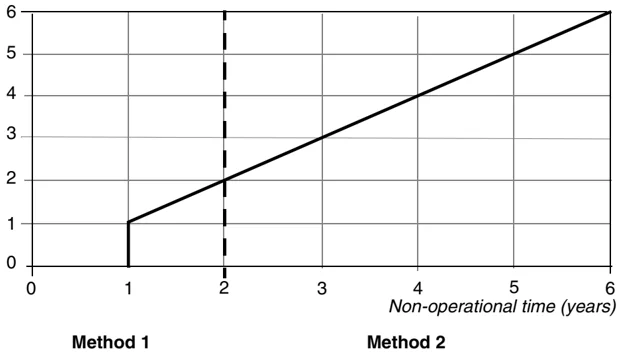
Figure 6-1. Capacitor reforming time for Method 1 and Method 2.
Converters Stocked (Non-operational) for Less Than 2 years
Switch the power on to the converter for a time given in Figure 6-1 (Method 1). The converter “wakes up” its capacitors by itself. Power the converters up once a year to keep the capacitors in operational condition.
Converters Stocked (Non-operational) for 2 Years and Over
Use Method 2 A or Method 2 B (both explained below) for capacitor reforming if the converter has been stocked or non-operational for two or more years.
WARNING! The ACS 600 MultiDrive converters (IGBT Supply Units and Drive Units) must be reformed outside the cabinet. Reform the phase modules separately outside the cabinet.
ACS 600 MultiDrive
Chapter 6 – Preventive Maintenance
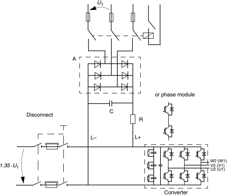
Method 2 A Capacitor reforming is realised by connecting a rectifier and a resistor circuit to the converter DC link. The reforming circuit and component values for different voltages are given below. See Figure 6-1 for the reforming time.
WARNING! The converter supply must be disconnected while the reforming circuit is connected.

| Supply Voltage | Recommended Components | ||
|---|---|---|---|
| A | R | C | |
| 380 V < U₁ < 415 V | SKD 82/16 | 220 Ohm / 700 W | 22 nF / 2000 V |
| 380 V < U₁ < 500 V | SKD 82/16 | 470 Ohm / 1200 W | 22 nF / 2000 V |
| 525 V < U₁ < 690 V | SKD 82/16 | 680 Ohm / 1700 W | 22 nF / 2000 V |
ACS 600 MultiDrive
Chapter 6 – Preventive Maintenance
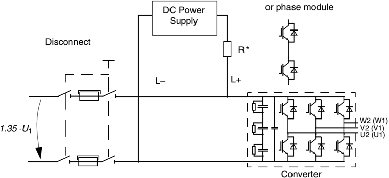
Method 2 B Capacitor reforming is based on a DC power supply connected to the converter DC link. Power supply current charges converter capacitors. If power supply cannot limit the current, voltage is increased gradually (with e.g. 100 V steps). Maximum recommended reforming current is 500 mA. An appropriate reforming voltage is (1.35... \sqrt2) \cdot U_1. The reforming circuit is shown below. See Figure 6-1 for the reforming time.
⚠️ WARNING! The converter supply must be disconnected while the reforming circuit is connected.

- R = 100 Ohm / 500 W
ACS 600 MultiDrive
Chapter 6 – Preventive Maintenance
6-6 ACS 600 MultiDrive
This page is blank. No content found to transcribe.

ABB Industry Oy Drives P.O. Box 184 FIN-00381 HELSINKI FINLAND Telephone +358 10 22 2000 Telefax +358 10 22 22681 Internet http://www.abb.com/automation
3AFY 63700118 R0125 REV E EFFECTIVE: 2.5.2001 EN