Chapter 2 – Mechanical Installation
Cable Conduit in the Floor below the Cabinet
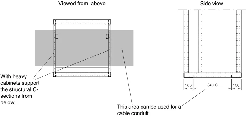
A cable conduit can be constructed below the 400 mm wide middle part of the cabinet. The cabinet weight lies on the two 100 mm wide transverse sections which the floor must carry.
Viewed from above
Side view
With heavy cabinets support the structural C-sections from below.
This area can be used for a cable conduit
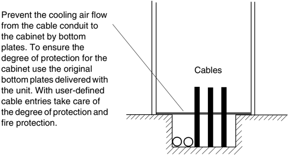
Prevent the cooling air flow from the cable conduit to the cabinet by bottom plates. To ensure the degree of protection for the cabinet use the original bottom plates delivered with the unit. With user-defined cable entries take care of the degree of protection and fire protection.
Cables
ACA 6xx Sections and ACS/ACC 6x7 (132 to 3000 kW) Frequency Converters 2-9
Chapter 2 – Mechanical Installation
Electric Welding It is not allowed to fasten cabinets equipped with vibration dampers by welding because the damper bolts would be welded to the cabinet frame as well and the dampers would be damaged.
Cabinets without vibration dampers can be welded (although it is not not recommended) from bottom as follows. Connect the return conductor of the welding equipment low to the cabinet frame within 0.5 metres of the welding point.

WARNING! If the welding return wire is connected improperly, the welding circuit may damage electronic circuits located in the cabinets.
2-10 ACA 6xx Sections and ACS/ACC 6x7 (132 to 3000 kW) Frequency Converters
Chapter 2 – Mechanical Installation
Vibration Dampers on Top and Bottom (Marine Versions)
The shipping split must be fastened to the floor and roof (wall) in marine versions as follows.
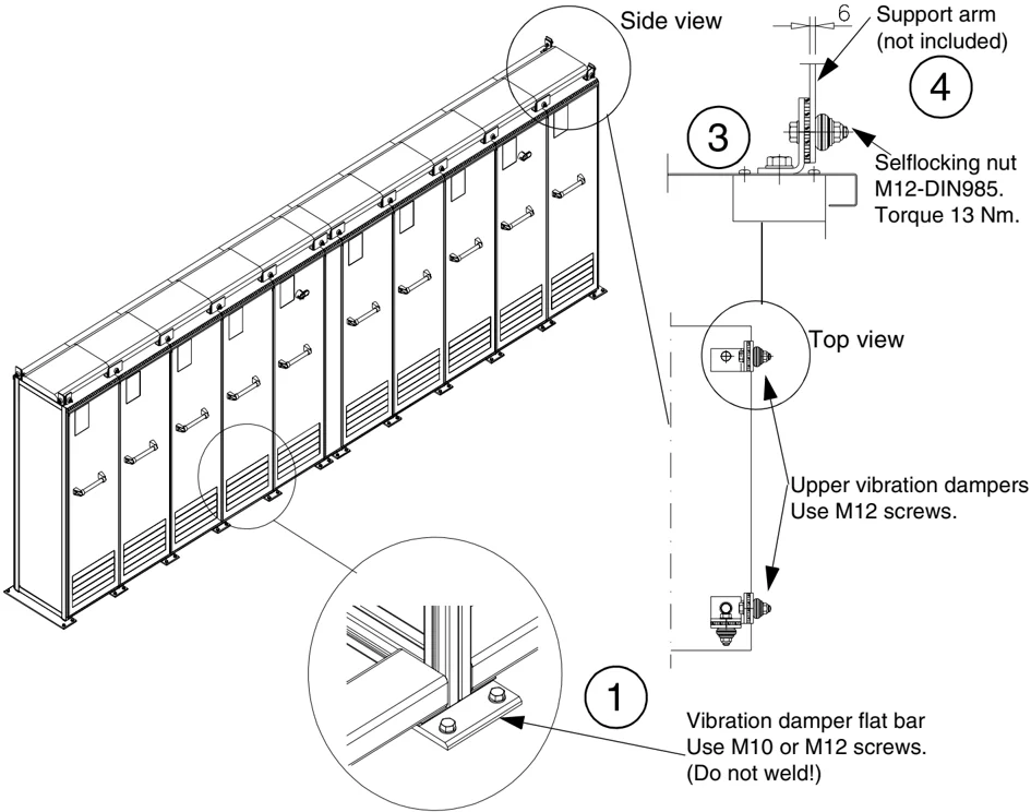
- Fasten the shipping split to the floor with M10 or M12 bolts through the holes in the vibration damper flat bar.
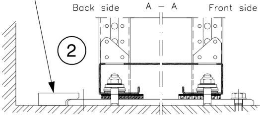
- If there is not enough room behind the cabinets for installation, use the fastening method shown in figure (2).
- Fasten the upper vibration dampers. For the positions of the upper vibration dampers, see the accompanying dimension drawing of the shipping split!
- Fasten the support arms to the upper vibration dampers and roof (wall).
ACA 6xx Sections and ACS/ACC 6x7 (132 to 3000 kW) Frequency Converters 2-11
Chapter 2 – Mechanical Installation
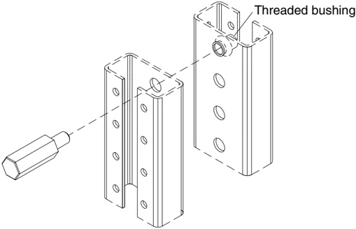
Joining the Shipping Splits Shipping splits are joined in the busbar joining section. Special screws (M6) for fastening the cabinets together are enclosed in a plastic bag inside the last cabinet of the shipping split. The threaded bushings are already mounted on the post.
Working Order
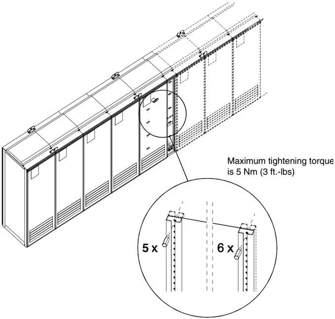
- Fasten the front post of the joining section with six screws to the front frame post of the next cabinet.
2-12 ACA 6xx Sections and ACS/ACC 6x7 (132 to 3000 kW) Frequency Converters
Chapter 2 – Mechanical Installation
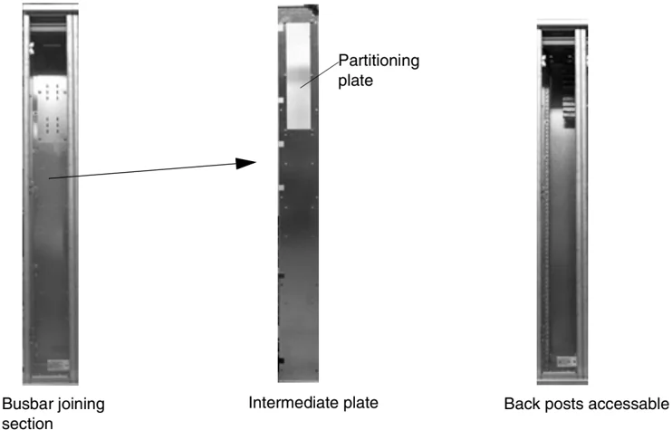
- 200 mm wide joining section: Remove the intermediate plate hiding the back posts in the joining section. 600 mm wide joining section: Remove the partitioning plates.
Busbar joining section
Intermediate plate
Back posts accessable
- Fasten the back post of the joining section with five screws (below the busbar joining part) to the post of the next cabinet.
- Replace the intermediate plate (and the partitioning plate(s) in the
- upper part of it after connecting the DC Busbars, see next page).
ACA 6xx Sections and ACS/ACC 6x7 (132 to 3000 kW) Frequency Converters 2-13
Chapter 2 – Mechanical Installation
Connecting the DC Busbar and the PE Busbar
Horizontal main DC busbars and the PE busbar are connected from the front of the 200/600 mm wide busbar joining cabinet. All necessary materials are located in the joining cabinet.
- Remove the front metal partitioning plate located in the busbar joining cabinet. 2 Unscrew the bolts of the joint pieces.
- Connect the busbars with the joint pieces (see figure below). For aluminium busbars, joint grease (e.g. TK-Penetral, made by Framatome Connectors USA Inc. Burndy Electrical) must be used to avoid corrosion and to ensure good electrical connection. The oxide layer must be scrubbed off from the joints before applying the grease.
- Replace the front metal plate into its original position because of safety of personnel.
DC Busbar The DC busbar connection is shown below.
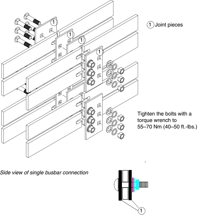
① Joint pieces
Tighten the bolts with a torque wrench to 55–70 Nm (40–50 ft.-lbs.)
Side view of single busbar connection
2-14 ACA 6xx Sections and ACS/ACC 6x7 (132 to 3000 kW) Frequency Converters
Chapter 2 – Mechanical Installation
PE Busbar The PE busbar connection is shown below.
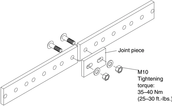
Joint piece M10 Tightening torque: 35–40 Nm (25–30 ft.-lbs.)
Lifting a Double Roof When the drive is equipped with a double roof:
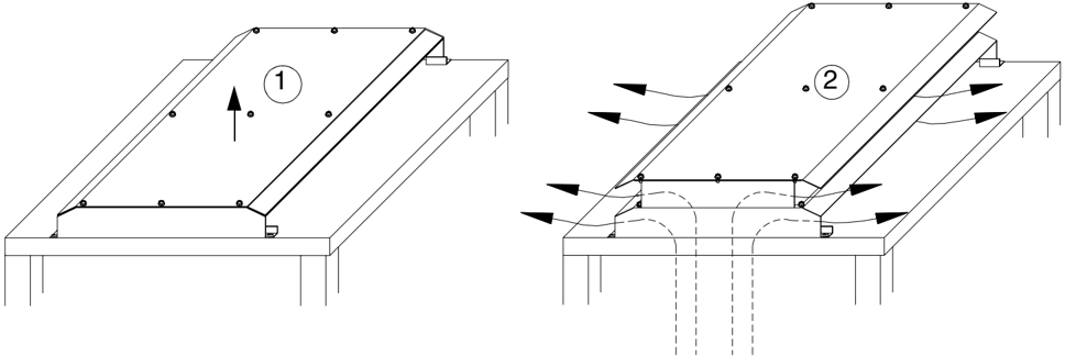
- Lift the upper part of the roof plate up from the transportation position.
- Lock the roof to its final position with the M6 screws.
ACA 6xx Sections and ACS/ACC 6x7 (132 to 3000 kW) Frequency Converters 2-15
Chapter 2 – Mechanical Installation
2-16 ACA 6xx Sections and ACS/ACC 6x7 (132 to 3000 kW) Frequency Converters
Chapter 3 – Electrical Installation
WARNING! The electrical installation described in this chapter should only be carried out by a qualified electrician. The Safety Instructions on the first pages of this manual must be followed. Negligence of these instructions can cause injury or death.
ACA 6xx Sections and ACS/ACC 6x7 (132 to 3000 kW) Frequency Converters 3-1
Power Cable Selection
The mains and motor cables must be dimensioned according to local regulations:
- The cable must be able to carry the ACx 600 load current. See Safety and Product Information (or Appendix A for ACx 6x7) for cable types for different load currents.
- The cable terminals of the ACx 600 warm up to 60 °C (140 °F) during operation. The cable must be rated for at least 60 °C (140 °F) maximum operating temperature.
- The cable must withstand the short-circuit current given in Mains Connection: Short Circuit Capability in Safety and Product Information (or in Appendix A for ACx 6x7).
- The inductance and impedance of the cable must be rated according to permissible touch voltage appearing under fault conditions (so that the fault point voltage will not rise too high when an earth fault occurs).
- The inverter module has an electronic overload protection which limits the largest permissible load current.
- If multiple motors are connected to the inverter module, a separate thermal overload switch or a compact circuit breaker must be used for protecting the cable and the motor. These devices may require a separate fuse to cut off the short circuit current.
The rated voltage of the mains cables should be U₀/U = 0.6/1 kV for 690 VAC rated equipment. (U₀ = rated voltage between the conductor and the earth, U = rated voltage between the conductors.) For the North American market, 600 VAC rated cable is accepted for 600 VAC rated equipment. As a general rule, the rated voltage for the motor cables should be minimum U₀/U = 0.6/1 kV.
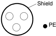
Symmetrical shielded motor cable must be used (figure below). Four-conductor system is allowed for mains cabling, but shielded symmetrical cable is recommended. To operate as a protective conductor, the shield conductivity must be at least 50 % of the conductivity of the phase lead.
Compared to a four-conductor system, the use of symmetrical shielded cable reduces electromagnetic emission of the whole drive system as well as motor bearing currents and wear.
The motor cable and its PE pigtail should be kept as short as possible in order to reduce electromagnetic emission as well as capacitive current.
3-2 ACA 6xx Sections and ACS/ACC 6x7 (132 to 3000 kW) Frequency Converters
Alternatives Power cable types that can be used with ACx 600 are represented below.
Recommended Symmetrical shielded cable: three phase conductors and a concentric or otherwise symmetrically constructed PE conductor, and a shield
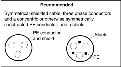
A separate PE conductor is required if the conductivity of the cable shield is < 50 % of the conductivity of the phase conductor.
A four-conductor system: three phase conductors and a protective conductor. Not allowed for motor cable.
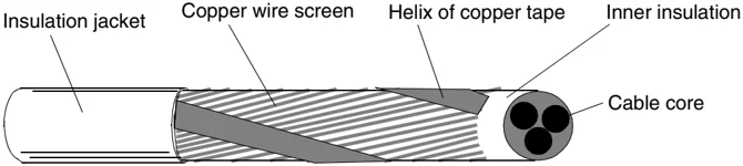
Motor Cable Shield To effectively suppress radiated and conducted radio-frequency emissions, the shield conductivity must be at least 1/10 of the phase conductor conductivity. The effectiveness of the shield can be evaluated e.g. on the basis of the shield inductance, which must be low and only slightly dependent on the frequency. These requirements are easily met with a copper or aluminium shield/armour. The minimum requirement of the motor cable shield of the ACx 600 is shown below. It consists of a concentric layer of copper wires with an open helix of copper tape. The better and tighter the shield, the lower the emission level and the bearing currents.
ACA 6xx Sections and ACS/ACC 6x7 (132 to 3000 kW) Frequency Converters 3-3

Chapter 3 – Electrical Installation
Control Cable Selection
All control cables must be shielded. As a general rule, the control signal cable shield should be earthed directly in the ACx 600. The other end of the shield should be left unconnected or earthed indirectly via some nanofarad high-frequency, high-voltage capacitor (e.g. 3.3 nF / 3000 V). The screen can also be earthed directly at both ends if they are in the same earth line with no significant voltage drop between the end points.
Twisting the signal wire with its return wire reduces disturbances caused by inductive coupling. Pairs should be twisted as close to terminals as possible.
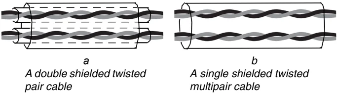
A double shielded twisted pair cable (Figure a, e.g. JAMAK by NK Cables, Finland) must be used for analogue signals and the pulse encoder signals. Employ one individually shielded pair for each signal. Do not use common return for different analogue signals.
A double shielded cable is the best alternative for low voltage digital signals but single shielded twisted multipair cable (Figure b) is also usable.
a A double shielded twisted pair cable
b A single shielded twisted multipair cable
The analogue and digital signals should be run in separate, screened cables.
Relay-controlled signals, providing their voltage does not exceed 48 V, can be run in the same cables as digital input signals. It is recommended that the relay-controlled signals be run as twisted pairs.
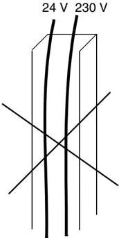
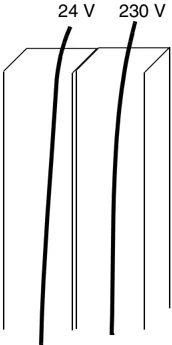
Never mix 24 VDC and 115 / 230 VAC signals in the same cable.
Co-axial Cable
Recommendations for use with ACS 600 MultiDrive Application Controller:
• 75 \Omega type
• RG59 cable with diameter 7 mm or RG11 cable 11 mm
• The maximum cable length is 300 m
Optical Cable When cutting the cable, for example with cutters, the optical cable ends become rough and may cause damping in the cable; the cable ends, therefore, should be ground with fine sand-paper.
Relay Cable The cable type with braided metallic screen (e.g. ÖLFLEX LAPPKABEL, Germany) has been tested and approved by ABB Industry.
Control Panel Cable In remote use, the cable connecting the Control Panel to the ACx 600 must not exceed 3 metres. The cable type tested and approved by ABB Industry is used in Control Panel option kits.
ACA 6xx Sections and ACS/ACC 6x7 (132 to 3000 kW) Frequency Converters
I nsulation Checks
Every ACS 600 MultiDrive system and ACx 6x7 unit (132 to 3000 kW) has been tested for insulation between main circuit and cabinet (2500 V rms 50 Hz for 1 minute) at the factory. Therefore there is no need to check the insulation of the unit again. When checking the insulation of the assembly, proceed in the following manner:
WARNING! Insulation checks must be performed before connecting the ACx 600 to the mains. Before proceeding with the insulation resistance measurements make sure that the ACx 600 is disconnected from the mains.
Motor and Motor Cable
R ≥ 1 M\Omega
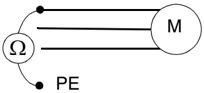
- Check that the motor cable is disconnected from the ACx 600 output terminals U2, V2 and W2.
- Measure the insulation resistances of motor cable and the motor between each phase and Protective Earth using a measuring voltage of 1 kV d.c. The insulation resistance must be higher than 1 M\Omega.
DC Busbars
- Measure the resistance between each DC busbar and Protective Earth with a multimeter.
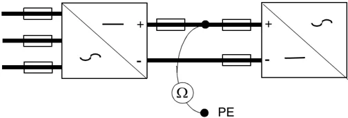
R ≥ 100 k\Omega
3-6 ACA 6xx Sections and ACS/ACC 6x7 (132 to 3000 kW) Frequency Converters
- Measure the resistance between the DC busbars with a multimeter.
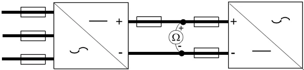
R = ∞ or rises gradually depending on the multimeter type
Fuses
Fuses are needed to protect the supply section and the inverter of the ACx 600 in case of an internal short circuit. The ACS 600 MultiDrive and the ACx 6x7 are equipped with internal input fuses introduced in Appendix A – Technical Data (located in the Safety and Product Information manual for ACS 600 MultiDrive). If a fuse is blown, it must be replaced with a similar ultrarapid fuse.
Internal Fuses
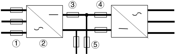
The fuse types used with different supply sections of ACS 600 MultiDrive frequency converters and ACx 6x7 units from 630 to 3000 kW are listed below.
| Fuse Type | Supply Section | |
|---|---|---|
| 1 | Supply AC fuses | B1, B2, B3 |
| 2 | Branch fuses. Each semiconductor of the rectifier bridge is protected with a fuse. | B4, B5 |
| 3 | Supply DC fuses | Thyristor Supply: B1, B2, B3 |
| 4 | Drive unit DC fuses. These fuses are in all ACS 600 MultiDrive units and in parallel connected ACx 6x7 units. | |
| 5 | Braking section DC fuses |
ACA 6xx Sections and ACS/ACC 6x7 (132 to 3000 kW) Frequency Converters 3-7
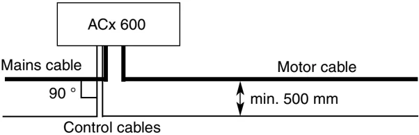
Cable Routing The motor cable should be installed away from other cable routes. Motor cables of several frequency converters can be run in parallel installed next to each other. It is recommended that the motor cable, mains cable and control cables be installed on separate trays (minimum distance 500 mm). Long parallel runs of motor cable with other cables should be avoided in order to decrease electromagnetic interference caused by the rapid changes in the frequency converter output voltage.
Where control cables must cross power cables make sure they are arranged at an angle as near to 90 degrees as possible. Extra cables should not be run through the ACx 600.
The cable trays shall have good electrical bonding to each other and to the earthing eletrodes. Aluminium tray systems can be used to improve local equalizing of potential.
Below is a diagram of cable routing.
Control Cable Ducts
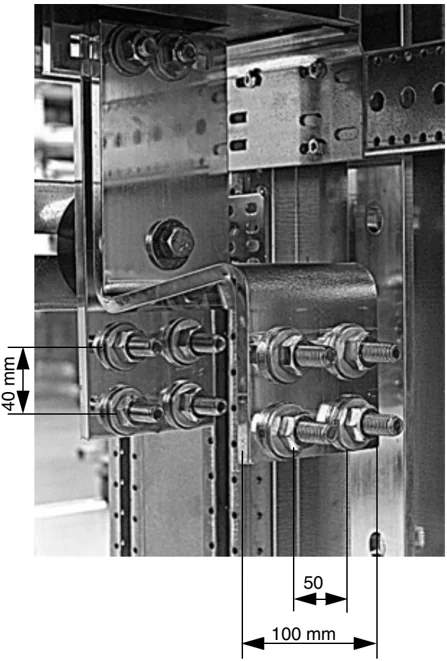
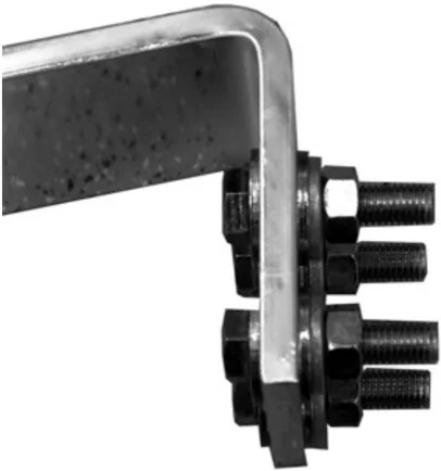
Power Cable Busbars A view of power cable busbars of large ACx 600 units is shown below. If necessary, the same screw can be used for connecting two cable lugs (on both sides of the busbar). Cable lugs with one or two holes can be used. Always use a torque wrench for tightening the busbar connections. Note: In inverter modules R6i and R7i, only one cable lug can be connected to a busbar screw.
ACA 6xx Sections and ACS/ACC 6x7 (132 to 3000 kW) Frequency Converters 3-9
Mains Cable Connection
This section describes the mains cable connections of the ACx 600. The following Motor Cable Connection section provides some basic instructions for the routing and mechanical connection of cables. The mechanical cable connections are basically the same, whether for the incoming supply or an inverter; different are the cabinet dimensions and the location of the terminals for the cables. The cabling direction may also vary (top or bottom).
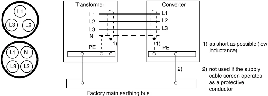
The N conductor is not normally used with ACx 600 frequency converters although it is visible in the following diagrams.
Low Power Supply A low current (< 300 A) cable connection when one cable is sufficient is represented below.
3-10 ACA 6xx Sections and ACS/ACC 6x7 (132 to 3000 kW) Frequency Converters
High Power Supply
Busbar connection A high current (> 300 A) busbar connection is represented below.
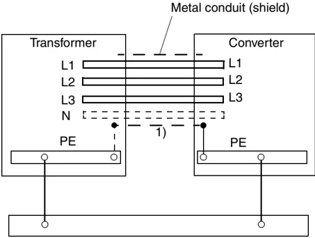
Note: The paint should be removed to allow a good connection to the cabinet frames throughout the whole perimeter of the metal conduit (or a bus duct). The metal conduit (or the bus duct metal) should be electrically continuous throughout its complete length.
Cable Bus System The connection of a high current (> 300 A) cable bus system that consists of several cables is represented below. In this system, less conductor material is needed due to better cooling of separate conductors.
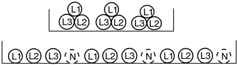
It is recommended to arrange the cables as shown alongside to achieve a current distribution as accurate as possible. Air between cables is required for cooling.
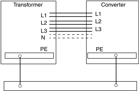
Note: Current derating of the cables is required when installing the cables in a cable tray. This derating factor must be taken into account as per the local electrical safety codes.
ACA 6xx Sections and ACS/ACC 6x7 (132 to 3000 kW) Frequency Converters 3-11
Single-core Cables with Concentric Protective Shields
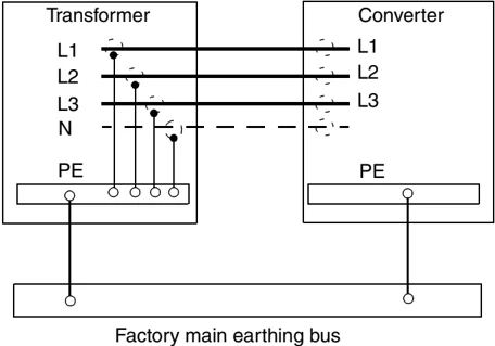
When single-core cables equipped with concentric protective shields (metal) are used, the phase current will induce voltage to the cable shield. If the shields are connected to each other at both ends of the cable, current will flow in the cable shield. In order to prevent this and to ensure personal safety, the cable shield must be connected only to PE at the transformer side and insulated on the converter side. The connection is represented below.
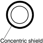
Concentric shield
Transformer L1 L2 L3 N PE
Converter L1 L2 L3 PE
Factory main earthing bus
3-12 ACA 6xx Sections and ACS/ACC 6x7 (132 to 3000 kW) Frequency Converters
Motor Cable Connection
Motor cable connections for different cable types are represented below. For minimum radio frequency interference (RFI) at the motor end, earth the cable screen 360 degrees at the lead-through or earth the cable by twisting the screen (flattened width ≥ 1/5 \cdot length).
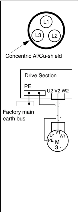
A separate PE conductor system is used only if local safety regulations do not allow earthing of the ACx 600 and the motor merely through the cable screen. This solution increases motor bearing currents compared to symmetrical shielded cable, thus causing extra wear.
ACA 6xx Sections and ACS/ACC 6x7 (132 to 3000 kW) Frequency Converters
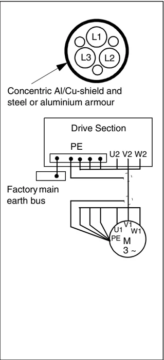
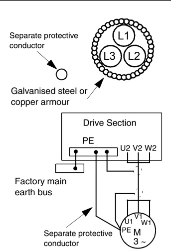
High Power Applications Motor cable connections with parallel symmetrical cables are represented below.
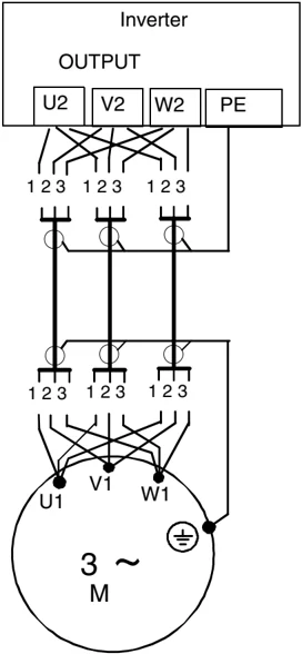
Parallel Connected Inverters Motor cable connections with parallel connected inverters are presented below. Parallel connected cables are drawn as single cables to simplify the drawings.
Requirements for parallel connected cables and cables for motors with two separate windings are given as follows:
- The maximum allowed difference in cable length is 5 % i.e. the length of the longest cable divided by that of the shortest cable must be less than or equal to 1.05: l_max/l_min ≤ 1.05.
- Cables must be of the same type and have equal cross-sectional areas.
3-14 ACA 6xx Sections and ACS/ACC 6x7 (132 to 3000 kW) Frequency Converters