Haas Technical Publications
Manual_Archive_Cover_Page Rev A June 6, 2013
HAAS SERVICE AND OPERATOR MANUAL ARCHIVE
Lathe Operators Manual 96-8700U 9 RevU English June 2008
- This content is for illustrative purposes.
- Historic machine Service Manuals are posted here to provide information for Haas machine owners.
- Publications are intended for use only with machines built at the time of original publication.
- As machine designs change the content of these publications can become obsolete.
- You should not do mechanical or electrical machine repairs or service procedures unless you are qualified and knowledgeable about the processes.
- Only authorized personnel with the proper training and certification should do many repair procedures.
WARNING: Some mechanical and electrical service procedures can be extremely dangerous or life-threatening. Know your skill level and abilities.
All information herein is provided as a courtesy for Haas machine owners for reference and illustrative purposes only. Haas Automation cannot be held responsible for repairs you perform. Only those services and repairs that are provided by authorized Haas Factory Outlet distributors are guaranteed.
Only an authorized Haas Factory Outlet distributor should service or repair a Haas machine that is protected by the original factory warranty. Servicing by any other party automatically voids the factory warranty.

HAAS SAFETY PROCEDURES
THINK SAFETY!
DON'T GET CAUGHT UP IN YOUR WORK
All turning machines contain hazards from rotating parts, belts and pulleys, high voltage electricity, noise, and compressed air. When using CNC machines and their components, basic safety precautions must always be followed to reduce the risk of personal injury and mechanical damage.
Important – This machine is to be operated only by trained personnel in accordance with the Operator’s manual, safety decals, safety procedures and instructions for safe machine operation.
Safety Contents
- USES AND GUIDELINES FOR PROPER MACHINE OPERATION ........ 4
- MODIFICATIONS TO THE MACHINE ........ 4
- SAFETY PLACARDS ........ 4
- MILL WARNING DECALS ........ 6
- LATHE WARNING DECALS ........ 7
- DECLARATION OF WARNINGS, CAUTIONS, AND NOTES ........ 7
General Product Use Specifications and Limits
Environmental (Indoor use only)*
| Minimum | Maximum | |
|---|---|---|
| Operating Temperature | 41° F (5° C) | 122° F (50° C) |
| Storage Temperature | -4° F (-20° C) | 158° F (70° C) |
| Ambient Humidity | 20% relative, non-condensing | 90% relative, non-condensing |
| Altitude | Sea Level | 6000 ft. (1829 m) |
Noise
| Minimum | Maximum** | |
|---|---|---|
| Emitted from all areas of machine during use at a typical operator’s position | Greater than 70 dB | Greater than 85dB |
*Do not operate the machine in explosive atmospheres (explosive vapors and / or particulate matter)
**Take precautions to prevent hearing damage from machine/machining noise. Wear ear protection, alter cutting application (tooling, spindle speed, axis feed, fixturing, programmed path) to reduce noise, and / or restrict access to machine area during cutting.
96-8700 rev U June 2008 Safety 1

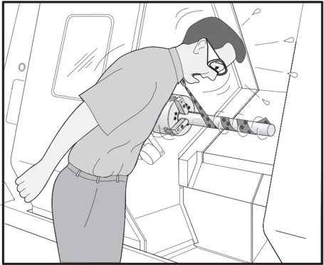
READ BEFORE OPERATING THIS MACHINE:
◆ Only authorized personnel should work on this machine. Untrained personnel present a hazard to themselves and the machine, and improper operation will void the warranty.
◆ Check for damaged parts and tools before operating the machine. Any part or tool that is damaged should be properly repaired or replaced by authorized personnel. Do not operate the machine if any component does not appear to be functioning correctly. Contact your shop supervisor.
◆ Use appropriate eye and ear protection while operating the machine. ANSI approved impact safety goggles and OSHA approved ear protection are recommended to reduce the risks of sight damage and hearing loss.
◆ Do not operate the machine unless the doors are closed and the door interlocks are functioning properly. Rotating cutting tools can cause severe injury. When a program is running, the tool turret can move rapidly at any time in any direction.
◆ The Emergency Stop button (also known as an Emergency Power Off button) is the large, circular red switch located on the Control Panel. Pressing the Emergency Stop button will instantly stop all motion of the machine, the servo motors, the tool changer, and the coolant pump. Use the Emergency Stop button only in emergencies to avoid crashing the machine.
◆ The electrical panel should be closed and the key and latches on the control cabinet should be secured at all times except during installation and service. At those times, only qualified electricians should have access to the panel. When the main circuit breaker is on, there is high voltage throughout the electrical panel (including the circuit boards and logic circuits) and some components operate at high temperatures. Therefore, extreme caution is required. Once the machine is installed, the control cabinet must be locked and the key available only to qualified service personnel.
◆ Consult your local safety codes and regulations before operating the machine. Contact you dealer anytime safety issues need to be addressed.
◆ DO NOT modify or alter this equipment in any way. If modifications are necessary, all such requests must be handled by Haas Automation, Inc. Any modification or alteration of any Haas Milling or Turning Center could lead to personal injury and/or mechanical damage and will void your warranty.
◆ It is the shop owner's responsibility to make sure that everyone who is involved in installing and operating the machine is thoroughly acquainted with the installation, operation, and safety instructions provided with the machine BEFORE they perform any actual work. The ultimate responsibility for safety rests with the shop owner and the individuals who work with the machine.
OBSERVE ALL OF THE WARNINGS AND CAUTIONS BELOW:
- Do not operate with the door open.
- Do not operate without proper training.
- Always wear safety goggles.
- The machine is automatically controlled and may start at any time.
- Improperly or inadequately clamped parts may be ejected with deadly force.
- Do not exceed rated chuck rpm.
- Higher rpm reduces chuck clamping force.
- Unsupported bar stock must not extend past draw tube end.
- Chucks must be greased weekly and regularly serviced.
- Chuck jaws must not protrude beyond the diameter of the chuck.
- Do not machine parts larger than the chuck.
- Follow all of the warnings of the chuck manufacturer regarding the chuck and work holding procedures.
- Hydraulic pressure must be set correctly to securely hold the work piece without distortion.
- The electrical power must meet the specifications in this manual. Attempting to run the machine from any other source can cause severe damage and will void the warranty.
- DO NOT press POWER UP/RESTART on the control panel until after the installation is complete.
- DO NOT attempt to operate the machine before all of the installation instructions have been completed.
- NEVER service the machine with the power connected.
- Improperly clamped parts at high velocity may puncture the safety door. Reduced rpm is required to protect the operator when performing dangerous operations (e.g. turning oversized or marginally clamped parts). Turning oversized or marginally clamped parts is not safe.
- Windows must be replaced if damaged or severely scratched - Replace damaged windows immediately.
- Do not process toxic or flammable material. Deadly fumes can be present. Consult material manufacturer for safe handling of material by-products before processing.
Unattended Operation
Fully enclosed Haas CNC machines are designed to operate unattended; however, your machining process may not be safe to operate unmonitored.
As it is the shop owner's responsibility to set up the machines safely and use best practice machining techniques, it is also their responsibility to manage the progress of these methods. The machining process must be monitored to prevent damage if a hazardous condition occurs.
For example, if there is the risk of fire due to the material machined, then an appropriate fire suppression system must be installed to reduce the risk of harm to personnel, equipment and the building. A suitable specialist must be contacted to install monitoring tools before machines are allowed to run unattended.
It is especially important to select monitoring equipment that can immediately perform an appropriate action without human intervention to prevent an accident, should a problem be detected.
96-8700 rev U June 2008 Safety 3
USES AND GUIDELINES FOR PROPER MACHINE OPERATION
All turning machines contain hazards from rotating cutting tools, belts and pulleys, high voltage electricity, noise, and compressed air. When using turning machines and their components, basic safety precautions should always be followed to reduce the risk of personal injury and mechanical damage. READ ALL APPROPRIATE WARNINGS, CAUTIONS, AND INSTRUCTIONS BEFORE OPERATING THIS MACHINE.
MODIFICATIONS TO THE MACHINE
DO NOT modify or alter this equipment in any way. If modifications are necessary, all such requests must be handled by Haas Automation, Inc. Any modification or alteration of any Haas machining center could lead to personal injury and/or mechanical damage and will void your warranty.
SAFETY DECALS
To help ensure that CNC tool dangers are quickly communicated and understood, hazard symbol decals are placed on Haas Machines in locations where hazards exist. If decals become damaged or worn, or if additional decals are needed to emphasize a particular safety point, contact your dealer or the Haas factory. Never allow anyone to alter or remove any safety decal or symbol.
Each hazard is defined and explained on the general safety decal, located at the front of the machine. Particular locations of hazards are marked with warning symbols. Review and understand the four parts of each safety warning, explained below, and familiarize yourself with the symbols on the following pages.
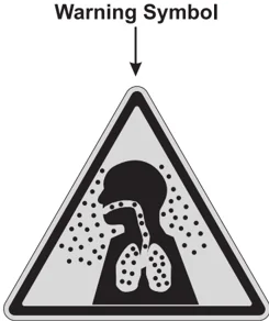
Warning Symbol - Identifies the potential hazard and reinforces the word message. Word Message - Clarifies or reinforces the intent of the warning symbol. A: Hazard. B: Consequence if warning is ignored. C: Action to prevent injury. Also refer to Action Symbol.
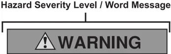
Hazard Severity Level - Color-coded to indicate risk in ignoring a hazard. Red + "DANGER" = Hazard WILL cause death or serious injury if ignored. Orange + "WARNING" = Hazard COULD cause death or serious injury if ignored. Yellow + "CAUTION" = Hazard MAY cause minor to moderate injury if ignored. Blue + "NOTICE" = Indicates an action to prevent damage to the machine. Green + "INFORMATION" = Details about machine components.
Action Symbol: Indicates actions to prevent injury. Blue circles indicate mandatory actions to avoid harm, red circles with diagonal slashes indicate prohibited actions to avoid harm.
4 Safety 96-8700 rev U June 2008

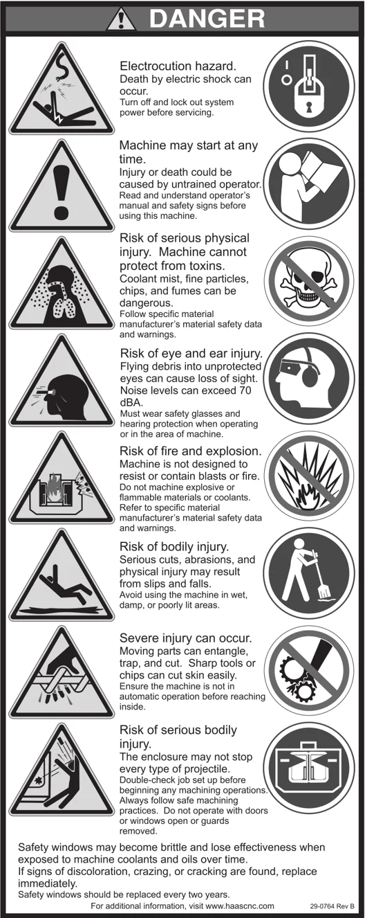
DANGER
Electrocution hazard. Death by electric shock can occur. Turn off and lock out system power before servicing.
Machine may start at any time. Injury or death could be caused by untrained operator. Read and understand operator's manual and safety signs before using this machine.
Risk of serious physical injury. Machine cannot protect from toxins. Coolant mist, fine particles, chips, and fumes can be dangerous. Follow specific material manufacturer's material safety data and warnings.
Risk of eye and ear injury. Flying debris into unprotected eyes can cause loss of sight. Noise levels can exceed 70 dBA. Must wear safety glasses and hearing protection when operating or in the area of machine.
Risk of fire and explosion. Machine is not designed to resist or contain blasts or fire. Do not machine explosive or flammable materials or coolants. Refer to specific material manufacturer's material safety data and warnings.
Risk of bodily injury. Serious cuts, abrasions, and physical injury may result from slips and falls. Avoid using the machine in wet, damp, or poorly lit areas.
Severe injury can occur. Moving parts can entangle, trap, and cut. Sharp tools or chips can cut skin easily. Ensure the machine is not in automatic operation before reaching inside.
Risk of serious bodily injury. The enclosure may not stop every type of projectile. Double-check job set up before beginning any machining operations. Always follow safe machining practices. Do not operate with doors or windows open or guards removed.
Safety windows may become brittle and lose effectiveness when exposed to machine coolants and oils over time. If signs of discoloration, crazing, or cracking are found, replace immediately. Safety windows should be replaced every two years.
For additional information, visit www.haascnc.com 29-0764 Rev B
MILL WARNING DECALS
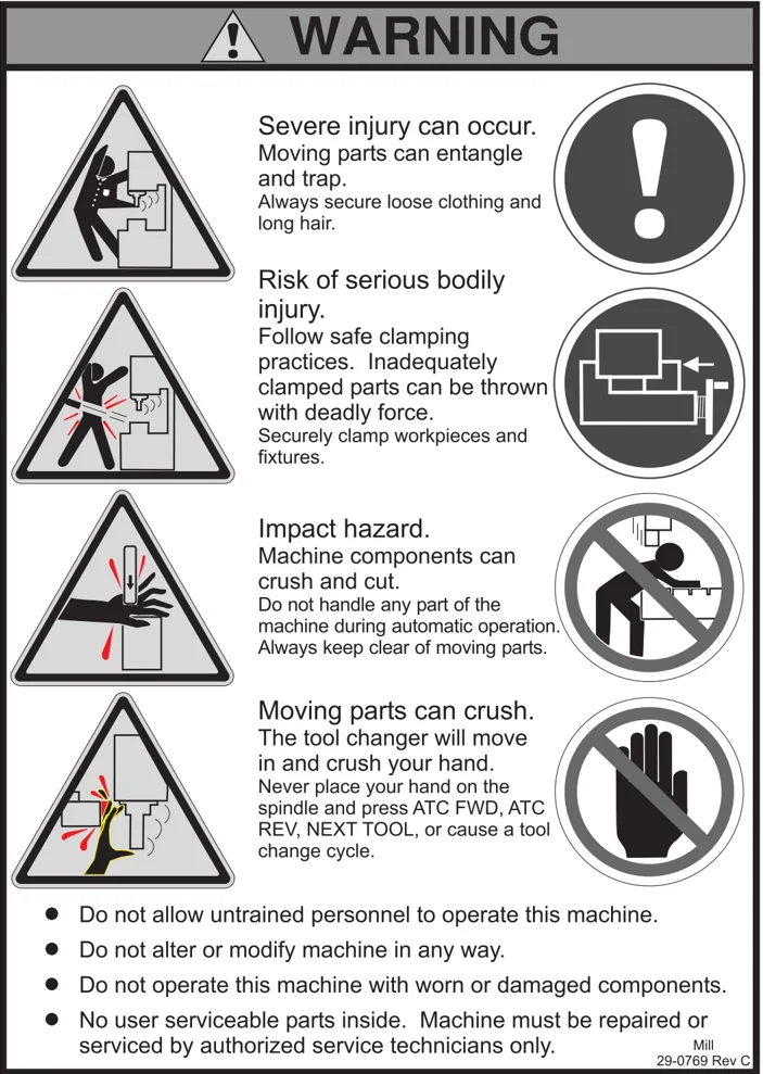
WARNING
Severe injury can occur. Moving parts can entangle and trap. Always secure loose clothing and long hair.
Risk of serious bodily injury. Follow safe clamping practices. Inadequately clamped parts can be thrown with deadly force. Securely clamp workpieces and fixtures.
Impact hazard. Machine components can crush and cut. Do not handle any part of the machine during automatic operation. Always keep clear of moving parts.
Moving parts can crush. The tool changer will move in and crush your hand. Never place your hand on the spindle and press ATC FWD, ATC REV, NEXT TOOL, or cause a tool change cycle.
- Do not allow untrained personnel to operate this machine.
- Do not alter or modify machine in any way.
- Do not operate this machine with worn or damaged components.
- No user serviceable parts inside. Machine must be repaired or serviced by authorized service technicians only.
Mill 29-0769 Rev C
6 Safety 96-8700 rev U June 2008
LATHE WARNING DECALS
WARNING
Severe injury can occur. Moving parts can entangle and trap. Always secure loose clothing and long hair.
Risk of serious bodily injury. Inadequately clamped parts can be thrown with deadly force. High RPM reduces chuck clamping force. Do not machine using an unsafe setup or exceed rated chuck RPM.
Moving parts can cut. Sharp tools can cut skin easily. Do not handle any part of the machine during automatic operation. Do not touch rotating work pieces.
Risk of serious bodily injury and impact hazard. Unsupported bar can whip with deadly results. Do not extend barstock past end of drawtube without adequate support. Do not apply excessive machining forces, doing so can dislodge the bar from support. Do not allow the carriage or tool to strike the steady rest or tailstock; the part may come loose. Do not over tighten steady rest.
- Do not allow untrained personnel to operate this machine.
- Restrict access to open frame lathes.
- Use steady rest or tailstock to support long bars and always follow safe machining practices.
- Do not alter or modify machine in any way.
- Do not operate this machine with worn or damaged components.
- Machine must be repaired or serviced by authorized technicians only.
Lathe 29-0765 Rev C
96-8700 rev U June 2008 Safety 7
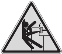

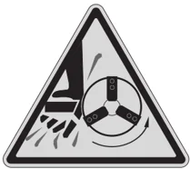
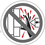
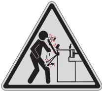
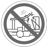
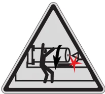
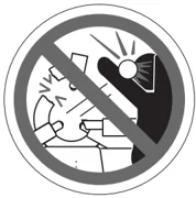
OTHER SAFETY DECALS
Other decals may be found on your machine, depending on the model and options installed:
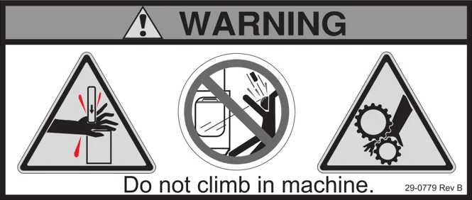
 WARNING
Do not climb in machine.
29-0779 Rev B
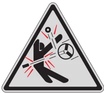
WARNING Risk of serious bodily injury. Parts can be ejected with lethal force. Do not over tighten steady rest. Always follow safe machining practices.
Risk of serious bodily injury. Machining forces will deflect the bar and can dislodge it from the tailstock support. Bar will whip and cause injuries. Do not apply excessive cutting loads to the workpiece. Always follow safe machining practices. 29-0611 Rev B
 WARNING
Adjustable Tailstock
Moving parts can cut and crush.
Tailstock moves automatically and has pinch points.
Press Emergency Stop button before changing tailstock attach position.
Refer to the tailstock section for further explanation.
8 Safety 96-8700 rev U June 2008
DANGER

No Step Risk of electrocution, bodily injury, or machine damage. Do not climb or stand on this area. 29-0746 Rev C
DECLARATION OF WARNINGS, CAUTIONS, AND NOTES
Throughout this manual, important and critical information is prefaced with the word "Warning", "Caution" and "Note" Warnings are used when there is an extreme danger to the operator and/or to the machine. Take all steps necessary to heed the warning given. Do not continue if you cannot follow the warning instructions. An example warning is:
WARNING! Never put hands between tool changer and spindle head.
Cautions are used when there is the potential for minor personal injury or mechanical damage, for example: CAUTION! Power down the machine before performing any maintenance tasks.
Notes give additional information to the operator about a particular step or procedure. This information should be taken into consideration by the operator as the step is performed to ensure there is no confusion, for example:
NOTE: If machine is equipped with the optional extended Z-clearance table, follow these guidelines: • Avoid extreme loads on the center of table or far end of table. The weight of the part should be distributed evenly over the table or one pad. • Flatness of part should be within 0.002".
96-8700 rev U June 2008 Safety 9
10
Safety
96-8700 rev U June 2008
INTRODUCTION
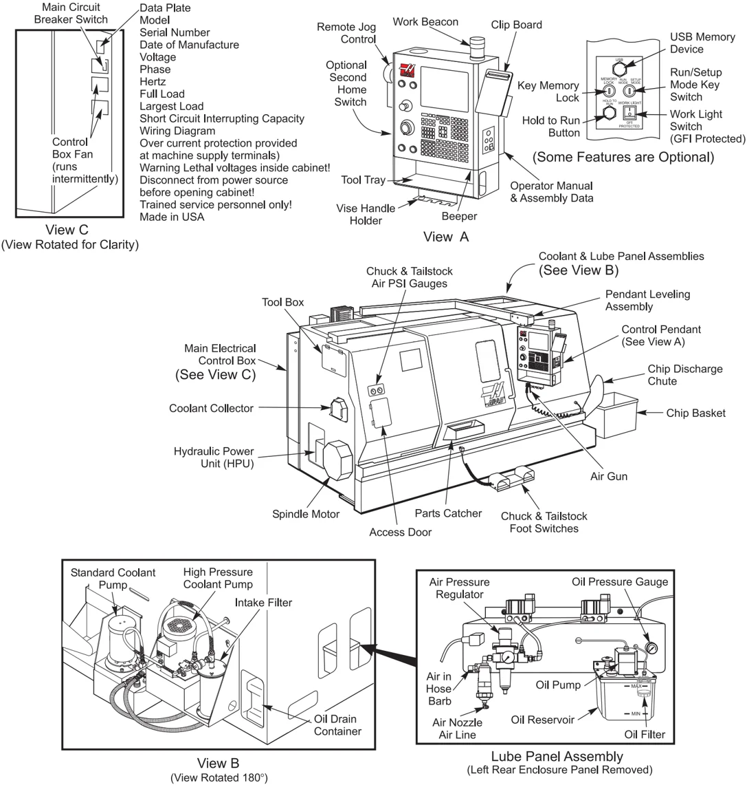
The following is a visual introduction to a Haas turning center. Some of the features shown will be highlighted in their appropriate sections.
View C (View Rotated for Clarity)
Main Circuit Breaker Switch Control Box Fan (runs intermittently)
Data Plate Model Serial Number Date of Manufacture Voltage Phase Hertz Full Load Largest Load Short Circuit Interrupting Capacity Wiring Diagram Over current protection provided at machine supply terminals) Warning Lethal voltages inside cabinet! Disconnect from power source before opening cabinet! Trained service personnel only! Made in USA
View A
Remote Jog Control Work Beacon Clip Board Optional Second Home Switch Tool Tray Vise Handle Holder Beeper Operator Manual & Assembly Data Key Memory Lock Hold to Run Button USB Memory Device Run/Setup Mode Key Switch Work Light Switch (GFI Protected) (Some Features are Optional)
Chuck & Tailstock Air PSI Gauges Tool Box Main Electrical Control Box (See View C) Coolant Collector Hydraulic Power Unit (HPU) Spindle Motor Access Door Parts Catcher Chuck & Tailstock Foot Switches Air Gun Chip Basket Chip Discharge Chute Pendant Leveling Assembly Control Pendant (See View A) Coolant & Lube Panel Assemblies (See View B)
View B (View Rotated 180°)
Standard Coolant Pump High Pressure Coolant Pump Intake Filter Oil Drain Container
Lube Panel Assembly (Left Rear Enclosure Panel Removed)
Air Pressure Regulator Oil Pressure Gauge Air in Hose Barb Air Nozzle Air Line Oil Pump Oil Reservoir Oil Filter
96-8700 rev U June 2008 Operation 11
 Tool Turret
Tailstock
(Optional)
Hydraulic
Power Unit
(HPU)
Steadyrest Support
(Optional)
Parts Catcher
(Optional)
Spindle Motor
 Live Tooling
(Optional)
Chuck
Tool Probe
(Optional)
C-Axis Assembly
(Optional)
Parts Catcher
(Optional)
Sub-spindle Assembly
(TL-15 & TL-25 only)
12 Operation 96-8700 rev U June 2008
CONTROL DISPLAY AND MODES
The control display is organized into panes that vary depending on the current control mode, and on what display keys are used. The following illustration shows the basic display layout:
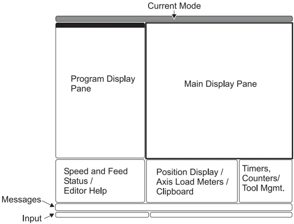
Interaction with data can be carried out only within the currently active pane. Only one pane is active at any given time, and it is indicated with a white background. For example, to work with the Tool Offsets table, you must first make the table active by pressing the Offset key until it displays with a white background. Then you can make changes to the data. Changing the active pane within a control mode is typically done with the display keys.
Control functions are organized into three modes: Setup, Edit, and Operation. Each mode provides all of the necessary information to perform tasks that fall under the mode, organized to fit in one screen. For example, Setup mode displays both the work and tool offset tables, and position information. Edit mode provides two program editing panes and access to the VQCP and IPS/WIPS systems (if installed).
Access modes using the mode keys as follows:
Setup: ZERO RET, HAND JOG keys. Provides all control features for machine setup.
Edit: EDIT, MDI/DNC, LIST PROG keys. Provides all program editing, management, and transfer functions.
Operation: MEM key. Provides all control features necessary to make a part.
The current mode is shown in the title bar at the top of the display.
Note that functions from other modes can still be accessed from within the active mode by using the display keys. For example, while in Operation mode, pressing OFFSET will display the offsets tables as the active pane; toggle the offset display using the OFFSET key. pressing PROGRM CONVRS in most modes will shift to the edit pane for the current active program.
NAVIGATING TABBED MENUS
Tabbed menus are used in several control functions, such as Parameters, Settings, Help, List Prog, and IPS. To navigate these menus, use the arrow keys to select a tab, then press Enter to open the tab. If the selected tab contains sub-tabs, use the arrow keys and Enter to select the appropriate one.
To go up one tab level, press Cancel.
PENDANT KEYBOARD INTRODUCTION
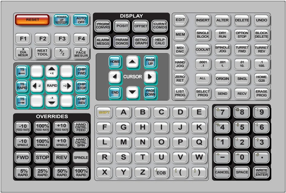
The keyboard is broken up into eight sections: Function Keys, Jog Keys, Override Keys, Display Keys, Cursor Keys, Alpha Keys, Mode Keys and Number Keys. In addition there are miscellaneous keys and features located on the pendant and keyboard which are described briefly.
Power On- Turns the machine on. Power Off- Turns the machine off. Spindle Load Meter - Displays the spindle load, in percent. Emergency Stop - This stops all axes motion, stops the spindle, turret, and turns off the coolant pump. Jog Handle - This is used to jog all axes. Can also be used to scroll through program code or menu items while editing. Cycle Start - Starts a program. This button is also used to start a program in Graphics mode. Feed Hold - Will stop all axis motion. Note: Spindle will continue to turn during cutting. Reset - Will stop the machine (axes, spindle, coolant pump, and turret are stopped). This is not a recommended method to stop the machine, as it may be difficult to continue from that point. Power Up/Restart - When this key is pressed, the axes will return to the machine zero position and a tool change may occur. See Setting 81 in the Settings chapter for more information. This will not work for toolroom lathes, subspindle lathes, or automatic parts loader (APL). Auto Off - Automatically positions axes to machine zero and prepares the machine for power down.
14 Operation 96-8700 rev U June 2008
Memory Lock Key Switch - This switch prevent the operator from editing programs and from altering settings when turned to the locked position. The following describes the hierarchy of locks: Key switch locks Settings and all programs. Setting 7 locks parameters. Setting 8 locks all programs. Setting 23 locks 9xxx programs. Setting 119 locks offsets. Setting 120 locks macro variables.
Second Home Button - This button will rapid all axes to the coordinates specified in work Offset G154 P20. This feature will work in any mode except DNC.
Work Light Switch - This switch will turn on the work light inside of the machine.
Keyboard Beeper - Located at the top of the parts tray. The volume can be adjusted by turning the cover.
FUNCTION KEYS
F1- F4 Keys – These buttons have different functions depending upon which mode of operation you are in. For example, F1-F4 will cause a different action in Editing mode, than Program mode, than Offset mode. See the specific mode section for further descriptions and examples.
X Dia Mesur (X Diameter Measure) – Used to record X-axis tool shift offsets on the offset page during part setup.
Next Tool – Used to select the next tool from the turret (usually used during part setup).
X/Z – Used to toggle between X-axis and Z-axis jog modes during part setup.
Z Face Mesur ( Z Face Measure) – Used to record Z-axis tool shift offsets on the offset page during part setup.
JOG KEYS
Chip FWD (Chip Auger Forward) - Starts optional chip auger in the “Forward” direction, moving chips out of the machine.
Chip Stop (Chip Auger Stop) - Stops auger movement.
Chip REV (Chip Auger Reverse) - Starts the optional chip auger in the “Reverse” direction, which is useful in clearing jams and debris from auger.
X/-X and Z/-Z (axis keys) - Allows the operator to manually jog axis by holding down the individual button or pressing the desired axes and using the jog handle.
Rapid - When pressed simultaneously with one of the above keys (X+, X-, Z+, Z-), that axis will move in the selected direction at maximum jog speed.
<- TS – Pressing this key moves the tailstock towards the spindle.
TS Rapid – Increases the speed of the tailstock when pressed simultaneously with one of the other tailstock keys.
-> TS – Pressing this key moves the tailstock away from the spindle.
XZ (2-Axis) Jogging The lathe X and Z axes can be jogged simultaneously using the X and Z jog buttons. Holding any combination of +/-X and +/-Z jog buttons will cause two axis jogging. Releasing both jog buttons will result in the control reverting to X-axis jog mode. If only a single button is released, the control will continue jogging the single axis of the button still held. Note: Normal tailstock restricted zone rules are active while engaged in XZ jogging.
OVERRIDE KEYS
These keys give the user the ability to override the speed of non-cutting (rapid) axes motion, programmed feeds and spindle speeds.
-10 - Decreases current feedrate by 10%. 100% - Sets control overriden feedrate to programmed feedrate. +10 - Increases current feedrate by 10%. -10 - Decreases current spindle speed by 10%. 100% - Sets overridden spindle speed to programmed speed. +10 - Increases current spindle speed by 10%.
Hand Cntrl. Feed (Handle Control Feedrate) - Pressing this button allows the jog handle to be used to control the feedrate in ±1% increments.
Hand Cntrl Spin (Handle Control Spindle) - Pressing this button allows the jog handle to be used to control spindle speed in ±1% increments.
FWD - Starts the spindle in the Forward (clockwise) direction. This button is disabled on CE (export) machines.
REV - Starts the spindle in the Reverse (counterclockwise) direction. This button is disabled on CE (export) machines.
The spindle can be started or stopped with the Fwd or Rev buttons any time the machine is at a Single Block stop or the Feed Hold button has been pressed. When the program is restarted with Cycle Start, the spindle will be turned back on to the previously defined speed.
STOP - Stops the spindle.
5% / 25% / 50% / 100% Rapid - Limits machine rapids to the value on the key. The 100% Rapid button allows maximum rapid.
Override Usage
The feedrate can be varied from 0% to 999% of the programmed value while in operation. This is done with the feedrate +10%, -10% and 100% buttons. The feedrate override is ineffective during tapping cycles. Feedrate override does not change the speed of any auxiliary axes. During manual jogging, the feedrate override will adjust the rates selected from the keypad. This allows for fine control of the jog speed.
The spindle speed can also be varied, from 0% to 999%, using the spindle overrides. It is also ineffective for tapping cycles. In the Single Block mode, the spindle may be stopped. It will automatically start up upon continuing the program with the Cycle Start button.
By pressing the Handle Control Feedrate key, the jog handle can be used to control feedrate from in ±1% increments.
Rapid moves (G00) may be limited to 5%, 25%, or 50% of maximum using the keypad. If the 100% rapid is too fast, it may be set to 50% of maximum by Setting 10.
In the Settings page, it is possible to disable the override keys so that the operator cannot select them. These are Settings 19, 20 and 21.
The Feed Hold button acts as an override button as it sets the rapid and feed rates to zero when it is pressed. The Cycle Start button must be pressed to proceed after a Feed Hold. The door switch on the enclosure also has a similar result but will display "Door Hold" when the door is opened. When the door is closed, the control will be in Feed Hold and Cycle Start must be pressed to continue. Door Hold and Feed Hold do not stop any auxiliary axes.
The operator can override the coolant setting by pressing the Coolnt button. The pump will remain either on or off until the next M-code or operator action (see Setting 32).
Overrides can be reset to defaults with an M06, M30 and/or pressing RESET (See Settings 83, 87,88).
DISPLAY KEYS
Display keys provide access to the machine displays, operational information and help pages. They are often used to switch active panes within a function mode. Some of these keys will display additional screens when pressed more than once.
Prgrm/Convrs - Selects the active program pane in most modes. In EDIT:MDI mode, press to access VQC and IPS (if installed).
Posit (Position) - Selects the positions pane, located in the lower center of most screens. Displays the current axis positions. Toggle between relative positions by pressing the POSIT key. To filter the axes displayed in the pane, type the letter for each axis you want to display and press WRITE/ENTER. Each axis position is displayed in the order you indicate.
Offset - Press to toggle between the two offsets tables. Select the Tool Offsets table to display and edit tool length geometry, radius offsets, wear offsets, and coolant position. Select the Work Offsets table to display and edit the G-code specified work offset locations used in programs.
Curnt Comds (Current Commands) - Press PAGE UP / PAGE DOWN to cycle through menus for Maintenance, Tool Life, Tool Load, Advanced Tool Management (ATM), Barfeeder, System Variables, azClock settings and timer / counter settings.
Alarm / Mesgs (Alarms / Messages) - Displays the alarm viewer and message screens. There are three alarm screens, the first shows the currently active alarms (first press of the Alarm/Mesgs button). Press the Right Arrow key to view Alarm History. Use the Up and Down Arrow keys to scroll through alarm history entries, and press F2 to write to a disk.
Pressing Right Arrow again switches to the Alarm Viewer screen. This screen shows one alarm at a time with its description. The default will be the last alarm in the alarm history. You can then scroll through the alarms by pressing the Up and Down Arrow buttons. You can also enter an alarm number and press Enter or the Up/Down arrow keys to display the alarm name and description.
Pressing Alarm/mesgs a second time will display a page for user messages and notes. Use the keypad to enter messages for other operators/programmers or write notes for a current project. If there is a message, it will display every time the machine is powered on, until it is erased. See Message section for more details.
Param / Dgnos (Parameters / Diagnostics) - Displays parameters that define the machine's operation. Parameters are organized by category in a tabbed menu, or to find a known parameter, type in the number and press the up or down arrow. Parameters are set at the factory and should not be modified except by authorized Haas personnel.
A second press of the Param / Dgnos key will display the first page of diagnostic data. This information is mainly used for troubleshooting by a certified Haas service technician. The first page of diagnostic data is discrete inputs and outputs. Pressing Page Down will display additional pages of diagnostic data.
Setng / Graph (Settings / Graphics) - Displays and allows changing of user settings. Like Parameters, Settings are organized by category in a tabbed menu. To find a known setting, type in the number and press the up or down arrow.
Pressing the Setng / Graph key a second time enables Graphics mode. In Graphics mode, you can view the generated tool path of the program and, if necessary, debug the program before running it (See Graphics Mode in the Operation section)
Help / Calc (Help / Calculator) - Displays help topics in a tabbed menu. Available help includes brief descriptions of G and M codes, definitions of control features, troubleshooting and maintenance issues. The help menu also includes several calculators.
Pressing the HELP/CALC key within some modes will call a pop-up help window. Use this window to access help topics relevant to the current mode, and also to execute certain functions as noted in the menu. To access the tabbed menu described above from a pop-up help window, press HELP/CALC a second time.
CURSOR KEYS
Cursor Keys give the user the ability to move to various screens and fields in the control and are used in the editing of CNC programs.
Home - This button will move the cursor to the top-most item on the screen; in editing, this is the top left block of the program.
Up/Down Arrows - moves up/down one item, block or field.
Page Up/Down - Used to change displays or move up/down one page when viewing a program.
Left Arrow - Used to select individually editable items when viewing a program; moves cursor to the left. It is used to scroll through setting selections and moves the zoom window left when in graphics mode.
Right Arrow - Used to select individually editable items when viewing a program; moves cursor to the right. It is used to scroll through setting selections and moves the zoom window right when in graphics mode.
End - This button generally moves the cursor to the bottom-most item on the screen. In editing, this is the last block of the program.
ALPHA KEYS
The alpha keys allow the user to enter the letters of the alphabet along with some special characters. Some of the special characters are entered by first pressing the "Shift" key.
Shift - The shift key provides access to additional characters on the keyboard. The additional characters are seen in the upper left of some of the alpha and number keys. Pressing Shift and then the character will enter that character on the data entry line. When entering text, Upper Case is the default; to enter lower case characters, press and hold the Shift key.
When a control has a fifth axis installed, the B-axis is selected for jogging by pressing "B" and then Handle Jog.
EOB - This is the End-Of-Block character. It is displayed as a semicolon (;) on the screen and it signifies the end of a program line.
( ) - Parentheses are used to separate CNC program commands from user text comments. They must always be entered as a pair. Note: Any time an invalid line of code is received through the RS-232 port while receiving a program, it is added to the program between parenthesis.
/ - The right slash is used in the Block Delete feature and in Macro expressions. If this symbol is the first symbol in a block and a Block Delete is enabled, then that block is ignored at run time. The symbol is also used for division (divide by) in macro expressions (see the Macro section).
[ ] - Square brackets are used in macro functions. Macros are an optional software feature (see the Macro section).
MODE KEYS
Mode keys change the operational state of the CNC machine tool. Once a mode button is pressed, the buttons in the same row are made available to the user. The current mode is always displayed on the top line just to the right of the current display.
Edit- Selects edit mode. This mode is used to edit programs in the control's memory. Edit mode provides two editing panes: one for the currently active program, and another for background editing. Switch between the two panes by pressing the EDIT key. Note: While using this mode in an active program, press F1 to access help pop-up menus.
Insert - Pressing this button will enter commands into the program at the cursor. This button will also insert the text from the clipboard to the current cursor location, and is also used to copy blocks of code in a program.
Alter - Pressing this button will change the highlighted command or text to the newly entered commands or text. This button will also change the highlighted variables to the text stored in the clipboard, or move a selected block to another location.
Delete - Deletes the item that the cursor is on, or delete a selected program block.
Undo - Undoes up to the last 9 edit changes, and deselect a highlighted block.
MEM (Memory) - Selects the memory mode. This page displays the current program that is selected in the control. Programs are run from this mode, and the MEM row contains keys that control the manner in which a program is executed.
Single Block - Turns single block on or off. When single block is on, only one block of the program is executed, for every press of Cycle Start.
Dry Run - This is used to check actual machine movement without cutting a part (see the Dry Run section in the Operation Chapter).
Opt Stop (Optional Stop) - Turns on and off optional stops. Also see G103 in the G-Code chapter.
When this feature is On and an M01 (optional stop) code is programmed, the machine will stop when it reaches the M01. The machine will continue once Cycle Start is pressed. However, depending on the look-ahead function (G103), it may not stop immediately (See block look ahead section). In other words, the block look-ahead feature may cause the Optional Stop command to ignore the nearest M01.
If the Optional Stop button is pressed during a program it will take effect on the line after the highlighted line when the Opt Stop button is pressed.
Block Delete - Turns On/Off block delete function. Blocks with a slash (“/”) as the first item are ignored (not executed) when this option is enabled. If a slash is within a line of code, the commands after the slash will be ignored if this feature is enabled. Block Delete will take effect two lines after Block Delete is pressed, except when cutter compensation is used, in this case, block delete will not take effect until at least four lines after the highlighted line. Processing will slow down for paths containing block deletes during high-speed machining. Block Delete will stay active when power is cycled.
MDI/DNC - MDI mode is the “Manual Data Input” mode where a program can be written but it is not entered into memory. DNC mode “Direct Numeric Control”, allows large programs to be “drip fed” into the control so it can be executed (See DNC mode section)
CoolInt (Coolant) - Turns the optional coolant on and off. The optional HPC (High Pressure Coolant) is activated by pressing the Shift button followed by the Coolnt button. Note that as HPC and regular coolant share a common orifice, they cannot both be on at the same time.
Spindle Jog - Rotates the spindle at the speed selected in Setting 98 (Spindle Jog RPM).
Turret FWD - Rotates the tool turret forward to the next sequential tool. If Tnn is entered on the input line, the turret will advance in the forward direction to tool nn.
Turret REV - Rotates the tool turret backward to the previous tool. If Tnn is entered on the input line, the turret will advance in the reverse direction to tool nn.
Handle Jog - Selects axis jogging mode .0001, .1 - 0.0001 inches (metric 0.001mm) for each division on the jog handle. For dry run, .1 inches/min.
.0001/.1, .001/1., .01/10., .1/100. - The first number (top number), when in inch mode, selects that amount to be jogged for each click of the jog handle. When the lathe is in MM mode the first number is multiplied by ten when jogging the axis (e.g. .0001 becomes 0.001mm). The second number (bottom number) is used for dry run mode and is used to select the speed feedrate and axis motions.
Zero Ret (Zero Return) - Selects Zero Return mode, which displays axis location in four different categories, they are; Operator, Work G54, Machine and Dist (distance) to go. You can page up or down to view each category in a larger format by itself.
All - Returns all axes to machine zero. This is similar to Power Up/Restart except a tool change will not occur. This can be used to establish the initial zero position. This will not work on toolroom lathes, subspindle lathes, or automatic parts loader (APL).
Origin - Sets selected displays and timers to zero.
Singl (Single) - Returns one axis to machine zero. Press the desired axis letter and then press the Singl Axis button. This can be used to move a single axis to the zero position.
HOME G28 - Returns all axes to machine zero in rapid motion. Home G28 will also home a single axis in the same manner if you enter an axis letter and press the home G28 button. CAUTION! There is no warning message to alert of any possible collision.
List Prog (List Programs) - Displays the programs stored in the control.
Select Prog - Makes the highlighted program, in the program list, the current program. Note that the current program will have an “A” preceding it in the program list.
Send - Transmits programs out the RS-232 serial port (see RS-232 section).
Recv - Receives programs from the RS-232 serial port (see RS-232 section).
Erase Prog - Erases the cursor selected program in List Prog mode or the entire program when in MDI mode.
NUMERIC KEYS
The numeric keys give the user the ability to enter numbers and a few special characters into the control.
Cancel - The Cancel key is used to delete the last character entered.
Space - Used to format comments placed into programs or in the message area.
Write/Enter - General purpose enter key.
- (Minus sign)- Used to enter negative numbers.
. (Decimal Point)- Used for decimal precision.
POSITION DISPLAYS
Positions Pane
Located at the lower center of the screen, the positions pane displays current axis positions relative to four reference points (Operator, Work, Machine and Distance-to-go). Press the POSIT key to activate the positions pane, and press it again to cycle through the available position displays. When the pane is active, you can change the axes displayed by typing the axis letters in the desired order and then pressing WRITE/ENTER. For example, typing "X" will display only the X-axis. Typing "ZX" will display those axes in the order indicated. A larger positions display is available by pressing CURNT COMDS, then Page Up or Page Down until the positions display is shown.
Operator Display
This display is used to show the distance the operator has jogged any of the axes. This does not represent the actual distance the axis is from machine zero, except when the machine is first powered on. Axes can be zeroed by typing the axis letter and pressing the Origin key.
Work Display
This displays the position of X, Y and Z in relation to the part; not machine zero. On power-up, it will display the value in work offset G54 automatically. The position can only be changed by entering values in work offsets G55 through G59, G110 through G129, or by commanding a G92 in a program.
Machine Display
This displays the axes' positions relative to machine zero.
Distance To Go
This display shows the distance remaining before the axes reach their commanded position. When in hand jog mode, this position display can be used to show a distance moved. You can zero this display by changing modes (EDIT, MEM, MDI) and then switching back to hand jog.
OFFSETS DISPLAY
There are two offsets tables. The first is the Tool Geometry/Wear table. The second is the Work Zero offset table. Depending on the mode, these tables may appear in two separate display panes, or they may share a pane. In either case, toggle between the two tables using the OFFSET key.
Tool Geometry/Wear
This table displays tool numbers and tool length geometry. Press the left cursor arrow when the cursor is in the first column of the tool geometry table to access the tool wear table.
To enter values into these fields key in a number and press F1. Keying in a number and pressing F2 will set the negative of the entered value into the offsets. Entering a value and pressing Write/Enter will add the value to what is currently entered. To clear all the values on the page press Origin, the lathe will prompt "Zero All (Y/N)" press Y to zero all or press N to leave all the values unchanged.
Work Zero Offset
This table displays the values entered so that each tool knows where the part is located. A value can be set for each axis. Use the arrow keys to scroll to each column or the Page Up or Down buttons to access the other offsets in the Work Zero section.
In order for each tool to locate the part, the tools used in a program must be "Touched off" the part (See the Operations section).
A value can also be entered by typing in a number and pressing F1, or the value can be added to an existing value by pressing Enter/Write. Keying in a number and pressing F2 will set the negative of the entered value into the offsets. To clear all the values on the page press Origin, the lathe will prompt the operator with "Zero All (Y/N) press Y to zero all or press N to leave all the values unchanged.
CURRENT COMMANDS DISPLAY
The following are several Current Command pages in the control. Press the Current Commands button and use the Page Up/Down buttons to navigate through the pages.
Program Command Check Display
Current command information persists throughout most modes. Spindle information such as speed, load, direction, surface feet per minute (SFM), chip load and current transmission gear (if equipped) is shown in the lower-left display pane in all modes except Edit.
Axis positions are shown in the lower-center display pane. Cycle through the coordinate system (operator, work, machine, or distance to go) using the POSIT key. This pane also displays load data for each axis in some displays.
The coolant level is displayed near the upper-right of the screen.
Current Display Command This read-only display lists active program codes in the upper center of the screen.
Access the following screens by pressing CURNT COMDS, then PAGE UP or PAGE DOWN to cycle among displays.
Operation Timers Display This display shows the current power-on time, cycle start time (the amount of total time the machine has been running a program), and the feed time (total amount of time the machine has been feeding). These times may be reset to zero by using the cursor up and down keys to highlight the desired title and pressing the Origin button.
Listed below these times are two M30 counters, these counters are used for counting completed parts. They may be set to zero independently to provide for the number of parts per shift and total parts.
Further, two macro variables can be monitored within this display.
Macro Variables Display This display shows a list of the macro variables and their present values. As the control runs the program, the variables will be updated. In addition the variables may be modified in this display; refer to the "Macros" section for more information.
Active Codes Lists active program codes. It is an expanded display of the program code display described above.
Positions Display Provides a larger view of current machine positions, with all reference points (operator, machine, work, distance to go) displayed at once. You can also handle jog axes from this screen.
Maintenance This page allows the operator to activate and deactivate a series of checks (see Maintenance section).
Tool Life Display This display shows the time the tool is used in a feed (Feed-Time), the time the tool is in the cutting position (Total-Time), and the number of times the tool has been selected (Usage). This information is used to assist in predicting tool life. The values in this display can be reset to zero by highlighting the value and pressing the Origin button. The maximum value is 32767, once this value is reached, the control will start back at zero.
This display may also be used to generate an alarm when a tool has been used a specific number of times. The last column is labeled "Alarm," entering a number in that column will cause the machine to generate an alarm (#362 Tool Usage Alarm) when that count is reached.
Tool Load Monitor and Display The operator can enter the maximum amount of tool load, in %, that is expected for each tool. The operator can select the appropriate action to be taken when this load is exceeded. This display provides for the entry of this alarm point and also displays the largest load that tool has seen in a previous feed.
The tool load monitor function operates whenever the machine is in a feed operation (G01, G02, or G03). If the limit is exceeded the action specified in Setting 84 will occur (see settings section for a description).
It is not recommended to use tool load monitoring while in G96, Constant Surface Speed Mode. It is not possible for the system to distinguish the load due to spindle acceleration from the load on the tool. Tool overload conditions may be generated during X-axis feeds due to spindle acceleration while in G96 constant surface speed mode.
Axis Load Monitor Axis load is 100% to represent the maximum continuous load. Up to 250% can be shown, however an axis load above 100%, for an extended period of time, can lead to an overload alarm.
ALARMS/MESSAGES DISPLAY
Alarms
Select the Alarms display by pressing the ALARM / MESGS button. There are three types of Alarms screens. The first shows any current alarms. Pressing the Right Arrow key switches to the Alarm History screen, which shows the previously received alarms. Pressing Right Arrow again switches to the alarm viewer screen. This screen shows one alarm at a time with its description. You can then scroll through all the alarms by pressing the Up and Down Arrow keys. To view Alarm details for a known alarm number, type the number while the alarm viewer is active, then press WRITE/ENTER or the left/right cursor key.
Note: The Cursor and Page Up and Page Down buttons can be used to move through a large number of alarms.
Messages
The Message Display can be selected by pressing the Alarm/Mesgs button twice. This is an operator message display and has no other effect on operation of the control. Use the keypad to enter the messages. The cancel and space keys can be used to remove existing messages and the Delete button can be used to remove an entire line. Data is automatically stored and maintained even in a power-off state. The message display page will come up during power-up if there are no new alarms present.
SETTING/GRAPHIC DISPLAY FUNCTION
The Settings are selected by pressing the Setng/Graph button. There are some special functions in the settings which change the way the lathe behaves; refer to the "Settings" section for a more detailed description.
The Graphics function is selected by pressing the Setng/Graph button twice. Graphics is a visual dry run of your part program without the need to move the axes and risk tool or part damage from programming errors. This function may be considered more useful than the Dry Run mode, because all of your work offsets, tool offsets, and travel limits can be checked before running the machine. The risk of a crash during setup is greatly reduced.
Graphics Mode Operation
To run a program in Graphics, a program must be loaded and the control must be in either MEM, MDI or Edit mode. From MEM or MDI, press the Setng/Graph key twice to select the Graphics Mode. From Edit mode, press Cycle Start while the active program edit pane is selected to start a simulation.
The Graphics display has a number of available features.
Key Help Area The lower left of the graphics display pane is the function key help area. Function keys that are currently available are displayed here with a brief description of their usage.
Locator Window The lower right part of the pane displays the whole table area and indicates where the tool is currently located during simulation.
Tool Path Window In the center of the display is a large window that represents a top view of the X and Y axes. It displays tool paths during a graphics simulation of the program. Rapid moves are displayed as dotted lines, while feed motion is displayed as fine continuous lines. (Note: Setting 4 can disable the rapid path.) The places where a drilling canned cycle is used are marked with an X. Note: Setting 5 can disable the drill mark.