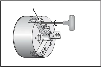
- Use a hex key to loosen the two SHCS attaching the jaw to the chuck.
- Slide jaw to new position and re-tighten the two SHCS.
- Repeat procedure for remaining two jaws. Jaws must remain concentric.
TAPER COMPENSATION
Deflection of the part occurs if it is not supported precisely in the center, or if is too long and unsupported. This causes the cut to be too shallow so the resultant part is under-cut. This can apply to O.D and I.D cutting. Taper Compensation provides the ability to compensate by adding in a calculated value to the X movement based on the position of the Z cut. The zero point of the taper is defined to be the 0.0 of the work-zero coordinate of Z. The taper is entered on the tool shift page as a 5 place number and stored in an array indexed by tool, which is called "Taper" on the Tool Shift/Geometry page. The value entered should be the deflection in the X-axis divided by the length in the Z-axis, over which the deflection occurs. The range of this value is between 0 and .005; this value represents a slope.
LIVE TOOLING
This option is not field installable.
I NTRODUCTION
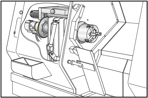
The live tooling option allows the user to drive VDI axial or radial tools to perform such operations as milling, drilling or slotting. The main spindle of the lathe is indexable in one degree increments for precise part positioning and repeatability. Milling shapes is possible using spindle motion G codes.
Programming Notes
- The live tool drive will automatically turn itself off when a tool change is commanded.
- The main spindle can be clamped (M14 and M15) for using the live tooling. It will automatically unclamp when a new main spindle speed is commanded or Reset is pressed.
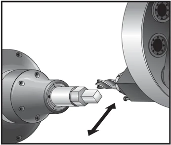
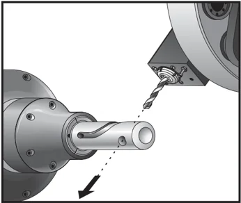
• Maximum live tooling drive speed is 3000 RPM. • Haas live tooling is designed for medium duty milling, e.g.: 3/4" diameter end mill in mild steel max. • Large Tool diameters may require reduction tool holders.
LIVE TOOLING M CODES
Also see the M-Code Chapter.
M19 Angle CMD (Optional) An M19 will orient the spindle to the zero position. A P value can be added that will cause the spindle to orient to a specific position (in degrees.) Degrees of accuracy - P rounds to the nearest whole degree, and R rounds to the nearest hundredth of a degree (x.xx) The angle is viewed in the Current Commands Tool Load screen.
M133 Live Tool Drive Forward M134 Live Tool Drive Reverse M135 Live Tool Drive Stop
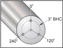
Program Example: Bolt Hole Circle 3 holes @ 120° on 3" BHC G00 X3.0 Z0.1 G98 M19 P0 G04 P2. (Dwell for motor stabilization; length of time depends on set-up) M14 M133 P2000 G01 Z-0.5 F40.0 G00 Z0.1 M19 P120 G04 P2. (Dwell for motor stabilization; length of time depends on set-up) M14 G01 Z-0.5 G00 Z0.1 M19 P240 G04 P2. (Dwell for motor stabilization; length of time depends on set-up) M14 G01 Z-0.5 G00 Z0.1 M15 M13
SYNCHRONOUS MILLING
G32 synchronous motion is a control mode where the X, Z axes are commanded to move distances at constant feed rates and spindle is commanded to rotate at constant speeds.
G32 is commonly used to create threads, the spindle rotates at a constant rpm and constant Z-axis motion begins at the same reference Z-axis mark for each stroke. Many strokes can be repeated because the reference mark sets the location of the start thread.
Geometric shapes can be machined using G32, however, G32 motions can be cumbersome to create and difficult to adjust in the final program. To relieve the user of this burden, the Haas CNC control has a canned cycle G code which simplify the creation of simple geometric shapes. G77, Flatting Cycle, automates the motions of 1 or more sided uniform shapes.
In addition to synchronous motions, G5 is a motion mode that accepts point to point commands and controls the spindle like a rotary device, similar to a rotary table motion. It is commanded in angle and distance point to point motion.
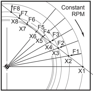
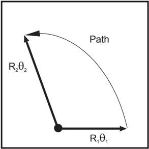
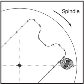
G32 paths between commanded points are curves G32 motion includes both X feed rate and position commands at a constant RPM Using G32, many small motion commands can result in geometric shapes
FINE SPINDLE CONTROL CODES AND LIVE TOOLING G-CODES
Introduction
Many uses of live tooling involve holding the spindle still while performing a cut with the live tool. For certain types of operations, it is necessary to move this spindle in a controlled manner while cutting with the live tool.
Fine Spindle Control (FSC) is most commonly used to create features on or near the face of a part, such as grooves, slots, and flat surfaces. Typically an end mill pointing along the Z-axis is used to perform the cutting, after pilot holes are drilled. Live tooling is almost always required in order to use FSC. Single point turning is not recommended as the surface feet per minute required is too high for the FSC function.
Limitations
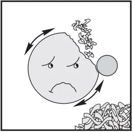
The primary function of the spindle is to turn rapidly. The introduction of G codes for FSC does not change the mechanical design of the spindle motor. Therefore, you should be aware of certain factors that apply when the spindle is turning at very low torque. This limits the depth of cut that can practically be performed with the live tool while the spindle is not locked. In many cases you will want to "track" the motion of the spindle with motion in the X-axis.
 Light Cut
Heavy Cut
Large Cutter
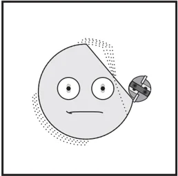
The type of cut and the cutter will have an impact on part finish.
The limit also applies to positioning the spindle in general. This has an effect when trying to perform cuts that are close to centerline.
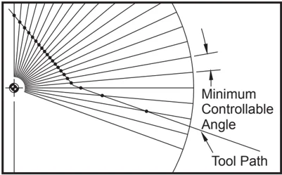
The number of control points depends on radius and direction of cutter path. Cutter paths with a large radius and a shallow angle towards the center will result in few control points.
LIVE TOOLING INSTALLATION
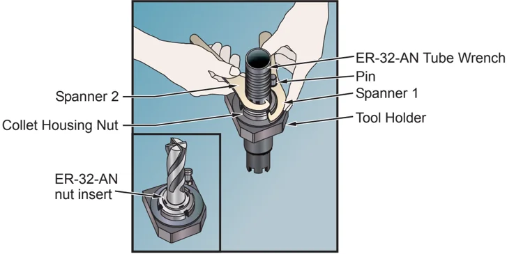
- Insert the tool bit into the ER-AN nut insert. Thread the nut insert into the collet housing nut.
- Place the ER-32-AN tube wrench over the tool bit and engage the teeth of the ER-AN nut insert. Snug the ER-AN nut insert by hand using the tube wrench.
- Place Spanner 1 over the pin and lock it against the collet housing nut. It may be necessary to turn the collet housing nut to engage the spanner.
- Engage the teeth of the tube wrench with Spanner 2 and tighten.
52 Programming 96-8700 rev U June 2008
VDI ADAPTER INSTALLATION
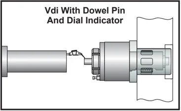
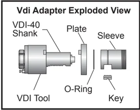
VDI adapters make it possible to use VDI-40 tools in Haas turret.
I nstallation Procedure:
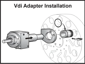
- Install plate over VDI-40 tool shank. Orient plate boss to VDI tool counterbore.
- Slide adapter sleeve onto tool shank with cut-out facing towards base of tool shank. Align cut-out with tooth profile of shank.
- Insert key into sleeve cut-out. Ensure tooth profile of key fits into tool shank properly.
- Place O-ring in the groove as shown. The O-ring will keep the key from falling out.
- Install VDI tool with adapter into turret. Ensure the turret locating pin and plate hole are properly aligned.
- Tighten the draw nut to lock assembly in place.
C-Axis
This option provides high-precision bi-directional spindle motion that is fully interpolated with X and/or Z motion. Spindle speeds from .01 to 60 RPM can be commanded.
C-Axis operation is dependant on the mass, diameter and length of the workpiece and/or the workholding (chuck). Contact the Haas Applications Department if any unusually heavy, large diameter, or long configuration is used.
96-8700 rev U June 2008 Programming 53
OPERATION
M154 C-axis engage
M155 C-axis disengage
Setting 101, Diameter, is used to calculate the feed rate.
The lathe will automatically disengage the spindle brake when the C-axis is commanded to move and to reengage it afterwards (if it has previously been engaged).
C-Axis incremental moves are possible using the “H” address code as shown in the following example.
G0 C90.; (C-axis moves to 90. deg.) H-10.; (C-axis moves to 80. deg.)
SAMPLE PROGRAMS
Example #1
M154 G00 G98 (feed/min) X2.0 Z0 C90 G01 Z-0.1 F6.0 X1.0 C180. F10.0 X2.0 G00 Z0.5 M155
Example #2
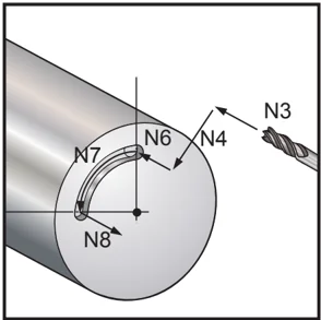
(Assume pilot hole is already drilled.) N1T303 (Small End Mill) N2M19 (Orient Spindle) N3G00 Z0.5 N4G00 X1. N5M133 P1500 N6G98 G1 F10. Z-.25 (Plunge into pre-drilled hole) N7G05 R90. F40.(Make slot) N8G01 F10. Z0.5 (Retract) N9M135 N10 G99 G28 U0 W0
CARTESIAN TO POLAR TRANSFORMATION
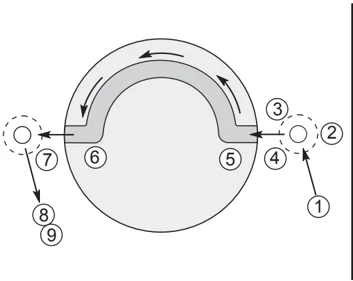
Cartesian to Polar coordinate programming that converts X,Y position commands into rotary C-axis and linear X-axis moves. Cartesian to Polar coordinate programming greatly reduces the amount of code required to command complex moves. Normally a straight line would require many points to define the path, however, in Cartesian, only end points are necessary. This feature allows face machining programming in the Cartesian coordinate system.
Programming notes:
Programmed moves should always position the tool centerline.
Tool paths should never cross the spindle centerline. Cuts that must cross spindle center can be accomplished with two parallel passes on either side of spindle center.
Cartesian to Polar conversion is a modal command (see the G-code section).
54 Programming 96-8700 rev U June 2008
CARTESIAN INTERPOLATION
Cartesian coordinate commands are interpreted into movements of the linear axis (turret movements) and spindle movements (rotation of the work piece).
Example Program
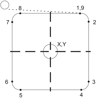
% O00069 N6 (Square) G59 ( TOOL 11, .75 DIA. Endmill ) (Cutting on Center) T1111 M154 G00 C0. G97 M133 P1500 G00 Z1. G00 G98 X2.35 Z0.1 (Position) G01 Z-0.05 F25. G112 G17 G0 X-.75 Y.5 G01 X0.45 F10. (Point 1) G02 X0.5 Y0.45 R0.05 (Point 2) G01 Y-0.45 (Point 3) G02 X0.45 Y-0.5 R0.05 (Point 4) G01 X-0.45 (Point 5) G02 X-0.5 Y-0.45 R0.05 (Point 6) G01 Y0.45 (Point 7) G02 X-0.45 Y0.5 R0.05 (Point 8) G01 X0.45 (Point 9) Y.6 G113 G00 Z3. M30 %
TOOL NOSE CUTTER COMPENSATION USING G112
Tool Nose Cutter Compensation shifts the programmed tool path so that the centerline of the tool is moved to the left or right of the programmed path. The Offset page is used to enter the amount that the tool path is shifted in the radius column. The offset is entered as a radius value for both the geometry values. The compensated value is calculated by the control from the values entered in the Radius. Cutter radius compensation is only available using G17 within G112.
- G41 will select cutter compensation left.
- G42 will select cutter compensation right.
- G40 cancels cutter compensation.
Offset values entered for the radius should be in positive numbers. If the offset contains a negative value, cutter compensation will operate as though the opposite G code was specified. For example, a negative value entered for a G41 will behave as if a positive value was entered for G42.
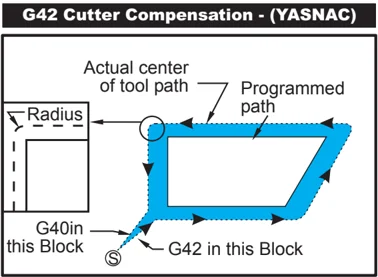
When selecting Yasnac for Setting 58, the control must be able to position the side of the tool along all of the edges of the programmed contour without over cutting the next two motions. A circular motion joins all of the outside angles.
96-8700 rev U June 2008 Programming 55
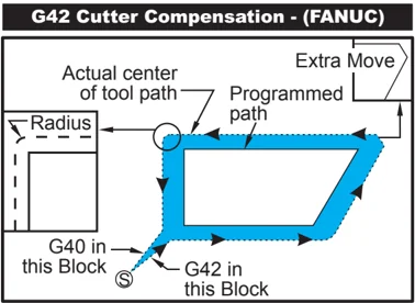
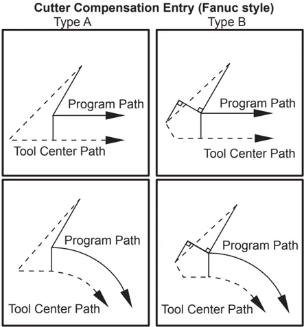
When selecting Fanuc for Setting 58, the control does not require that the tool cutting edge be placed along all edges of the programmed contour, preventing over-cutting. Outside angles less than or equal to 270° are joined by a sharp corner and outside angles of more than 270° are joined by an extra linear motion. The following diagrams show how cutter compensation works for the two values of Setting 58.
NOTE: When canceled, the programmed path returns to being the same as the center of the cutter path. Cancel cutter comp (G40) before ending a program.
Entry and Exit
Cutting should not be performed when entering and exiting cutter compensation or when changing from left side to right side compensation. When cutter compensation is turned on, the starting position of the move is the same as the programmed position, but the ending position will be offset, to either the left or right of the programmed path, by the amount entered in the radius offset column. In the block that turns off cutter compensation, compensation will be turned off as the tool reaches the end of block position. Similarly, when changing from left to right or right to left side compensation, the starting point of the move needed to change cutter compensation direction will be offset to one side of the programmed path and end at a point that is offset to the opposite side of the programmed path. The result of all this is that the tool moves through a path that may not be the same as the intended path or direction. If cutter compensation is turned on or off in a block without any X-Y move, there is no change made to the tool position until the next X or Y move is encountered.
When turning on cutter compensation in a move that is followed by a second move at an angle of less than 90°, there are two ways of computing the first motion, type A or type B (Setting 43). The first, type A, moves the tool directly to the offset start point for the second cut. The diagrams on the following pages illustrate the differences between type A and type B for both Fanuc and Yasnac settings (Setting 58).
Improper Cutter Compensation Application
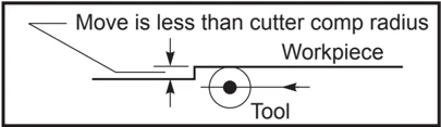
Note that a small cut of less than tool radius and at a right angle to the previous motion will only work with the Fanuc setting. A cutter compensation alarm will be generated if the machine is set to the Yasnac setting.
Feed Adjustments in Cutter Compensation
When using cutter compensation in circular moves, there is the possibility of speed adjustments to what has been programmed. If the intended finish cut is on the inside of a circular motion, the tool should be slowed down to ensure that the surface feed does not exceed what was intended.
Cutter Compensation Entry (YASNAC)
Type A
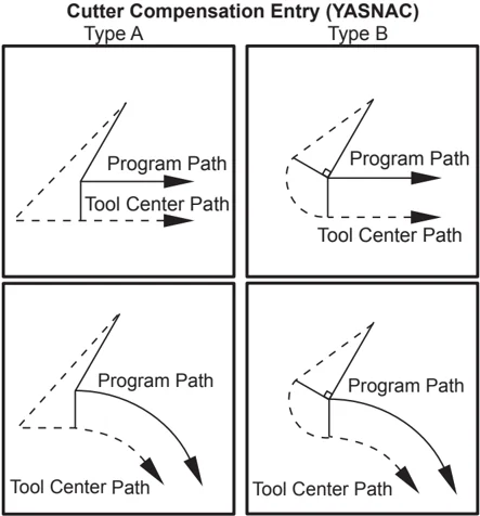
Type B
Cutter Compensation Entry (Fanuc style)
Type A

Type B
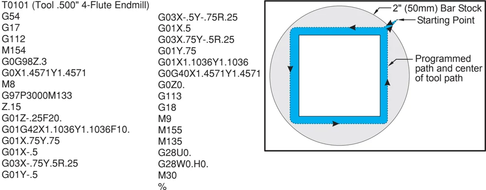
Cutter Compensaiton Example
T0101 (Tool .500" 4-Flute Endmill)
G54 G03X-.5Y-.75R.25 G17 G01X.5 G112 G03X.75Y-.5R.25 M154 G01Y.75 G0G98Z.3 G01X1.1036Y1.1036 G0X1.4571Y1.4571 G0G40X1.4571Y1.4571 M8 G0Z0. G97P3000M133 G113 Z.15 G18 G01Z-.25F20. M9 G01G42X1.1036Y1.1036F10. M155 G01X.75Y.75 M135 G01X-.5 G28U0. G03X-.75Y.5R.25 G28W0.H0. G01Y-.5 M30 %
96-8700 rev U June 2008 Programming 57
TOOL NOSE COMPENSATION
I ntroduction
Tool Nose Compensation is a feature that allows the user to adjust a programmed tool path in response to different cutter sizes or for normal cutter wear. The user can do this by entering minimal offset data at run-time without any additional programming effort.
Programming
Tool Nose Compensation is used when the tool nose radius changes, and cutter wear is to be accounted for with curved surfaces or tapered cuts. Tool Nose Compensation generally does not need to be used when programmed cuts are solely along the X- or Z-axis. For taper and circular cuts, as the tool nose radius changes, under or overcutting can occur. In the figure, suppose that immediately after setup, C1 is the radius of the cutter that cuts the programmed tool path. As the cutter wears to C2, the operator might adjust the tool geometry offset to bring the part length and diameter to dimension. If this were done, a smaller radius would occur. If tool nose compensation is used, a correct cut is achieved. The control will automatically adjust the programmed path based on the offset for tool nose radius as set up in the control. The control will alter or generate code to cut the proper part geometry.
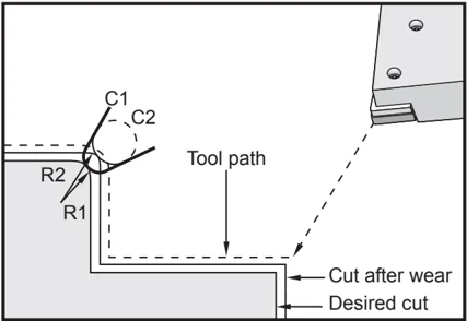
Tool Path for 2 Cutter Radii
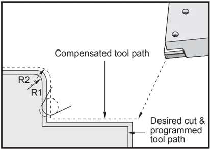
Path Generated when Tool Nose Compensation is used
Note that the second programmed path coincides with the final part dimension. Although parts do not have to be programmed using tool nose compensation, it is the preferred method because it makes program problems easier to detect and resolve.
TOOL NOSE COMPENSATION CONCEPTS
Tool nose compensation works by shifting the Programmed Tool Path to the right or to the left. The programmer will usually program the tool path to the finished size. When tool nose compensation is used, the control will compensate for a the diameter of the tool based on special instructions written into the program. Two G-code commands are used to do this for compensation within a two-dimensional plane. G41 commands the control to shift to the left of the programmed tool path, and G42 commands the control to shift to the right of the programmed tool path. Another command, G40, is provided to cancel any shift made by tool nose compensation.
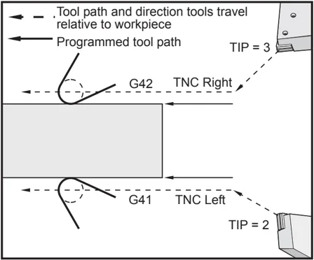
Shift Direction
Imaginary Tool Tip
The shift direction is based on the direction of the tool movement relative to the tool, and which side of the part it is on. When thinking about which direction the compensated shift will occur in tool nose compensation, imagine looking down the tool tip and steering the tool. Commanding G41 will move the tool tip to the left and a G42 will move the tool tip to the right. This means that normal O.D. turning will require a G42 for correct tool compensation, while normal I.D. turning will require a G41.
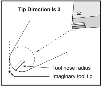
Tool nose compensation assumes that a compensated tool has a radius at the tool tip that it must compensate for. This is called the Tool Nose Radius. Since it is difficult to determine exactly where the center of this radius is, a tool is usually set up using what is called the Imaginary Tool Tip. The control also needs to know which direction the tool tip is relative to the center of the tool nose radius, or the Tip Direction. The tip direction should be specified for each tool.
The first compensated move is generally a move from a non-compensated position to a compensated position and is therefore unusual. This first move is called the "Approach" move and is required when using tool nose compensation. Similarly, a "Depart" move is required. In a depart move, the control moves from a compensated position to a non-compensated position. A depart move occurs when tool nose compensation is cancelled with a G40 command or Txx00 command. Although approach and depart moves can be precisely planned, they are generally uncontrolled moves and the tool should not be in contact with the part when they occur.
USING TOOL NOSE COMPENSATION
The following are the steps used to program a part using TNC:
Program the part to finished dimensions.
Approach and Departure – Ensure that there is an approach move for each compensated path and determine which direction (G41 or G42) is used. Ensure that there is also a departure move for each compensated path.
Tool Nose Radius and Wear – Select a standard insert (tool with radius) to be used for each tool. Set the tool nose radius of each compensated tool. Clear the corresponding tool nose wear offset to zero for each tool.
Tool Tip Direction – Input the tool tip direction for each tool that is using compensation, G41 or G42.
Tool Geometry Offset – Set the tool length geometry and clear the length wear offsets of each tool.
Check Compensation Geometry – Debug the program in graphics mode and correct any tool nose compensation geometry problems that may occur. A problem can be detected in two ways: an alarm will be generated indicating compensation interference, or the incorrect geometry will be seen generated in graphics mode.
Run and Inspect First Article – Adjust compensated wear for the setup part.
APPROACH AND DEPARTURE MOVES FOR TOOL NOSE COMPENSATION
The first X or Z motion in the same line that contains a G41 or G42 is called the "Approach" move. The approach must be a linear move, that is a G01 or G00. The first move is not compensated, yet at the end of the approach move the machine position will be fully compensated. See the following figure.
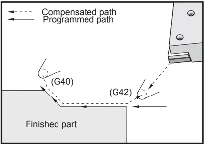
Approach and Departure Moves.
Any line of code with a G40 will cancel tool nose compensation and is called the "Departure" move. The departure must be a linear move, that is a G01 or G00. The start of a departure move is fully compensated; the position at this point will be at a right angle to the last programmed block. At the end of the departure move the machine position is not compensated. See the previous figure.
The following figure shows the condition just prior to cancelling tool nose compensation. Some geometries will result in over or undercutting of the part. This is controlled by including an I and K address code in the G40 cancellation block. The I and K in a G40 block define a vector that is used to determine the compensated target position of the previous block. The vector is usually aligned with an edge or wall of the completed part. The following figure shows how I and J can correct undesired cutting in a departure move.
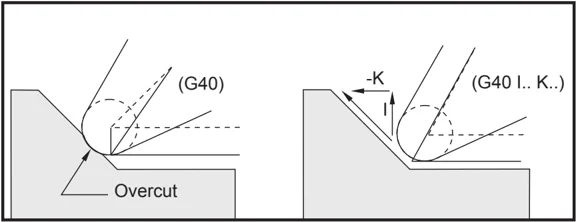
Use of I and K in a G40 block.
TOOL NOSE RADIUS OFFSET AND WEAR OFFSET
Each turning tool that uses tool nose compensation requires a Tool Nose Radius. The tool tip (tool nose radius) specifies how much the control is to compensate for a given tool. If standard inserts are being used for the tool, then the tool nose radius is simply the tool tip radius of the insert.
Associated with each tool on the geometry offsets page is a Tool Nose Radius Offset. The column labeled “Radius” is the value for the tool nose radius of each tool. If the value of any tool nose radius offset is set to zero, no compensation will be generated for that tool.
Associated with each radius offset is a Radius Wear Offset, located on the wear offset page. The control adds the wear offset to the radius offset to obtain an effective radius that will be used for generating compensated values.
Small adjustments (positive values) to the radius offset during production runs should be placed in the wear offset page. This allows the operator to easily track the wear for a given tool. As a tool is used, the insert will generally wear so that there is a larger radius at the end of the tool. When replacing a worn tool with a new one, the wear offset should be cleared to zero.
It is important to remember that tool nose compensation values are in terms of radius rather than diameter. This is important when tool nose compensation is cancelled. If the incremental distance of a compensated departure move is not twice the radius of the cutting tool; overcutting will occur. Always remember that programmed paths are in terms of diameter and allow for twice the tool radius on departure moves. The Q block of canned cycles that require a PQ sequence can often be a departure move. The following example illustrates how incorrect programming will result in overcutting.
Example
Setting 33 is FANUC: X Z Radius Tip Tool Geometry 8: -8.0000 -8.0000 0.0160 2
O0010 ; G28 ; T808 ; (Boring bar) G97 2400 M03 ; G54 G00 X.49 Z.05; G41 G01 X.5156 F.004 ; Z-.05 ; X.3438 Z-.25 Z-.5 ; X.33; (Move less than .032; the value required to avoid cut-in with a departure move before TNC is cancelled.) G40 G00 X.25 ; Z.05 ; G28 ; M30 ;
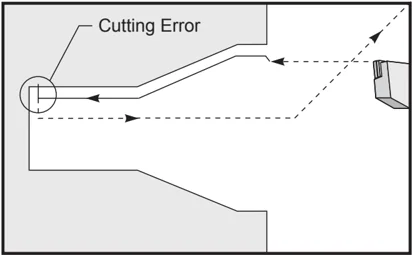
Invalid Program using TNC and G70
96-8700 rev U June 2008 Tool Nose Compensation 61
TOOL NOSE COMPENSATION AND TOOL LENGTH GEOMETRY
The length geometries of tools that use tool nose compensation are set up in the same manner as tools not using compensation. Refer to the “Tooling” section of this manual for details on touching off tools and recording tool length geometries. When a new tool is set up, the geometry wear should be cleared to zero.
Often a tool will exhibit uneven wear. This occurs when particularly heavy cuts occur on one edge of the tool. In this case it may be desirable to adjust the X or Z Geometry Wear rather than the Radius Wear. By adjusting X or Z length geometry wear, the operator can often compensate for uneven tool nose wear. Length geometry wear will shift all dimensions for a single axis.
The program design may not allow the operator to compensate for wear by using length geometry shift. Which wear to adjust can be determined by checking several X and Z dimensions on a finished part. Wear that is even will result in similar dimensional changes on the X and Z axes, and suggests that the radius wear offset should be increased. Wear that affects the dimensions on one axis only suggests length geometry wear.
Good program design based on the geometry of the part being cut should eliminate uneven wear problems. Generally, rely on finishing tools that use the entire radius of the cutter for tool nose compensation.
TOOL NOSE COMPENSATION IN CANNED CYCLES
Some canned cycles ignore tool nose compensation, expect a specific coding structure, or perform their own specific canned cycle activity (also see the “Canned Cycles” section).
The following canned cycles will ignore tool nose radius compensation. Cancel tool nose compensation before any of these canned cycles.
- G74 End face grooving cycle, peck drilling
- G75 O.D./I.D. grooving cycle, peck drilling
- G76 Thread cutting cycle, multiple pass
- G92 Thread cutting cycle, modal
EXAMPLE PROGRAMS USING TOOL NOSE COMPENSATION
Example 1
General Tool Nose Compensation using standard interpolation modes G01/G02/G03.
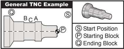
Preparation
Turn Setting 33 to FANUC.
Set up the following tools
- T1 Insert with .0312 radius, roughing
- T2 Insert with .0312 radius, finishing
- T3 .250 wide grooving tool with .016 radius/same tool for offsets 3 and 13
| Tool | Offset | X | Z | Radius | Tip |
|---|---|---|---|---|---|
| T1 | 01 | -8.9650 | -12.8470 | .0312 | 3 |
| T2 | 02 | -8.9010 | -12.8450 | .0312 | 3 |
| T3 | 03 | -8.8400 | -12.8380 | .016 | 3 |
| T3 | 13 | “ | -12.588 | .016 | 4 |
62 Tool Nose Compensation 96-8700 rev U June 2008
Program Example
% O0811 (G42 Test BCA) N1 G54 S1000 T101 G97 S500 M03 G54 G00 X2.1 Z0.1 G96 S200 G71 P10 Q20 U0.02 W0.005 D.1 F0.015 N10 G42 G00 X0. Z0.1 F.01 G01 Z0 F.005 X0.65 X0.75 Z-0.05 Z-0.75 G02 X1.25 Z-1. R0.25 G01 Z-1.5 G02 X1. Z-1.625 R0.125 G01 Z-2.5 G02 X1.25 Z-2.625 R0.125 G01 Z-3.5 X2. Z-3.75 N20 G00 G40 X2.1 G97 S500 G28 M01 N2 G50 S1000 T202 G97 S750 M03 G00 X2.1 Z0.1 G96 S400 G70 P10 Q20 G97 S750 G28 M01 N3 G50 S1000 T303 G97 S500 M03 G54 G42 X1.5 Z-2.0 G96 S200 G01 X1. F0.003 G01 Z-2.5 G02 X1.25 Z-2.625 R0.125 G40 G01 X1.5 T313 G00 G41 X1.5 Z-2.125 G01 X1. F0.003 G01 Z-1.625 G03 X1.25 Z-1.5 R0.125 G40 G01 X1.6 G97 S500 G28 M30 %
Description
(Example1)
(Select tool 1 and offset 1 - tip direction for offset 1 is 3)
(Move to point S)
(Rough P to Q with T1 Using G71 and TNC)
(Define part path PQ sequence)
(P)(G71 Type II, TNC right)
(A)
(B)
(TNC Cancel)
(Zero for tool change clearance)
(Select tool 2 and offset 2 Tip direction is 3)
(move to point S)
(Finish P to Q with T2 using G70 and TNC)
(Zero for tool change clearance)
(Select tool 3, offset 3 Tip direction is 3)
(Groove to point B Using Offset 3)
(Move to point C TNC right
(B)
(TNC cancel - Groove to point A using offset 4)
(Change offset to other side of tool)
(Move to point C - TNC approach)
(A)
(TNC cancel)
Note that the suggested template of the previous section for G70 is used. Also note that compensation is enabled in the PQ sequence but is cancelled after G70 is completed.
Example 2
TNC with a G71 roughing canned cycle
Preparation
Turn Setting 33 to FANUC.
Tools
T1 Insert with .032 radius, roughing
| Tool | Offset | Radius | Tip |
|---|---|---|---|
| T1 | 01 | .032 | 3 |
Program Example
% O0813 G50 S1000 T101 G00 X1.5 Z.1 G96 S100 M03 G71 P80 Q180 U.01 W.005 D.08 F.012
N80 G42 G00 X0.6 G01 Z0 F0.01 X0.8 Z-0.1 Fx0.005 Z-0.5 G02 X1.0 Z-0.6 I0.1 G01 X1.5 X2.0 Z-0.85 Z-1.6 X2.3 G03 X2.8 Z-1.85 K-0.25 G01 Z-2.1 N180 G40 G00 X3.0 M05 G28 M30 %
Description
(Example 3)
(Select tool 1)
(Rapid to start point)
(Rough P to Q with T1 using G71 and TNC)
(Define Part Path PQ sequence)
(P) (G71 Type I, TNC right)
(Start of finish part path)
(Q) (End of part path)
(TNC cancel)
(Zero X for tool change clearance)
Note that this part is a G71 Type I path. When using TNC it is very unusual to have a Type II path. This is because the current compensation methods can only compensate the tool tip in one direction.
64 Tool Nose Compensation 96-8700 rev U June 2008
Example 3
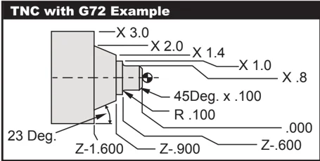
TNC with a G72 roughing canned cycle
Preparation
Setting 33 FANUC
Tools
T1 insert with .032 radius, roughing
T2 insert with .016 radius, finishing
| Tool | Offset | Radius | Tip |
|---|---|---|---|
| T1 | 01 | .032 | 3 |
| T2 | 02 | .016 | 3 |
Program Example
% O0814 G50 S1000 T101 G00 X3.5 Z0.1 G96 S190 M03 (Rough P to Q with T1 using G72 and TNC) G72 P80 Q180 U0.005 W0.01 D0.05 F.010 (Define part path PQ sequence) N80 G41 G00 Z-1.6 G01 X2. F0.005 X1.4 Z-0.9 X1.0 Z-0.6 G03 X0.8 Z-0.5 K0.1 G01 Z-0.1 X0.6 Z0. X0. N180 G40 G00 Z0.01 (Optional Finishing Sequence) G28 M01 T202 N2 G50 S1000 G00 X3.5 Z0.1 G96 S325 M03 G70 P80 Q180 G00 Z0.5 M05 G28 M30 %
Description
(Example 3)
(Select tool 1)
(Move to start point)
(P) (G72 Type I, TNC left)
(TNC Cancel)
(Zero for tool change clearance)
(Select tool 2)
(Move to start point)
(Finish P to Q with T2 using G70 and TNC)
(Zero for tool change clearance)
G72 is used instead of G71 because the roughing strokes in X are longer than the Z roughing strokes of a G71. It is therefore more efficient to use G72.
96-8700 rev U June 2008 Tool Nose Compensation 65
Example 4
TNC with a G73 roughing canned cycle
Preparation
Turn Setting 33 to FANUC
Tools
T1 Insert with .032 radius, roughing
T2 Insert with .016 radius, finishing
| Tool | Offset | Radius | Tip |
|---|---|---|---|
| T1 | 01 | .032 | 3 |
| T2 | 02 | .016 | 3 |
Program Example
% O0815 T101 G50 S1000 G00 X3.5 Z.1 G96 S100 M03 G73 P80 Q180 U.01 W0.005 I0.3 K0.15 D4 F.012 N80 G42 G00 X0.6 G01 Z0 F0.1 X0.8 Z-0.1 F.005 Z-0.5 G02 X1.0 Z-0.6 I0.1 G01 X1.4 X2.0 Z-0.9 Z-1.6 X2.3 G03 X2.8 Z-1.85 K-0.25 G01 Z-2.1 N180 G40 X3.1 G00 Z0.1 M05 (Optional Finishing Sequence) G28 M01 T202 N2 G50 S1000 G00 X3.0 Z0.1 G96 S100 M03 (Finish P to Q with T2 using G70 and TNC) G70 P80 Q180 G00 Z0.5 M05 G28 M30 %
Description
(Example 4)
(Select Tool 1)
(Move to point S)
(Rough P to Q with T1 using G73 and TNC)
(Part path PQ sequence, G72 Type I, TNC right)
(Q)
(TNC Cancel)
(Zero for tool change clearance)
(Select tool 2)
(Move to start point)
(Zero for tool change clearance)
G73 is best used when you want to remove a consistent amount of material in both the X and Z axes.
66 Tool Nose Compensation 96-8700 rev U June 2008
Example 5
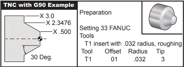
TNC with a G90 modal rough turning cycle
Program Example Description
% O0816 T101 G50 S1000 G00 X4.0 Z0.1 G96 S100 M03 (ROUGH 30 DEG. ANGLE TO X2. AND Z-1.5 USING G90 AND TNC) G90 G42 X2.55 Z-1.5 I-0.9238 F0.012 X2.45 X2.3476 G00 G40 X3.0 Z0.1 M05 G28 M30 %
Example 6
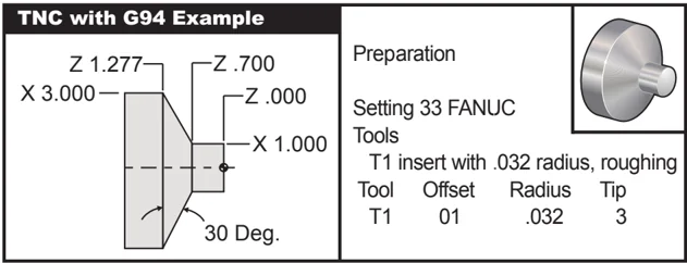
TNC with a G94 modal rough turning cycle
Program Example
% O0817 G50 S1000 T101 G00 X3.0 Z0.1 G96 S100 M03 G94 G41 X1.0 Z-0.5 K-0.577 F.03 Z-0.6 Z-0.7 G00 G40 X3. Z0.1 M05 G28 M30 %
Description
(Example 6)
(Select tool 1)
(Move to start point)
(Rough 30° angle to X1. and Z-0.7 using G94 and TNC)
(Optional additional passes)
(TNC Cancel)
(Zero for tool change clearance)
IMAGINARY TOOL TIP AND DIRECTION
For a lathe it is not easy to determine the center of a tool radius. The cutting edges are set when a tool is touched off to record tool geometry. The control can calculate where the center of the tool radius is by using the edge information, the tool radius, and the direction the cutter is expected to cut in. The X- and Z-axis geometry offsets intersect at a point, called the Imaginary Tool Tip, that aids in determining the tool tip direction. The Tool Tip Direction is determined by a vector originating from the center of the tool radius and extending to the imaginary tool tip. See the following figures.
The tool tip direction of each tool is coded as a single integer from 0 to 9. The tip direction code is found next to the radius offset on the geometry offsets page. It is recommended that a tip direction be specified for all tools using tool nose compensation. The following figure is a summary of the tip coding scheme along with cutter orientation examples.
Note that the tip indicates to the setup person how the programmer intends to measure the tool offset geometry. For example, if the setup sheet shows tip direction 8, the programmer intends the tool geometry to be at the edge of and on the centerline of the tool insert.
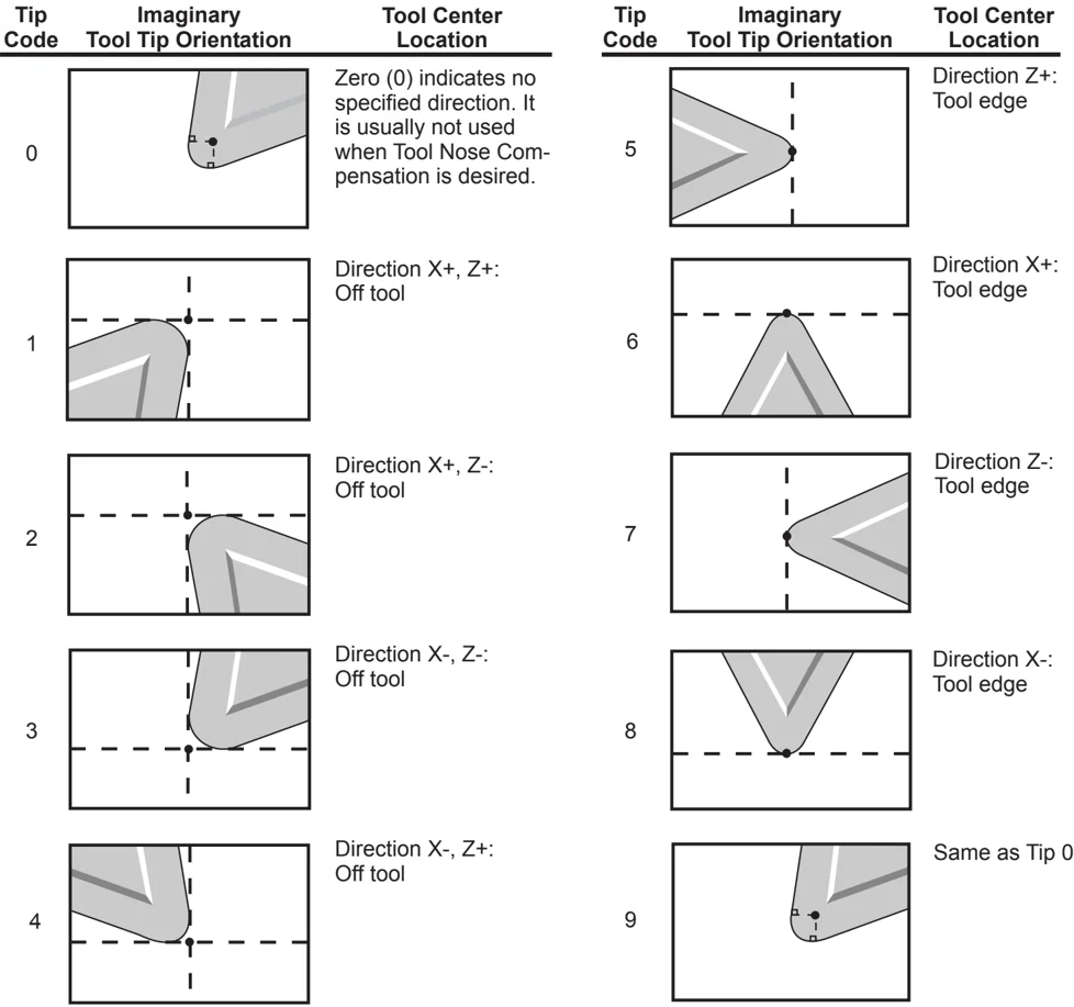
68 Tool Nose Compensation 96-8700 rev U June 2008
PROGRAMMING WITHOUT TOOL NOSE COMPENSATION
Manually Calculating Compensation
When you program a straight line in either X or Z axes the tool tip touches the part at the same point where you touched your original tool offsets in X and Z axes. However, when you program a chamfer or an angle, the tip does not touch the part at those same points. Where the tip actually touches the part is dependent upon the degree of angle being cut and also the size of the tool insert. Programming a part without using any compensation, overcutting and undercutting will occur.
The following pages contain tables and illustrations demonstrating how to calculate the compensation in order to program the part accurately.
Along with each chart are three examples of compensation using both types of inserts and cutting along three different angles. Next to each illustration is a sample program and explanation of how the compensation was calculated.
Refer to the illustrations on the following pages.
The tool tip is shown as a circle with X and Z points called out. These points designate where the X diameter and Z face offsets are touched off.
Each illustration is a 3" diameter part with lines extending from the part and intersecting at 30°, 45° and 60° angles.
The point at which the tool tip intersects the lines is where the compensation value is measured.
The compensation value is the distance from the face of the tool tip to the corner of the part. Notice that the tool tip is slightly offset from the actual corner of the part; this is so the tool tip is in the correct position to make the next move and to avoid any overcutting or undercutting.
Use the values found on the charts (angle and radius size) to calculate the correct tool path position for the program.
TOOL NOSE COMPENSATION GEOMETRY
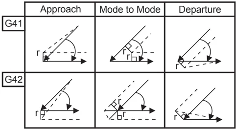
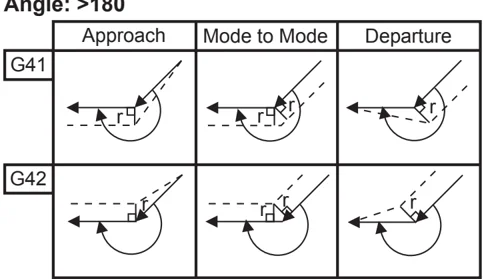
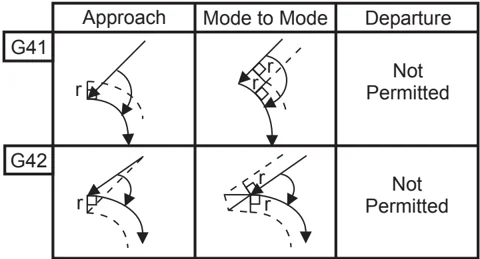
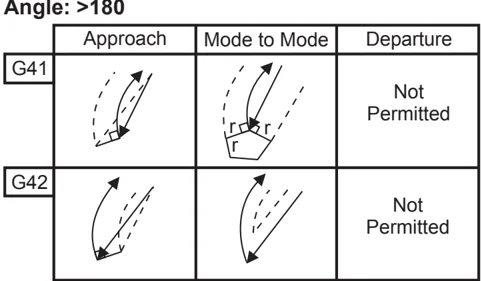
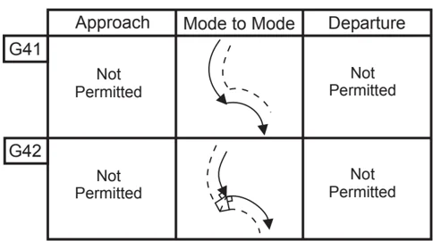
The following figure shows the various geometries of tool nose compensation. It is organized into four categories of intersection. The intersections can be: 1) linear to linear, 2) linear to circular, 3) circular to linear, or 4) circular to circular. Beyond these categories the intersections are classified into angle of intersection and approach, mode to mode, or departure motions.
Two FANUC compensation types are supported, Type A and Type B. The default compensation is Type A.
Linear-to-Linear (Type A)
Angle: <90
| Approach | Mode to Mode | Departure | |
|---|---|---|---|
| G41 | |||
| G42 |
Angle: >=90, <180
| Approach | Mode to Mode | Departure | |
|---|---|---|---|
| G41 | |||
| G42 |
Angle: >180
| Approach | Mode to Mode | Departure | |
|---|---|---|---|
| G41 | |||
| G42 |
Linear-to-Circular (Type A)
Angle: <90
| Approach | Mode to Mode | Departure | |
|---|---|---|---|
| G41 | Not Permitted | ||
| G42 | Not Permitted |
Angle: >=90, <180
| Approach | Mode to Mode | Departure | |
|---|---|---|---|
| G41 | Not Permitted | ||
| G42 | Not Permitted |
Angle: >180
| Approach | Mode to Mode | Departure | |
|---|---|---|---|
| G41 | Not Permitted | ||
| G42 | Not Permitted |
70 Tool Nose Compensation 96-8700 rev U June 2008
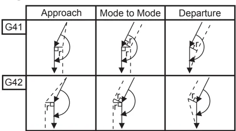
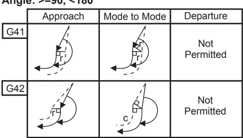
Circular-to-Linear (Type A)
Angle: <90
| Approach | Mode to Mode | Departure | |
|---|---|---|---|
| G41 | Not Permitted | ||
| G42 | Not Permitted |
Angle: >=90, <180
| Approach | Mode to Mode | Departure | |
|---|---|---|---|
| G41 | Not Permitted | ||
| G42 | Not Permitted |
Angle: >180
| Approach | Mode to Mode | Departure | |
|---|---|---|---|
| G41 | Not Permitted | ||
| G42 | Not Permitted |
Circular-to-Circular (Type A)
Angle: <90
| Approach | Mode to Mode | Departure | |
|---|---|---|---|
| G41 | Not Permitted | Not Permitted | |
| G42 | Not Permitted | Not Permitted |
Angle: >=90, <180
| Approach | Mode to Mode | Departure | |
|---|---|---|---|
| G41 | Not Permitted | Not Permitted | |
| G42 | Not Permitted | Not Permitted |
Angle: >180
| Approach | Mode to Mode | Departure | |
|---|---|---|---|
| G41 | Not Permitted | Not Permitted | |
| G42 | Not Permitted | Not Permitted |
96-8700 rev U June 2008 Tool Nose Compensation 71
Tool Nose Radius Calculation Diagram

Program
| Code | Compensation (1/32 TNR) |
|---|---|
| G0 X0 Z.1 | |
| G1 Z0 | |
| X.4736 | (X.5 - 0.0264 Comp) |
| X 3.0 Z-2.188 | (Z-2.1651 + 0.0229 Comp) |
Note: Compensation Value For 30° Angle
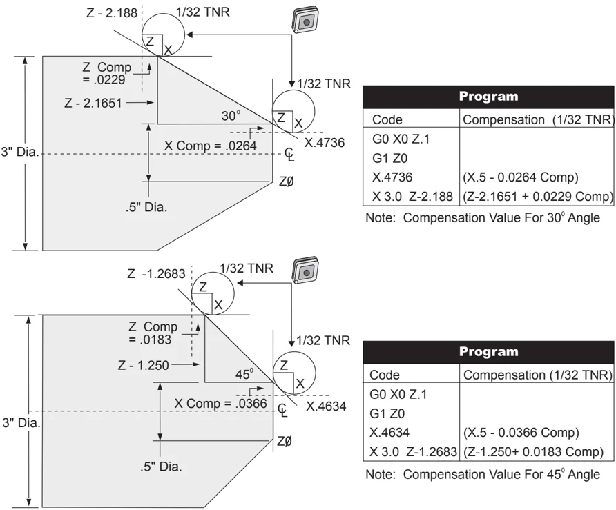
Program
| Code | Compensation (1/32 TNR) |
|---|---|
| G0 X0 Z.1 | |
| G1 Z0 | |
| X.4634 | (X.5 - 0.0366 Comp) |
| X 3.0 Z-1.2683 | (Z-1.250+ 0.0183 Comp) |
Note: Compensation Value For 45° Angle
72 Tool Nose Compensation 96-8700 rev U June 2008
Tool Radius And Angle Chart (1/32 RADIUS)
The X measurement calculated is based on part diameter.
| ANGLE | Xc CROSS | Zc LONGITUDINAL | ANGLE | Xc CROSS | Zc LONGITUDINAL |
|---|---|---|---|---|---|
| 1. | .0010 | .0310 | 46. | .0372 | .0180 |
| 2. | .0022 | .0307 | 47. | .0378 | .0177 |
| 3. | .0032 | .0304 | 48. | .0386 | .0173 |
| 4. | .0042 | .0302 | 49. | .0392 | .0170 |
| 5. | .0052 | .0299 | 50. | .0398 | .0167 |
| 6. | .0062 | .0296 | 51. | .0404 | .0163 |
| 7. | .0072 | .0293 | 52. | .0410 | .0160 |
| 8. | .0082 | .0291 | 53. | .0416 | .0157 |
| 9. | .0092 | .0288 | 54. | .0422 | .0153 |
| 10. | .01 | .0285 | 55. | .0428 | .0150 |
| 11. | .0011 | .0282 | 56. | .0434 | .0146 |
| 12. | .0118 | .0280 | 57. | .0440 | .0143 |
| 13. | .0128 | .0277 | 58. | .0446 | .0139 |
| 14. | .0136 | .0274 | 59. | .0452 | .0136 |
| 15. | .0146 | .0271 | 60. | .0458 | .0132 |
| 16. | .0154 | .0269 | 61. | .0464 | .0128 |
| 17. | .0162 | .0266 | 62. | .047 | .0125 |
| 18. | .017 | .0263 | 63. | .0474 | .0121 |
| 19. | .018 | .0260 | 64. | .0480 | .0117 |
| 20. | .0188 | .0257 | 65. | .0486 | .0113 |
| 21. | .0196 | .0255 | 66. | .0492 | .0110 |
| 22. | .0204 | .0252 | 67. | .0498 | .0106 |
| 23. | .0212 | .0249 | 68. | .0504 | .0102 |
| 24. | .022 | .0246 | 69. | .051 | .0098 |
| 25. | .0226 | .0243 | 70. | .0514 | .0094 |
| 26. | .0234 | .0240 | 71. | .052 | .0090 |
| 27. | .0242 | .0237 | 72. | .0526 | .0085 |
| 28. | .025 | .0235 | 73. | .0532 | .0081 |
| 29. | .0256 | .0232 | 74. | .0538 | .0077 |
| 30. | .0264 | .0229 | 75. | .0542 | .0073 |
| 31. | .0272 | .0226 | 76. | .0548 | .0068 |
| 32. | .0278 | .0223 | 77. | .0554 | .0064 |
| 33. | .0286 | .0220 | 78. | .056 | .0059 |
| 34. | .0252 | .0217 | 79. | .0564 | .0055 |
| 35. | .03 | .0214 | 80. | .057 | .0050 |
| 36. | .0306 | .0211 | 81. | .0576 | .0046 |
| 37. | .0314 | .0208 | 82. | .0582 | .0041 |
| 38. | .032 | .0205 | 83. | .0586 | .0036 |
| 39. | .0326 | .0202 | 84. | .0592 | .0031 |
| 40. | .0334 | .0199 | 85. | .0598 | .0026 |
| 41. | .034 | .0196 | 86. | .0604 | .0021 |
| 42. | .0346 | .0193 | 87. | .0608 | .0016 |
| 43. | .0354 | .0189 | 88. | .0614 | .0011 |
| 44. | .036 | .0186 | 89. | .062 | .0005 |
| 45. | .0366 | .0183 |
96-8700 rev U June 2008 Tool Nose Compensation 73