SYSTEM VARIABLES IN-DEPTH
Variables #750 and #751
These macro variables collect the input from serial port 2. The programmer can test for data queued in the serial port 2 buffer, and collect the data for processing. Macro variable #750 informs the programmer if data is waiting in the RS232 port 2. A value of 1 means that the receive buffer has data queued, otherwise a value of 0 is returned. Macro variable 751 collects the first character from the input buffer, when data is queued; therefore, buffer content is first checked to see if it is empty; if not, the value of the next character queued is returned.
1-Bit Discrete Inputs
Inputs designated as “Spare” can be connected to external devices and used by the programmer.
1-Bit Discrete Outputs
The Haas control is capable of controlling up to 56 discrete outputs. However, a number of these outputs are already reserved for use by the Haas controller.
CAUTION! Do not use outputs that are reserved by the system. Using these outputs may result in injury or damage to your equipment.
The user can change the state of these outputs by writing to variables designated as “spare”. If the outputs are connected to relays, an assignment of “1” sets the relay. An assignment of “0” clears the relay. Referencing these outputs will return the current state of the output and this may be the last assigned value or the last state of the output as set by some user M code. For example, after verifying that output #1108 is “spare”:
#1108 = 1; (Turns #1108 relay on) #101 = #3001+1000; (101 is 1 second from now) WHILE [[#101 GT #3001] AND [#1109 EQ 0]] D01 END1 (Wait here 1 second or until relay #1109 goes high) #1108 = 0; (Turns #1108 relay off)
If the control is not equipped with the M-code relay board, M21 through M28 will be mapped from #1132-#1139. If the M-code relay board is installed, see the 8M-option section for information and instructions.
NOTE: Always test or dry run programs that have been developed for macros that are using new hardware.
Maximum Axis Loads
The following variables are now used to contain the maximum load values for each axis. They can be cleared by cycling power to the machine or by setting the macro to zero in a program (for example, #1064=0;).
1064 = X axis 1264 = C axis 1065 = Y axis 1265 = U axis 1066 = Z axis 1266 = V axis 1067 = A axis 1267 = W axis 1068 = B axis 1268 = T axis
Tool Offsets
Use the following macro variables to read or set the following geometry, shift or wear offset values:
#2001-#2050 X-axis geometry/shift offset #2101-#2150 Z-axis geometry/shift offset #2201-#2250 Tool nose radius geometry #2301-#2350 Tool tip direction #2701-#2750 X-axis tool wear #2801-#2850 Z-axis tool wear #2901-#2950 Tool nose radius wear
96-8700 rev U June 2008 Macros 99
Programmable Messages
#3000 - Alarms can be programmed. A programmable alarm will act just like Haas internal alarms. An alarm is generated by setting the macro variable #3000 to a number between 1 and 999.
#3000 = 15 (Message placed into alarm list) - When this is done, “Alarm” flashes at the bottom of the display and the text in the next comment is placed into the alarm list. The alarm number (in this example, 15) is added to 1000 and used as an alarm number. If an alarm is generated in this manner all motion stops and the program must be reset to continue. Programmable alarms are always numbered between 1000 and 1999. The first 34 characters of the comment will be used for the alarm message.
Timers
Haas macros can access two timers. These timers can be set to a value by assigning a number to the respective variable. A program can then later read the variable and determine the time passed since the timer was set. Timers can be used to imitate dwell cycles, determine part-to-part time or wherever time-dependent behavior is desired.
#3001 Millisecond Timer - The millisecond timer is updated every 20 milliseconds and thus activities can be timed with an accuracy of only 20 milliseconds. At Power On, the millisecond timer is reset. The timer has a limit of 497 days. The whole number returned after accessing #3001 represents the number of milliseconds.
#3002 Hour Timer - The hour timer is similar to the millisecond timer except that the number returned after accessing #3002 is in hours. The hour and millisecond timers can be set independent of each other.
System Overrides
#3003 - Variable 3003 is the Single Block Suppression parameter. It overrides the Single Block function in G-code. In the following example Single Block is ignored when #3003 is set equal to 1. After M3003 is set = 1, each G-code command (lines 2-4) are executed continuously even though the Single Block function is on. When #3003 is set equal to zero, Single Block will operate as normal. That is, the user must press Cycle Start start each line of code (lines 6-8).
#3003=1; G54 G00 G90 X0 Z0; G81 R0.2 Z-0.1 F20 L0; S2000 M03; #3003=0; T02 M06; G83 R0.2 Z-1 F10. L0; X0. Z0.;
Variable #3004
Variable #3004 is a variable that overrides specific control features while running. The first bit disables the Feed Hold button. If feed hold is not to be used during a section of code, put variable #3004, assigned to 1, before the specific lines of code. After that section of code, set #3004 to 0 to restore the function of the Feed Hold button. For example:
Approach code (Feed Hold allowed) #3004=1; (Disables Feed Hold button) Non-stoppable code (Feed Hold not allowed) #3004=0; (Enables Feed Hold button) Depart code (Feed Hold allowed)
100 Macros 96-8700 rev U June 2008
The following is a map of variable #3004 bits and the associated overrides. E = Enabled D = Disabled
| #3004 | FEED HOLD | FEED RATE OVERRIDE | EXACT STOP CHECK |
|---|---|---|---|
| 0 | E | E | E |
| 1 | D | E | E |
| 2 | E | D | E |
| 3 | D | D | E |
| 4 | E | E | D |
| 5 | D | E | D |
| 6 | E | D | D |
| 7 | D | D | D |
#3006 Programmable Stop
Stops can be programmed which act like an M00. The control stops and waits until Cycle Start is pressed. Once Cycle Start is pressed, the program continues with the block after the #3006. In the following example, the first 15 characters of the comment are displayed on the lower left part of the screen.
IF [#1 EQ #0] THEN #3006=101(comment here);
#4001-#4021 Last Block (Modal) Group Codes
The grouping of G codes permits more efficient processing. G codes with similar functions are usually under the same group. For example, G90 and G91 are under group 3. These variables store the last or default G code for any of 21 groups. By reading the group code, a macro program can change the behavior of the G-code. If 4003 contains 91, then a macro program could determine that all moves should be incremental rather than absolute. There is no associated variable for group zero; group zero G codes are Non-modal.
#4101-#4126 Last Block (Modal) Address Data
Address codes A-Z (excluding G) are maintained as modal values. The information represented by the last line of code interpreted by the lookahead process is contained in variables 4101 through 4126. The numeric mapping of variable numbers to alphabetic addresses corresponds to the mapping under alphabetic addresses. For example, the value of the previously interpreted D address is found in #4107 and the last interpreted I value is #4104. When aliasing a macro to an M-code, you may not pass variables to the macro using variables 1-33; instead, use the values from 4101-4126 in the macro.
#5001-#5005 Last Target Position
The final programmed point for the last motion block can be accessed through variables #5001-#5005, X, Y, Z, A, and B, respectively. Values are given in the current work coordinate system and can be used while the machine is in motion.
Axis Position Variables
#5021 X-axis #5024 A-axis #5027 U-axis #5022 Y-axis #5025 B-axis #5028 V-axis (used for the Haas Bar Feeder) #5023 Z-axis #5026 C-axis
#5021-#5025 Current Machine Coordinate Position
The current position in machine coordinates can be obtained through #5021-#5025, X, Y, Z, A, and B, respectively. The values cannot be read while the machine is in motion. The value of #5023 (Z) has tool length compensation applied to it.
96-8700 rev U June 2008 Macros 101
#5041-#5045 Current Work Coordinate Position
The current position in the current work coordinates can be obtained through #5041-5045, X, Y, Z, A, and B, respectively. The values cannot be read while the machine is in motion. The value of #5043 (Z) has tool length compensation applied to it.
#5061-#5069 Current Skip Signal Position
The position where the last skip signal was triggered can be obtained through #5061-#5069, X, Y, Z, A, B, C, U, V, and W respectively. Values are given in the current work coordinate system and can be used while the machine is in motion. The value of #5063 (Z) has tool length compensation applied to it.
#5081-#5086 Tool Length Compensation
The current total tool length compensation that is being applied to the tool is returned. This includes tool geometry referenced by the current modal value set in the T code plus the wear value.
#6996-#6999 Parameter access using macro variables
It is possible for a program to access parameters 1 to 1000 and any of the parameter bits, as follows:
- #6996: Parameter Number
- #6997: Bit Number (optional)
- #6998: Contains value of parameter number in variable 6996
- #6999: Contains bit value (0 or 1) of parameter bit specified in variable 6997.
Note: Variables 6998 and 6999 are read-only.
Usage
To access the value of a parameter, the number of that parameter is copied into variable 6996, after which, the value of that parameter is available using macro variable 6998, as shown:
#6996=601 (Specify parameter 601) #100=#6998 (Copy the value of parameter 601 to variable #100)
To access a specific parameter bit, the number of that parameter is copied into variable 6996 and the bit number is copied to macro variable 6997. The value of that parameter bit is available using macro variable 6999, as shown:
#6996=57 (Specify parameter 57) #6997=0 (Specify bit zero) #100=#6999 (Copy parameter 57 bit 0 to variable #100)
Note: Parameter bits are numbered 0 through 31. 32-bit parameters are formatted, on-screen, with bit 0 at the top-left, and bit 31 at the bottom-right.
Offsets
All tool work offsets can be read and set within a macro expression. This allows the programmer to preset coordinates to approximate locations, or to set coordinates to values based upon the results of skip signal locations and calculations. When any of the offsets are read, the interpretation lookahead queue is stopped until that block is executed.
| #5201-#5206 | G52 X, Z, Y, A, B, C Offset Values |
|---|---|
| #5221-#5226 | G54 “ “ “ “ “ “ |
| #5241-#5246 | G55 “ “ “ “ “ “ |
| #5261-#5266 | G56 “ “ “ “ “ “ |
| #5281-#5286 | G57 “ “ “ “ “ “ |
| #5301-#5306 | G58 “ “ “ “ “ “ |
| #5321-#5326 | G59 “ “ “ “ “ “ |
| #7001-#7006 | G110 X, Z, Y, A, B, C Offset Values |
| #7021-#7026 | “ “ “ “ “ “ |
| #7381-#7386 | G129 X, Z, Y, A, B, C Offset Values |
Variable Usage
All variables are referenced with a number sign (#) followed by a positive number; such as: #1, #101, and #501. Variables are decimal values that are represented as floating point numbers. If a variable has never been used, it can take on a special “undefined” value. This indicates that it has not been used. A variable can be set to undefined with the special variable #0. #0 has the value of undefined or 0.0 depending on the context it is used in. Indirect references to variables can be accomplished by enclosing the variable number in brackets #[]. The expression is evaluated and the result becomes the variable accessed. For example:
#1=3; #[#1]=3.5 + #1;
This sets the variable #3 to the value 6.5.
Variables can be used in place of G-code address where “address” refers to the letters A..Z.
In the block N1 G0 X1.0; the variables can be set to the following values: #7 = 0; #1 = 1.0; and the block replaced by: N1 G#7 X#1;. The values in the variables at runtime are used as the address values.
ADDRESS SUBSTITUTION
The usual method of setting control addresses A-Z is the address followed by a number. For example: G01 X1.5 Z3.7 F.02; sets addresses G, X, Z, and F to 1, 1.5, 3.7, and 0.02 respectively, and thus instructs the control to move linearly, G01, to position X = 1.5 Z = 3.7 at a feed rate of 0.02 inches per revolution. Macro syntax allows the address value to be replaced with any variable or expression.
The previous statement can be replaced by the following code:
#1 = 1; #2 = .5; #3 = 3.7; #4 = 0.02; G#1 X[#1+#2] Z#3 F#4;
The permissible syntax on addresses A..Z (exclude N or O) is as follows:
If the value of the variable does not agree with the range of the address, then the usual control alarm will result. For instance, the following code would result in an invalid G code alarm because there is no G143 code:
#1 = 143; G#1;
When a variable or expression is used in place of an address value, the value is rounded to the least significant digit. If #1 = .123456, then G1 X#1 would move the machine tool to .1235 on the X-axis. If the control is in the metric mode, the tool would be moved to .123 on the X-axis.’
When an undefined variable is used to replace an address value, that address reference is ignored. For example, if #1 is undefined then the block G00 X1.0 Z#1; becomes G00 X1.0, no Z movement takes place.
Macro Statements
Macro statements are lines of code that allow the programmer to manipulate the control with features similar to any standard programming language. Included are functions, operators, conditional and arithmetic expressions, assignment statements, and control statements. Functions and operators are used in expressions to modify variables or values. Operators are essential to expressions, while functions make the programmer’s job easier.
Functions
Functions are built-in routines that the programmer has available to use. All functions have the form <function_name> [argument]. Functions can be passed any expression as arguments. Functions return floating point decimal values. The function provided with the Haas control are as follows:
96-8700 rev U June 2008 Macros 103
| FUNCTION | ARGUMENT | RETURNS | NOTES |
|---|---|---|---|
| SIN[ ] | Degrees | Decimal | Sine |
| COS[ ] | Degrees | Decimal | Cosine |
| TAN[ ] | Degrees | Decimal | Tangent |
| ATAN[ ] | Decimal | Degrees | Arctangent |
| Same as FANUC | |||
| ATAN[ ]/[1] | |||
| SQRT[ ] | Decimal | Decimal | Square root |
| ABS[ ] | Decimal | Decimal | Absolute value |
| ROUND[ ] | Decimal | Decimal | Round off a decimal |
| FIX[ ] | Decimal | Integer | Truncate fraction |
| ACOS[ ] | Decimal | Degrees | Arccosine |
| ASIN[ ] | Decimal | Degrees | Arcsine |
| #[ ] | Integer | Integer | Variable Indirection |
| DPRNT[ ] | ASCII text | External Output |
Notes on Functions
The function “Round” works differently depending on the context that it is used. When used in arithmetic expressions, any number with a fractional part greater than or equal to .5 is rounded up to the next whole integer; otherwise, the fractional part is truncated from the number.
#1= 1.714 ; #2= ROUND[#1] ; (#2 is set to 2.0) #1= 3.1416 ; #2= ROUND[#1] ; (#2 is set to 3.0)
When round is used in an address expression, the argument “Round” is rounded to the addresses significant precision. For metric and angle dimensions, three-place precision is the default. For inch, four-place precision is the default. Integral addresses such as T are rounded normally.
#1= 1.00333 ; G0 X[ #1 + #1 ] ; (X moves to 2.0067) ; G0 X[ ROUND[ #1 ] + ROUND[ #1 ] ] ; (X moves to 2.0066) ; G0 C[ #1 + #1 ] ; (Axis moves to 2.007) ; G0 C[ ROUND[ #1 ] + ROUND[ #1 ] ] ; (Axis moves to 2.006) ;
Fix vs. Round
#1=3.54; #2=ROUND[#1]; #3=FIX[#1]. #2 will be set to 4. #3 will be set to 3.
Operators
Operators can be classified into: Arithmetic operators, Logical operators, and Boolean operators.
Arithmetic operators consist of the usual unary and binary operators. They are:
-
- Unary plus +1.23
-
- Unary minus -[COS[30]]
-
- Binary addition #1=#1+5
-
- Binary subtraction #1=#1-1
-
- Multiplication #1=#2*#3 / - Division #1=#2/4 MOD - Remainder #1=27 MOD 20 (#1 contains 7)
Logical operators are operators that work on binary bit values. Macro variables are floating point numbers. When logical operators are used on macro variables, only the integer portion of the floating point number is used. The logical operators are: OR - logically OR two values together, XOR - exclusively OR two values together, AND - logically AND two values together
#1=1.0; 0000 0001 #2=2.0; 0000 0010 #3=#1 OR #20000 0011 Here the variable #3 will contain 3.0 after the OR operation. #1=5.0; #2=3.0; IF [#1 GT 3.0] AND [#2 LT 10]] GOTO1 Here control will transfer to block 1 because #1 GT 3.0 evaluates to 1.0 and #2 LT 10 evaluates to 1.0, thus 1.0 AND 1.0 is 1.0 (true) and the GOTO occurs.
Note that care must be taken when using logical operators so that the desired result is achieved.
Boolean operators always evaluate to 1.0 (True) or 0.0 (False). There are six Boolean operators. These operators are not restricted to conditional expressions, but they most often are used in conditional expressions. They are:
EQ - Equal to NE - Not Equal to GT - Greater Than LT - Less Than GE - Greater than or Equal to LE - Less Than or Equal to
The following are four examples of how Boolean and Logical operators can be used:
| Example | Explanation |
|---|---|
| IF [#1 EQ 0.0] GOTO100; | Jump to block 100 if value in variable #1 equals 0.0. |
| WHILE [#101 LT 10] DO1; | While variable #101 is less than 10 repeat loop DO1..END1. |
| #1=[1.0 LT 5.0]; | Variable #1 is set to 1.0 (TRUE). |
| IF [#1 AND #2 EQ #3] GOTO1 | If variable #1 logically ANDed with variable #2 is equal to the value in #3 then control jumps to block 1. |
Expressions
Expressions are defined as any sequence of variables and operators surrounded by the square brackets “[“ and “]”. There are two uses for expressions: conditional expressions or arithmetic expressions. Conditional expressions return False (0.0) or True (any non zero) values. Arithmetic expressions use arithmetic operators along with functions to determine a value.
Conditional Expressions
In the Haas control, All expressions set a conditional value. The value is either 0.0 (False) or the value is non-zero (True). The context in which the expression is used determines if the expression is a conditional expression. Conditional expressions are used in the IF and WHILE statements and in the M99 command. Conditional expressions can make use of Boolean operators to help evaluate a True or False condition.
96-8700 rev U June 2008 Macros 105
The M99 conditional construct is unique to the Haas control. Without macros, M99 in the Haas control has the ability to branch unconditionally to any line in the current subroutine by placing a P code on the same line. For example: N50 M99 P10; branches to line N10. It does not return control to the calling subroutine. With macros enabled, M99 can be used with a conditional expression to branch conditionally. To branch when variable #100 is less than 10 we could code the above line as follows: N50 [#100 LT 10] M99 P10;
In this case, the branch occurs only when #100 is less than 10, otherwise processing continues with the next program line in sequence. Above, the conditional M99 can be replaced with: N50 IF [#100 LT 10] GOTO10;
Arithmetic Expressions
An arithmetic expression is any expression using variables, operators, or functions. An arithmetic expression returns a value, and are usually used in assignment statements, but are not restricted to them. Examples of arithmetic expressions:
#101=#145*#30; #1=#1+1; X[#105+COS[#101]]; #[#2000+#13]=0;
Assignment Statements
Assignment statements allow the programmer to modify variables. The format of an assignment statement is: <expression>=<expression>. The expression on the left of the equal sign must always refer to a macro variable, whether directly or indirectly. The following macro initializes a sequence of variables to any value. Here both direct and indirect assignments are used.
O0300 (Initialize an array of variables) ; N1 IF [#2 NE #0] GOTO2 (B=base variable) ; #3000=1 (Base variable not given) ; N2 IF [#19 NE #0] GOTO3 (S=size of array); #3000=2 (Size of array not given) ; N3 WHILE [#19 GT 0] DO1 ; #19=#19-1 (Decrement count) ; #[#2+#19]=#22 . (V=value to set array to) ; END1 ; M99 ;
The preceding macro could be used to initialize three sets of variables as follows:
G65 P300 B101. S20 (INIT 101..120 TO #0) ; G65 P300 B501. S5 V1 (INIT 501..505 TO 1.0) ; G65 P300 B550. S5 V0 (INIT 550..554 TO 0.0) ;
The decimal point in B101., etc. would be required.
Control Statements
Control statements allow the programmer to branch, both conditionally and unconditionally. They also provide the ability to iterate a section of code based on a condition.
Unconditional Branch (GOTOnnn and M99 Pnnn) - In the Haas control, there are two methods of branching unconditionally. An unconditional branch will always branch to a specified block. M99 P15 will branch unconditionally to block number 15. The M99 can be used whether or not macros is installed and is the traditional method for branching unconditionally in the Haas control. GOTO15 does the same as M99 P15. In the Haas control, a GOTO command can be used on the same line as other G-codes. The GOTO is executed after any other commands like M codes.
Computed Branch (GOTO#n and GOTO [expression]) - Computed branching allows the program to transfer control to another line of code in the same subprogram. The block can be computed as the program is running, using the GOTO [expression] form, or may be passed in through a local variable, as in the GOTO#n form.
106 Macros 96-8700 rev U June 2008
The GOTO will round the variable or expression result that is associated with the Computed branch. For instance, if #1 contains 4.49 and GOTO#1 is executed, the control will attempt to transfer to a block containing N4. If #1 contains 4.5, then execution will transfer to a block containing N5. The following code skeleton could be developed to make a program that ads serial numbers to parts:
O9200 (Engrave digit at current location.) ; (D=Decimal digit to engrave); IF [[#7 NE #0] AND [#7 GE O] AND [#7 LE 9]] GOTO99; #3000=1 (Invalid digit) ; N99 #7=FIX[#7] (Truncate any fractional part) ; ; GOTO#7 (Now engrave the digiT); ; N0 (Do digit zero) ... M99 ; N1 (Do digit one) ; M99 ; N2 (Do digit two) ; ... ; (etc.,...)
The previous subroutine will engrave digit five with the following call: G65 P9200 D5;
Computed GOTOs using expression could be used to branch processing based on the results of reading hardware inputs. An example might look like the following:
GOTO[[#1030*2]+#1031] ; NO (1030=0, 1031=0) ; ... M99; N1 (1030=0, 1031=1) ; ... M99; N2 (1030=1, 1031=0) ; ... M99; N3 (1030=1, 1031=1) ; ... M99;
The discrete inputs always return either 0 or 1 when read. The GOTO[expression] will branch to the appropriate G-code based on the state of the two discrete inputs #1030 and #1031.
Conditional Branch (IF and M99 Pnnnn)
Conditional branching allows the program to transfer control to another section of code within the same subroutine. Conditional branching can only be used when macros are enabled. The Haas control allows two similar methods for accomplishing conditional branching.
IF [] GOTO$n$
As discussed, is any expression that uses any of the six Boolean operators EQ, NE, GT, LT, GE, or LE. The brackets surrounding the expression are mandatory. In the Haas control, it is not necessary to include these operators. For example: IF [#1 NE 0.0] GOTO5; could also be: IF [#1] GOTO5;.
In this statement, if the variable #1 contains anything but 0.0, or the undefined value #0, branching to block 5 will occur; otherwise, the next block will be executed.
In the Haas control, a conditional expression can also be used with the M99 Pnnnn format. For example: G0 X0 Z0 [#1EQ#2] M99 P5;. Here, the conditional is for the M99 portion of the statement only. The machine tool is instructed to X0, Y0 whether or not the expression evaluates to True or False. Only the branch, M99, is executed based on the value of the expression. It is recommended that the IF GOTO version is used if portability is desired.
Conditional Execution (IF THEN)
Execution of control statements can also be achieved by using the IF THEN construct. The format is IF [] THEN ;.
NOTE: To preserve compatibility with FANUC syntax "THEN" may not be used with GOTO$n$.
This format is traditionally used for conditional assignment statements such as: IF [#590 GT 100] THEN #590=0.0;
Variable #590 is set to zero when the value of #590 exceeds 100.0. In the Haas control, if a conditional evaluates to False (0.0), then the remainder of the IF block is ignored. This means that control statements can also be conditioned so that we could write something like: IF [#1 NE #0] THEN G1 X#24 Z#26 F#9;. This executes a linear motion only if variable #1 has been assigned a value. Another example is: IF [#1 GE 180] THEN #101=0.0 M99;. This says that if variable #1 (address A) is greater than or equal to 180, set variable #101 to zero and return from the subroutine.
Here is an example of an "IF" statement that branches if a variable has been initialized to contain any value. Otherwise, processing will continue and an alarm will be generated. Remember, when an alarm is generated, program execution is halted.
N1 IF [#9NE#0] GOTO3 (TEST FOR VALUE IN F) ; N2 #3000=11(NO FEED RATE) ; N3 (CONTINUE) ;
I teration/Looping (WHILE DO END)
Essential to all programming languages is the ability to execute a sequence of statements a given number of times or to loop through a sequence of statements until a condition is met. Traditional G coding allows this with the use of the L address. A subroutine can be executed any number of times by using the L address.
M98 P2000 L5;
This is limited since you cannot terminate execution of the subroutine on condition. Macros allow flexibility with the WHILE-DO-END construct. For example:
WHILE [] DO$n$; ; END$n$;
This executes the statements between DOn and ENDn as long as the conditional expression evaluates to True. The brackets in the expression are necessary. If the expression evaluates to False, then the block after ENDn is executed next. WHILE can be abbreviated to WH. The DOn-ENDn portion of the statement is a matched pair. The value of n is 1-3. This means that there can be no more than three nested loops per subroutine. A nest is a loop within a loop
Although nesting of WHILE statements can only be up to three levels, there really is no limit since each subroutine can have up to three levels of nesting. If there is a need to nest to a level greater than 3, the segment containing the three lowest levels of nesting can be made into a subroutine, thereby overcoming the limitation.
If two separate WHILE loops are in a subroutine, they can use the same nesting index. For example:
#3001=0 (WAIT 500 MILLISECONDS); WH [#3001 LT 500] DO1; END1;
#3001=0 (WAIT 300 MILLISECONDS) ; WH [#3001 LT 300] DO1 ; END1 ;
You can use GOTO to jump out of a region encompassed by a DO-END, but you cannot use a GOTO to jump into it. Jumping around inside a DO-END region using a GOTO is allowed.
An infinite loop can be executed by eliminating the WHILE and expression, for example: DO1; END1;
Executes until the Reset key is pressed.
CAUTION! The following code can be confusing: WH [#1] D01; END1;
In the above example, an alarm results indicating no "Then" was found; "Then" refers to the D01. Change D01 (zero) to DO1 (letter O).
G65 Macro Subroutine Call
G65 is the command that calls a subroutine with the ability to pass arguments to it. The format follows: G65 Pnnnn [Lnnnn] [arguments];
Anything italicized in square brackets is optional. The G65 command requires a P address corresponding to a program number currently in the control's memory. When the L address is used the macro call is repeated the specified number of times. In Example 1, subroutine 1000 is called once without conditions passed to the subroutine. G65 calls are similar to, but not the same as, M98 calls. G65 calls can be nested up to 9 times, which means, program 1 can call program 2, program 2 and call program 3 and program 3 can call program 4.
Example 1:G65 P1000; (Call subroutine 1000 as a macro) M30; (Program stop) O1000; (Macro Subroutine) ... M99; (Return from Macro Subroutine)
Aliasing
Aliasing is a means of assigning a G code to a G65 P##### sequence. For example: G65 P9010 X.5 Z.05 F.01 T1; can be written as: G06 X.5 Z.05 F.01 T1;
Here, we have substituted an unused G code, G06, for G65 P9010. In order for the above block to work we must set the parameter associated with subroutine 9010 to 06 (Parameter 91). Note that G00 and G65 can not be aliased. All other codes between 1 and 255 can be used for aliasing.
Program numbers 9010 through 9019 are reserved for G code aliasing. The following table lists which Haas parameters are reserved for macro subroutine aliasing.
G-Code Aliasing
| Haas Parameter | O Code |
|---|---|
| 91 | 9010 |
| 92 | 9011 |
| 93 | 9012 |
| 94 | 9013 |
| 95 | 9014 |
| 96 | 9015 |
| 97 | 9016 |
| 98 | 9017 |
| 99 | 9018 |
| 100 | 9019 |
M-Code Aliasing
| Haas Parameter | M Macro Call |
|---|---|
| 81 | 9000 |
| 82 | 9001 |
| 83 | 9002 |
| 84 | 9003 |
| 85 | 9004 |
| 86 | 9005 |
| 87 | 9006 |
| 88 | 9007 |
| 89 | 9008 |
| 90 | 9009 |
Setting an aliasing parameter to 0 (zero) disables aliasing for the associated subroutine. If an aliasing parameter is set to a G-code and the associated subroutine is not in memory, then an alarm will be given.
Macros allow additional capabilities to communicate with peripheral devices. One can do digitizing of parts, provide runtime inspection reports, or synchronize controls with user provided devices. The commands provided for this are POPEN, DPRNT[ ] and PCLOS.
Communication preparatory commands
POOPEN and PCLOS are not required on the Haas mill. It has been included so that programs from different controls can be sent to the Haas control.
Formatted output
The DPRNT statement allows the programmer to send formatted text to the serial port. Any text and any variable can be printed to the serial port. The form of the DPRNT statement is as follows:
DPRNT [<text> <#nnnn[wf]>... ] ;
DPRNT must be the only command in the block. In the previous example, <text> is any character from A to Z or the letters (+,-,/,*, and the space). When an asterisk is output, it is converted to a space. The <#nnnn[wf]> is a variable followed by a format. The variable number can be any macro variable. The format [wf] is required and consists of two digits within square brackets. Remember that macro variables are real numbers with a whole part and a fractional part. The first digit in the format designates the total places reserved in the output for the whole part. The second digit designates the total places reserved for the fractional part. The total places reserved for output cannot be equal to zero or greater that eight. Thus the following formats are illegal:
[00] [54] [45] [36] /* not legal formats */
A decimal point is printed out between the whole part and the fractional part. The fractional part is rounded to the least significant place. When zero places are reserved for the fractional part, then no decimal point is printed out. Trailing zeros are printed if there is a fractional part. At least one place is reserved for the whole part, even when a zero is used. If the value of the whole part has fewer digits than have been reserved, then leading spaces are output. If the value of the whole part has more digits than has been reserved, then the field is expanded so that these numbers are printed.
A carriage return is sent out after every DPRNT block.
DPRNT[ ] Examples
| Code | Output | |
|---|---|---|
| N1 | #1= 1.5436; | |
| N2 | DPRNT[X#1[44]*Z#1[03]*T#1[40]] ; | X1.5436 Z 1.544 T 1 |
| N3 | DPRNT[MEASUREDINSIDEDIAMETER**] ; | MEASURED INSIDE DIAMETER |
| N4 | DPRNT[] ; | (no text, only a carriage return) |
| N5 | #1=123.456789 ; | |
| N6 | DPRNT[X-#1[25]] ; | X-123.45679 ; |
Execution
DPRNT statements are executed at block interpretation time. This means that the programmer must be careful about where the DPRNT statements appear in the program, particularly if the intent is to print out.
G103 is useful for limiting lookahead. If you wanted to limit lookahead interpretation to one block, you would include the following command at the beginning of your program: (This actually results in a two block lookahead: G103 P1;). To cancel the lookahead limit, change the command to G103 P0. G103 cannot be used when cutter compensation is active.
Editing
Improperly structured or improperly placed macro statements will generate an alarm. Be careful when editing expressions; brackets must be balanced.
The DPRNT[ ] function can be edited much like a comment. It can be deleted, moved as a whole item, or individual items within the bracket can be edited. Variable references and format expressions must be altered as a whole entity. If you wanted to change [24] to [44], place the cursor so that [24] is highlighted, enter [44] and press the write key. Remember, you can use the jog handle to maneuver through long DPRNT[ ] expressions.
Addresses with expressions can be somewhat confusing. In this case, the alphabetic address stands alone. For instance, the following block contains an address expression in X: G1 X [ COS[ 90 ] ] Z3.0; CORRECT
Here, the X and brackets stand alone and are individually editable items. It is possible, through editing, to delete the entire expression and replace it with a number: G1 X 0 Z3.0; WRONG. This block will result in an alarm at runtime. The correct form looks as follows: G1 X0 Z3.0; CORRECT.
Note that there is no space between the X and the Zero (0). Remember when you see an alpha character standing alone, it is an address expression.
FANUC-STYLE MACRO FEATURES NOT INCLUDED IN HAAS CONTROL
This section lists the FANUC macro features that are not available on the Haas control.
M Aliasing Replace G65 Pnnnn with Mnn PROGS 9020-9029.
| Code | Description |
|---|---|
| G66 | Modal call in Every Motion Block |
| G66.1 | Modal call call in every block |
| G67 | Modal cancel |
| M98 | Aliasing, T Code Prog 9000, Var #149, Enable Bit |
| M98 | Aliasing, S Code Prog 9029, Var #147, enable bit |
| M98 | Aliasing, B Code Prog 9028, Var #146, enable bit |
| SKIP/N | N=1..9 |
| #3007 | Mirror Image On flag each axis |
| #4201-#4320 | Current block modal data |
| #5101-#5106 | Current servo deviation |
Names for Variables for Display Purposes ATAN [ ]/[ ] Arctangent, FANUC version BIN [ ] Conversion from BCD to BIN BCD [ ] Conversion from BIN to BCD FUP [ ] Truncate fraction to ceiling LN [ ] Natural Logarithm EXP [ ] Base E exponentiation ADP [ ] Re-scale VAR to whole number BPRNT [ ]
The following can be used as an alternative methods for achieving the same results for a few unimplemented FANUC macro features.
GOTO-nnnn Searching for a block to jump in the negative direction (i.e. backwards through a program) is not necessary if you use unique N address codes. A block search is made starting from the current block being interpreted. When the end of the program is reached, searching continues from the top of the program until the current block is encountered.
EXAMPLE PROGRAM USING MACROS
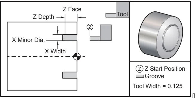
The following example will cut a face groove in a part using easily-edited variables.
% O0010 (MACRO G74) G50 S2000 G97 S1000 M03 T100 G00 T101 #24 = 1.3 (X MINOR DIAMETER) #26 = 0.14 (Z DEPTH) #23 = 0.275 (X GROOVE WIDTH) #20 = 0.125 (TOOL WIDTH) #22 = -0.95 (Z START POSITION) #6 = -1. (ACTUAL Z FACE) #9 = 0.003 (FEED RATE IPR) G00 X [ #24 + [ #23 * 2 ] - [ #20 * 2 ] ] Z#126 G74 U - [ [#23 - #20 ] * 2 ] W - [ #26 + ABS [ #6 - #22 ] ] K [ #20 * 0.75 ] I [ #20 * 0.9 ] F#9 G00 X0 Z0 T100 M30 %
112 Macros 96-8700 rev U June 2008
G CODES - PREPARATORY FUNCTIONS
G codes are used to command specific actions for the machine: such as simple machine moves or drilling functions. They also command more complex features which can involve optional live tooling and the C-axis.
G-codes are divided into groups. Each group of codes is commands for a specific subject. For example, Group 1 G-codes command point-to point moves of the machine axes, Group 7 are specific to the Cutter Compensation feature.
Each group has a dominant G-code; referred to as the default G-code. A default G-code means they are the one in each group the machine uses unless another G-code from the group is specified. For example programming an X, Z move like this, X-2. Z-4. will position the machine using G00. (Note that proper programming technique is to preface all moves with a G-code.)
Default G-codes for each group are shown on the Current Commands screen. If another G code from the group is commanded (active), that G-code is displayed on the Current Commands screen.
G-codes commands can be modal or non-modal. A modal G-code means that once commanded, the G-code will stay in effect until the end of the program or until another G-code from the same group is commanded. A nonmodal G-code is only affects the line it is in; the program line after will not be affected by the previous line's nonmodal G-code. The Group 00 codes are non-modal; the other groups are modal.
Programming Notes
Group 01 G codes will cancel the Group 09 (canned cycles) codes; for example, if a canned cycle (G73 through G89) is active, the use of G00 or G01 will cancel the canned cycle.
Canned Cycles
A canned cycle is used to simplify programming of a part. Canned cycles are defined for most common Z-axis repetitive operations, such as drilling, tapping, and boring. Once selected, a canned cycle is active until canceled with G80. When active, the canned cycle is executed every time an X-axis motion is programmed. X-axis motions are executed as rapid commands (G00) and the canned cycle operation is performed after the X-axis motion.
Using Canned Cycles
Modal canned cycles remain in effect after they are defined and are executed in the Z-axis, for each position of the X-axis. Note that X-axis positioning moves, during a canned cycle will be rapid moves.
The operation of a canned cycle will vary according to whether incremental (U,W) or absolute (X,Z) axis moves are used.
If a loop count (Lnn code number) is defined within the block, the canned cycle will repeat that many times with an incremental (U or W) move between each cycle. Enter the number of repeats (L) each tijme a repeated operation is needed; the number of repeats (L) is not remembered for the next canned cycle.
Spindle control M codes should not be used while a canned cycle is active.
Canned Cycles with Live Tooling
The canned cycles G81, G82, G83, G85, G89 can be used with the live tooling. This parameter prevents the main spindle from turning during one of the above listed canned cycles. If this bit is set to 1, it is the user's responsibility to activate the appropriate spindle prior to performing the canned cycle, that is, some programs must be checked to be sure they explicitly turn on the main spindle before running the canned cycles. Note that G86, G87 and G88 are not usable with live tooling.
G CODE TABLE OF CONTENTS
- G00 Rapid Motion Positioning (Group 01) ........ 116
- G01 Linear Interpolation Motion (Group 01) ........ 116
- G02 CW Circular Interpolation Motion / G03 CCW Circular Interpolation Motion (Group 01) ........ 120
- G04 Dwell (Group 00) ........ 122
- G05 Fine Spindle Control Motion (Group 00) ........ 122
- G09 Exact Stop (Group 00) ........ 123
- G10 Set Offsets (Group 00) ........ 123
- G14 Sub-Spindle Swap / G15 Cancel (Group 17) ........ 123
- G17 XY Plane ........ 123
- G18 ZX Plane Selection (Group 02) ........ 124
- G19 YZ Plane (Group 02) ........ 124
- G20 Select Inches / G21 Select Metric (Group 06) ........ 124
- G28 Return To Machine Zero, set optional G29 Reference point (Group 00) ........ 124
- G29 Return from Reference Point (Group 00) ........ 124
- G31 Skip Function (This G-code is optional and requires a probe) (Group 00) ........ 124
- G32 Thread Cutting (Group 01) ........ 124
- G40 Tool Nose Compensation Cancel (Group 07) ........ 126
- G41 Tool Nose Compensation (TNC) Left / G42 TNC Right (Group 07) ........ 126
- G50 Set Global coordinate Offset FANUC, YASNAC (Group 00) ........ 127
- G50 Spindle Speed Clamp ........ 128
- G51 Cancel Offset (YASNAC) (Group 00) ........ 128
- G52 Set Local Coordinate System FANUC (Group 00) ........ 128
- G53 Machine Coordinate Selection (Group 00) ........ 128
- G54-59 Select Coordinate System #1 - #6 FANUC (Group 12 ) ........ 128
- G61 Exact Stop Modal (Group 15) ........ 128
- G64 Exact Stop Cancel G61 (Group 15) ........ 128
- G70 Finishing Cycle (Group 00) ........ 128
- G71 O.D./I.D. Stock Removal Cycle (Group 00) ........ 129
- G72 End Face Stock Removal Cycle (Group 00) ........ 137
- G73 Irregular Path Stock Removal Cycle (Group 00) ........ 140
- G74 End Face Grooving Cycle, Peck Drilling (Group 00) ........ 141
- G75 O.D./I.D. Grooving Cycle (Group 00) ........ 143
- G76 Threading Cycle, Multiple Pass (Group 00) ........ 145
- G77 Flatting Cycle (This G-code is optional and is used for live tooling) (Group 00) ........ 148
- G80 Canned Cycle Cancel (Group 09*) ........ 150
- G81 Drill Canned Cycle (Group 09) ........ 150
- G82 Spot Drill Canned Cycle (Group 09) ........ 150
- G83 Normal Peck Drilling Canned Cycle (Group 09) ........ 151
- G84 Tapping Canned Cycle (Group 09) ........ 152
- G85 Boring Canned Cycle (Group 09) ........ 152
- G86 Bore and Stop Canned Cycle (Group 09) ........ 153
- G87 Bore and Manual Retract Canned Cycle (Group 09) ........ 153
- G88 Bore and Dwell and Manual Retract Canned Cycle (Group 09) ........ 154
- G89 Bore and Dwell Canned Cycle (Group 09) ........ 154
- G90 O.D./I.D. Turning Cycle (Group 01) ........ 155
- G92 Threading Cycle (Group 01) ........ 155
- G94 End Facing Cycle (Group 01) ........ 157
- G95 Live Tooling Rigid Tap (Face) (Group 09) ........ 158
114 G Codes 96-8700 rev U June 2008
- G96 Constant Surface Speed ON (Group 13) ........ 158
- G97 Constant Surface Speed OFF (Group 13) ........ 158
- G98 Feed Per Minute (Group 10) ........ 158
- G99 Feed Per Revolution (Group 10) ........ 158
- G100 Disable Mirror Image (Group 00) ........ 159
- G101 Enable Mirror Image (Group 00) ........ 159
- G102 Programmable Output to RS-232 (Group 00) ........ 159
- G103 Limit Block Lookahead (Group 00) ........ 159
- G105 Servo Bar Command ........ 159
- G110,G111 and G114-G129 Coordinate System (Group 12) ........ 159
- G112 XY to XC interpretation (Group 04) ........ 159
- G113 G112 Cancel (Group 04) ........ 160
- G112 Program Example ........ 160
- G154 Select Work Coordinates P1-99 (Group 12) ........ 160
- G159 Background Pickup / Part Return ........ 161
- G160 APL Axis Command Mode On ........ 161
- G161 APL Axis Command Mode Off ........ 161
- G184 Reverse Tapping Canned Cycle For Left Hand Threads (Group 09) ........ 161
- G186 Rev Live Tool Rig Tap (Group 09) ........ 162
- G187 Accuracy Control (Group 00) ........ 162
- G195 Live Tool Radial Tapping (Diameter) (Group 00) ........ 162
- G196 Reverse Live Tool Vector Tapping (Diameter) (Group 00) ........ 163
- G200 Index on the Fly (Group 00) ........ 163
G65, the Macro Subroutine Call, is described in the Macro chapter.
G00 Rapid Motion Positioning (Group 01)
*B B-axis motion command *U X-axis incremental motion command *W Z-axis incremental motion command *X X-axis absolute motion command *Z Z-axis absolute motion command
- indicates optional
This G code is used to move the machines axis at the maximum speed. It is primarily used to quickly position the machine to a given point before each feed (cutting) command (All moves are done at full rapid speed). This G code is modal, so a block with G00 causes all following blocks to be rapid motion until another Group 01 code is specified.
Programming note: Generally, rapid motion will not be in a straight line. Each axis specified is moved at the same speed, but all axes will not necessarily complete their motions at the same time. The machine will wait until all motions are complete before starting the next command.
G01 Linear Interpolation Motion (Group 01)
F Feed rate *B B-axis motion command *U X-axis incremental motion command *W Z-axis incremental motion command *X X-axis absolute motion command *Z Z-axis absolute motion command A Optional angle of movement (used with only one of X, Z, U, W) ,C Distance from center of intersection where the chamfer begins ,R Radius of the circle
This G code provides for straight line (linear) motion from point to point. Motion can occur in 1 or 2 axes. All axes will start and finish motion at the same time. The speed of all axes is controlled so that the feed rate specified is achieved along the actual path. The C-axis may also be commanded and this will provide a helical (spiral) motion. C-axis feed rate is dependent on the C-axis diameter setting (Setting 102) to create a helical motion. The F address (feedrate) command is modal and may be specified in a previous block. Only the axes specified are moved. The auxiliary axes B, U, V, and W can also be moved with a G01 but only one axis is moved at a time (except when U,V and W are used with the Advanced Parts Loader ,APL).
Corner Rounding and Chamfering
A chamfer block or a corner rounding block can be automatically inserted between two linear interpolation blocks by specifying ,C (chamfering) or ,R (corner rounding). There must be a terminating linear interpolation block following the beginning block (a G04 pause may intervene). These two linear interpolation blocks specify a theoretical corner of intersection. If the beginning block specifies a ,C the value following the C is the distance from the corner of intersection where the chamfer begins and also the distance from that same corner where the chamfer ends. If the beginning block specifies an ,R the value following the R is the radius of a circle tangent to the corner at two points: the beginning of the corner rounding arc block that is inserted and the endpoint of that arc. There can be consecutive blocks with chamfer or corner rounding specified. There must be movement on the two axes specified by the selected plane (whichever plane that is active X-Y (G17) X-Z (G18) or Y-Z (G19). For chamfering a 90° angle only, a K value can be substituted where ,C is used.
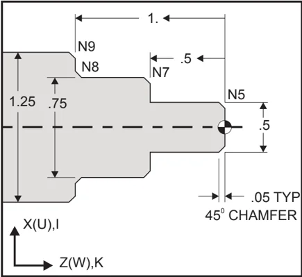
Automatic Chamfering % O0001 (Automatic Chamfering) N1 G50 S1500 N2 G00 T101 G97 S500 M03 N3 G00 X0 Z0.25 N4 G01 Z0 F0.005 N5 G01 X0.50 K-0.050 N6 G01 Z-0.50 N7 G01 X0.75 K-0.050 N8 G01 Z-1.0 I0.050 N9 G01 X1.25 K-0.050 N10 G01 Z-1.5 N11 G00 X1.5 Z0.25 M30 %
The following G-code syntax automatically includes a 45° chamfer or corner radius between two blocks of linear interpolation which intersect a right (90 degree) angle.
Chamfering Syntax Corner Rounding Syntax G01 X(U) x Kk G01 X(U) x Rr G01 Z(W) z li G01 Z(W) z Rr
Addresses I = chamfering, Z to X (X axis direction, +/-, “Radius” value) K = chamfering, X to Z (Z axis direction, +/-) R = corner rounding (X or Z axis direction, +/-, “Radius” value)
NOTE: A -30 = A150; A -45 = A135
G01 Chamfering with A
When specifying an angle (A), command motion in only one of the other axes (X or Z), the other axis is calculated based on the angle.
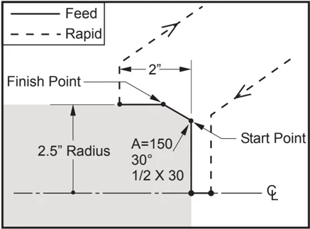
T606 G54; M03 S1500 G97; G00 X5. Z0.1; X0; G01 Z0 F0.01; G01 X4. Z0 F0.012; (Start point) X5. (finish point) A150. (Angle to finish point); Z-2.; X6.; G28; M30;
96-8700 rev U June 2008 G Codes 117
Corner Chamfering
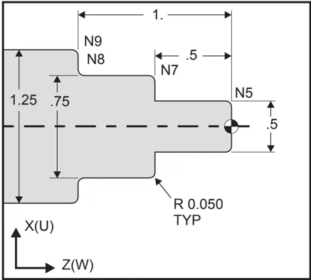
% O0005 (Automatic Corner Rounding) T101; N1 G50 S1500; N2 G00 G97 S500 M03; N3 X0 Z0.25; N4 G01 Z0 F0.005; N5 G01 X0.5 R-0.050; N6 G01 Z-0.50; N7 G01 X0.75 R-0.050; N8 G01 Z-1.0 R0.050; N9 G01 X1.25 R-0.050; N10 G01 Z-1.5; N11 G00 X1.5 Z0.25; G28; M30; %
NOTES: 1) Incremental programming is possible if Ub or Wb is specified in place of Xb or Zb, respectively. So its actions will be as follows: X(POScurrent + i) = Ui, Z(POScurrent +k) = Wk, X(POScurrent +r)=Ur, Z(POScurrent+r)=Wr. 2) POScurrent indicates current position of X or Z axis. 3) I, K and R always specify a radius value (radius programming value)
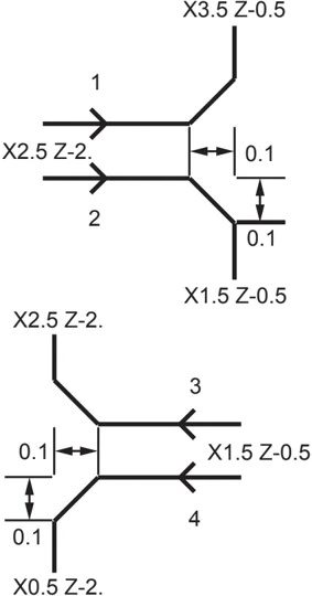
| Chamfering | Code/Example | Movement |
|---|---|---|
| 1. Z+ to X+ | X2.5 Z-2;G01 Z-0.5 I0.1;X3.5; | X2.5 Z-2;G01 Z-0.6;X2.7 Z-0.5;X3.5; |
| 2. Z+ to X- | X2.5 Z-2.;G01 Z-0.5 I-0.1;X1.5; | X2.5 Z-2.;G01 Z-0.6;X2.3 Z-0.5;X1.5; |
| 3. Z- to X+ | X1.5 Z-0.5.;G01 Z-2. I0.1;X2.5; | X1.5 Z-0.5G01 Z-1.9;X1.7 Z-2.;X2.5; |
| 4. Z- to X- | X1.5 Z-0.5.;G01 Z-2. I-0.1;X0.5; | X1.5 Z-0.5;G01 Z-1.9;X1.3 Z-2.X0.5; |
118 G Codes 96-8700 rev U June 2008
Chamfering
| Chamfering | Code Example | Movement |
|---|---|---|
| 1. X- to Z- | X1.5 Z-1.;G01 X0.5 K-0.1;Z-2.; | X1.5 Z-1.;G01 X0.7;X0.5 Z-1.1;Z-2. |
| 2. X- to Z+ | X1.5 Z-1.;G01 X0.5 K0.1;Z0.; | X1.5 Z-1.;G01 X0.7;X0.5 Z-0.9;Z0.; |
| 3. X+ to Z- | X0.5 Z-1.;G01 X1.5 K-0.1;Z-2.; | X0.5 Z-1.;G01 X1.3;X1.5 Z-1.1;Z-2. |
| 4. X+ to Z+ | X0.5 Z-1.;G01 X1.5 K0.1;Z0.; | X0.5 Z-1.;G01 X1.3;X1.5 Z-0.9;Z0.; |

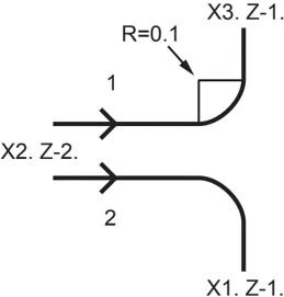
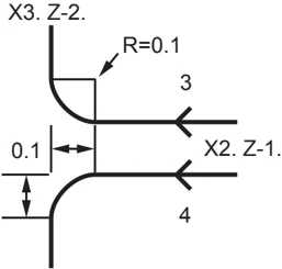
Corner Rounding
| Corner Rounding | Code Example | Movement |
|---|---|---|
| 1. Z+ to X+ | X2. Z-2.;G01 Z-1 R.1;X3.; | X2. Z-2.;G01 Z-1.1;G03 X2.2 Z-1. R0.1;G01 X3.; |
| 2. Z+ to X- | X2. Z-2.;G01 Z-1. R-0.1;X1.; | X2. Z-2.;G01 Z-1.1;G02 X1.8 Z-1 R0.1;G01 X1.; |
| 3. Z- to X+ | X2. Z-1.;G01 Z-2. R0.1;X3.; | X2. Z-1.;G01 Z-1.9;G02 X2.2 Z-2. R0.1;G01 X3.; |
| 4. Z- to X- | X2. Z-1.;G01 Z-2. R-0.1;X1.; | X2. Z-1.;G01 Z-1.9. ;G03 X1.8 Z-2.;G01 X1.; |
96-8700 rev U June 2008 G Codes 119
Corner Rounding
| Corner Rounding | Code Example | Movement |
|---|---|---|
| 1. X- to Z- | X1.5 Z-1.;G01 X0.5 K-0.1;Z-2.; | X1.5 Z-1.;G01 X0.7;X0.5 Z-1.1;Z-2. |
| 2. X- to Z+ | X1.5 Z-1.;G01 X0.5 K0.1;Z0.; | X1.5 Z-1.;G01 X0.7;X0.5 Z-0.9;Z0.; |
| 3. X+ to Z- | X0.5 Z-1.;G01 X1.5 K-0.1;Z-2.; | X0.5 Z-1.;G01 X1.3;X1.5 Z-1.1;Z-2. |
| 4. X+ to Z+ | X0.5 Z-1.;G01 X1.5 K0.1;Z0.; | X0.5 Z-1.;G01 X1.3;X1.5 Z-0.9;Z0.; |
Rules:
-
Use K address only with X(U) address. Use I address only with Z(W) address.
-
Use R address with either X(U) or Z(W), but not both in the same block.
-
Do not use I and K together on the same block. When using R address, do not use I or K.
-
The next block must be another single linear move that is perpendicular to the previous one.
-
Automatic chamfering or corner rounding cannot be used in a threading cycle or in a canned cycle.
-
Chamfer or corner radius must be small enough to fit between the intersecting lines.
-
There should be only a single move along the X or Z in linear mode (G01) for chamfering or corner rounding.
G02 CW Circular Interpolation Motion / G03 CCW Circular Interpolation Motion (Group 01)
| F | Feed rate |
|---|---|
| *I | Distance along X-axis to center of circle |
| *K | Distance along Z-axis to center of circle |
| *R | Radius of arc |
| *U | X-axis incremental motion command |
| *W | Z-axis incremental motion command |
| *X | X-axis absolute motion command |
| *Z | Z-axis absolute motion command |
| ,C | Distance from center of intersection where the chamfer begins |
| ,R | Radius of the circle |
- indicates optional
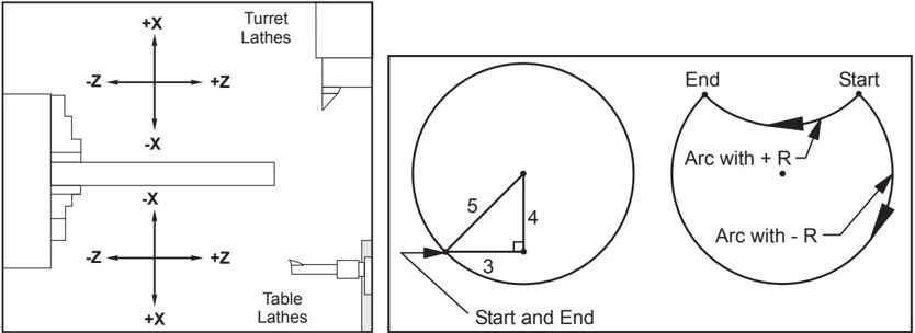
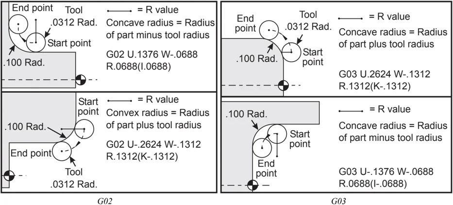
These G codes are used to specify a circular motion (CW or CCW) of the linear axes (Circular motion is possible in the X and Z axes as selected by G18). The X and Z values are used to specify the end point of the motion and can use either absolute (U and W) or incremental motion (X and Z). If either the X or Z is not specified, the endpoint of the arc is the same as the starting point for that axis. There are two ways to specify the center of the circular motion; the first uses I or K to specify the distance from the starting point to the center of the arc; the second uses R to specify the radius of the arc (maximum 7740 inches).
Axis Definitions
G02
G02
G03
R is used to specify the center of the circle. R is the distance from the starting point to the center of the circle. With a positive R, the control will generate a path of 180 degrees or less; to generate a radius of over 180 degrees, specify a negative R. X or Z is required to specify an endpoint if different from the starting point.
The following line will cut an arc of less than 180 degrees:
G01 X3.0 Z4.0
G02 Z-3.0 R5.0
I and K are used to specify the center of the arc. When I and K are used, R may not be used. The I or K is the signed distance from the starting point to the center of the circle. If only one of I or K is specified, the other is assumed to be zero.
96-8700 rev U June 2008
G Codes
121
G04 Dwell (Group 00)
P The dwell time in seconds or milliseconds
G04 is used to cause a delay or dwell in the program. The block containing G04 will delay for the time specified by the P code. For example G04 P10.0. This will delay the program for 10 seconds. Note the use of the decimal point G04 P10. is a dwell of 10 seconds; G04 P10 is a dwell of 10 milliseconds.
G05 Fine Spindle Control Motion (Group 00) (Also see the C-axis section)
R Angular motion of the spindle, in degrees.
F Feed Rate of the center of the tool, in inches per minute.
*U X-axis incremental motion command.
*W Z-axis incremental motion command.
*X X-axis absolute motion command.
*Z Z-axis absolute motion command.
- indicates optional
This G code is used to specify a precise motion of the spindle.
The spindle speed is determined by looking at the greatest X-axis value encountered during the cut.
The largest feed per revolution value that can be specified is approximately 14.77. This means that G5 motions with small R motions relative to X or Z motions will not work. For example, an R motion of 1.5 degrees, the largest X or Z motion that can be specified is 14.77 * 1.5 / 360 = .0615 inches. Conversely, an X or Z motion of .5 inches must have an R travel of at least .5 * 360 / 14.77 = 12.195 degrees.
Simple Face Slot Example with G05
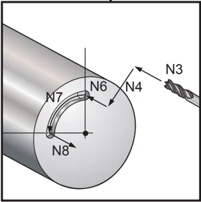
(Assume pilot hole is already drilled.)
N1T303 (Small End Mill)
N2M19 (Orient Spindle)
N3G00 Z0.5
N4G00 X1.
N5M133 P1500
N6G98 G1 F10. Z-.25 (Plunge into pre-drilled hole)
N7G05 R90. F40.(Make slot)
N8G01 F10. Z0.5 (Retract)
N9M135
N10 G99 G28 U0 W0
Simple Cam Example with G05
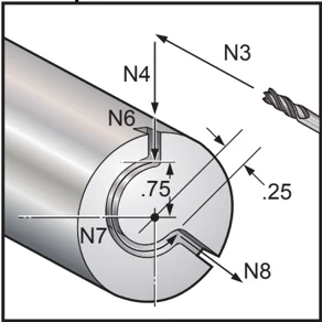
N1 T303 (Small End Mill)
N2M19
N3G00 Z-.25
N4G00 X2.5 (Approach 2" diam stock)
N5M133 P1500
N6G98 G01 X1.5 F40. (Cut to top of cam)
N7G05 R215. X.5 F40. (Cut Cam)
N8G01 X2.5 F40. (Cut out of cam)
N9M135
N10G99 G28 U0 W0
122 G Codes 96-8700 rev U June 2008