Tool Nose Radius Calculation Diagram
30° Case
- Z Comp = .0114
- Z-2.1651
- X Comp = .0132
- 3" Dia.
- .5" Dia.
- Zø
- 1/64 TNR
- X.4868
Program
| Code | Compensation (1/64 TNR) |
|---|---|
| G0 X0 Z.1 | |
| G1 Z0 | |
| X.4868 | (X.5 - 0.0132 Comp) |
| X 3.0 Z-2.1765 | (Z-2.1651 + 0.0114 Comp) |
Note: Using Compensation Values For 30°
45° Case
- Z Comp = .0092
- Z-1.25
- X Comp = .0184
- 3" Dia.
- .5" Dia.
- Zø
- 1/64 TNR
- X.4817
Program
| Code | Compensation(1/64 TNR) |
|---|---|
| G0 X0 Z.1 | |
| G1 Z0 | |
| X.4816 | (X.5 - 0.0184 Comp) |
| X 3.0 Z-1.2592 | (Z-1.25 + 0.0092 Comp) |
Note: Using Compensation Values For 45°
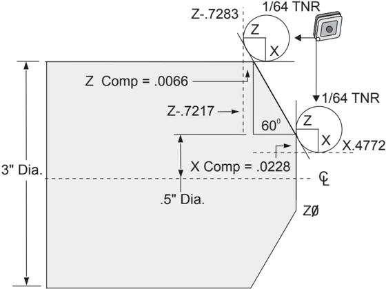
60° Case
- Z Comp = .0066
- Z-.7217
- X Comp = .0228
- 3" Dia.
- .5" Dia.
- Zø
- 1/64 TNR
- X.4772
Program
| Code | Compensation (1/64 TNR) |
|---|---|
| G0 X0 Z.1 | |
| G1 Z0 | |
| X.4772 | (X.5 - 0.0228 Comp) |
| X 3.0 Z-.467 | (Z-.7217 + 0.0066 Comp) |
Note: Using Compensation Values For 60°
Tool Nose Compensation
74 96-8700 rev U June 2008
Tool Radius And Angle Chart (1/64 Radius)
The X measurement calculated is based on part diameter.
| ANGLE | Xc CROSS | Zc LONGITUDINAL | ANGLE | Xc CROSS | Zc LONGITUDINAL |
|---|---|---|---|---|---|
| 1. | .0006 | .0155 | 46. | .00186 | .0090 |
| 2. | .0001 | .0154 | 47. | .0019 | .0088 |
| 3. | .0016 | .0152 | 48. | .0192 | .0087 |
| 4. | .0022 | .0151 | 49. | .0196 | .0085 |
| 5. | .0026 | .0149 | 50. | .0198 | .0083 |
| 6. | .0032 | .0148 | 51. | .0202 | .0082 |
| 7. | .0036 | .0147 | 52. | .0204 | .0080 |
| 8. | .0040 | .0145 | 53. | .0208 | .0078 |
| 9. | .0046 | .0144 | 54. | .021 | .0077 |
| 10. | .0050 | .0143 | 55. | .0214 | .0075 |
| 11. | .0054 | .0141 | 56. | .0216 | .0073 |
| 12. | .0060 | .0140 | 57. | .022 | .0071 |
| 13. | .0064 | .0138 | 58. | .0222 | .0070 |
| 14. | .0068 | .0137 | 59. | .0226 | .0068 |
| 15. | .0072 | .0136 | 60. | .0228 | .0066 |
| 16. | .0078 | .0134 | 61. | .0232 | .0064 |
| 17. | .0082 | .0133 | 62. | .0234 | .0062 |
| 18. | .0086 | .0132 | 63. | .0238 | .0060 |
| 19. | .0090 | .0130 | 64. | .024 | .0059 |
| 20. | .0094 | .0129 | 65. | .0244 | .0057 |
| 21. | .0098 | .0127 | 66. | .0246 | .0055 |
| 22. | .0102 | .0126 | 67. | .0248 | .0053 |
| 23. | .0106 | .0124 | 68. | .0252 | .0051 |
| 24. | .011 | .0123 | 69. | .0254 | .0049 |
| 25. | .0014 | .0122 | 70. | .0258 | .0047 |
| 26. | .0118 | .0120 | 71. | .0260 | .0045 |
| 27. | .012 | .0119 | 72. | .0264 | .0043 |
| 28. | .0124 | .0117 | 73. | .0266 | .0041 |
| 29. | .0128 | .0116 | 74. | .0268 | .0039 |
| 30. | .0132 | .0114 | 75. | .0272 | .0036 |
| 31. | .0136 | .0113 | 76. | .0274 | .0034 |
| 32. | .014 | .0111 | 77. | .0276 | .0032 |
| 33. | .0142 | .0110 | 78. | .0280 | .0030 |
| 34. | .0146 | .0108 | 79. | .0282 | .0027 |
| 35. | .015 | .0107 | 80. | .0286 | .0025 |
| 36. | .0154 | .0103 | 81. | .0288 | .0023 |
| 37. | .0156 | .0104 | 82. | .029 | .0020 |
| 38. | .016 | .0102 | 83. | .0294 | .0018 |
| 39. | .0164 | .0101 | 84. | .0296 | .0016 |
| 40. | .0166 | .0099 | 85. | .0298 | .0013 |
| 41. | .017 | .0098 | 86. | .0302 | .0011 |
| 42. | .0174 | .0096 | 87. | .0304 | .0008 |
| 43. | .0176 | .0095 | 88. | .0308 | .0005 |
| 44. | .018 | .0093 | 89. | .031 | .0003 |
| 45. | .0184 | .0092 |
96-8700 rev U June 2008 Tool Nose Compensation 75
PROGRAMMING
CNC controls use a variety of coordinate systems and offsets that allow control of the location of the tooling point to the part. This section describes interaction between various coordinate systems and tooling offsets.
Effective Coordinate System
The effective coordinate system is the sum total of all coordinate systems and offsets in effect. It is the system that is displayed under the label "Work" on the positions display. It is also the same as the programmed values in a G code program assuming no Tool Nose Compensation is being performed. Effective Coordinate = global coordinate + common coordinate + work coordinate + child coordinate + tool offsets.
FANUC Work Coordinate Systems - Work coordinates are an additional optional coordinate shift relative to the global coordinate system. There are 26 work coordinate systems available on a Haas control, designated G54 through G59 and G110 through G129. G54 is the work coordinate in effect when the control is powered on. The last used work coordinate stays in effect until another work coordinate is used or the machine is powered off. G54 can be deselected by ensuring that the X and Z values on the work offset page for G54 are set to zero.
FANUC Child Coordinate System - A child coordinate is a coordinate system within a work coordinate. Only one child coordinate system is available and it is set through the G52 command. Any G52 set during the program is removed once the program finishes at an M30, Reset or power down.
FANUC Common Coordinate System - The common (Comm) coordinate system is found on the second work coordinate offsets display page just below the global coordinate system (G50). The common coordinate system is retained in memory when power is turned off. The common coordinate system can be changed manually with G10 command or by using macro variables.
YASNAC Work Coordinate Shift - YASNAC controls discuss a work coordinate shift. It serves the same function as the common coordinate system. When Setting 33 is set to YASNAC, it is found on the work offsets display page as T00.
YASNAC Machine Coordinate System - The effective coordinates take the value from machine zero coordinates. Machine coordinates can be referenced by specifying G53 with X and Z in a motion block.
YASNAC Tool Offsets - There are two offsets available: geometry offsets and wear offsets. Geometry offsets adjusts for different lengths and widths of tools, so that every tool comes to the same reference plane. Geometry offsets are usually done at setup time and remain fixed. Wear offsets allow the operator to make minor adjustments to the geometry offsets to compensate for normal tool wear. Wear offsets are usually zero at the beginning of a production run and may change as time progresses. In a FANUC compatible system, both geometry and wear offsets are used in the calculation of the effective coordinate system.
Geometry offsets are not available; they are replaced with tool shift offsets (50 tool shift offsets numbered 51 - 100). YASNAC tool shift offsets modify the global coordinate to allow for varying tool lengths. Tool shift offsets must be used prior to calling for the use of a tool with a G50 Txx00 command. The tool shift offset replaces any previously calculated global shift offset and a G50 command overrides a previously selected tool shift.
 Tool Offset 51
Z
Machine
(0,0)
Tool Offset 51 X/2
Spindle Ⓒ
G50 Work Offset
(0,0)
000101 N1 G51 (Return to Machine Zero) N2 G50 T5100; (Offset for Tool 1) . . %
G50 YASNAC Tool Shift
Automatic Setting of Tool Offsets
Tool offsets are recorded automatically using the X Dia Mesur or the Z Face Mesur key. If the common, global, or currently selected work offset have values assigned to them, the recorded tool offset will differ from actual machine coordinates by these values. After setting up tools for a job, all tools should be commanded to a safe X, Z coordinate reference point as a tool change location.
Global Coordinate System (G50)
The global coordinate system is a single coordinate system that shifts all work coordinates and tool offsets away from machine zero. The global coordinate system is calculated by the control so the current machine location becomes the effective coordinates specified by a G50 command. The calculated global coordinate system values can be seen on the work coordinate offsets display just below auxiliary work offset 129. The global coordinate system is cleared to zero automatically when the CNC control is powered on. The global coordinate is not changed when Reset is pressed.
TIPS AND TRICKS
Programming
Short programs looped many times will not reset the chip conveyor if the intermittent feature is activated. The conveyor will continue to start and stop at the commanded times. See Settings 114 and 115.
The screen displays the spindle and axis loads, the current feed and speed, positions, and the currently active codes while a program runs. Changing display modes will change the information displayed.
The Origin button can be used to clear offsets and macro variables. This is accomplished by going to the Offsets (Macros) screen and pressing the Origin button. The control will display the prompt: Zero All (Y/N). If "Y" is entered all the Offsets (Macros), in the area being displayed will be set to zero. The values in the Current Commands display pages can be cleared as well. The Tool Life, Tool Load, and Timer registers can be cleared by selecting the one to clear and press Origin. To clear everything in a column, cursor to the top of the column, onto the title, and press Origin.
Selecting another program quickly can be accomplished simply by entering the program number (Onnnnn) and pressing arrow up or down. The machine must be in either Mem or Edit mode. Searching for a specific command in a program can be done as well in either Mem or Edit. Enter the address code (A, B, C etc.), or the address code and the value. (A1.23), and press the up or down arrow button. If the address code is entered without a value, the search will stop at the next use of that letter.
You can transfer and save a program in MDI to your list of programs. When on the MDI program display, position the cursor at the beginning of the MDI program. Enter a program number (Onnnnn), and press Alter. This will transfer the MDI program into your list of programs under that program number.
Program Review - Program Review allows you to cursor through and review the active program on the right side of the display screen, while also viewing the same program as it is running on the left side of the screen. To enter Program Review, press F4 while the edit pane containing the program is active.
Background Edit - This feature allows you to edit a program while a program is running. Press EDIT until the background edit pane (on the right side of the screen) is active. Select a program to edit from the list and press Enter. Press Select Prog from this pane to select another program. Edits are possible as the program runs, however, edits to the running program will not take effect until the program ends with an M30 or RESET.
Graphics Zoom Window - F2 will activate the zoom window when in graphics mode. Page down zooms in and page up expands the view. Use the arrow keys to move the window over the desired area of the part and press Enter. Press F2 and Home to see full table view.
Copying Programs - In the Edit Mode a program can be copied (Insert) into another program, a line, or a block of lines in a program. Start defining a block with the F2 key, then cursor to the last program line to define, press F2 or Write to highlight the block. Select another program to copy the selection to. Cursor to the point where the copied block will be placed and press Insert.
Loading Files - Load multiple files by selecting them in the device manager, then press F2 to select a destination.
Editing Programs - Pressing the F4 key while in Edit mode will display another version of the current program to in the right-hand pane. Different portions of the programs can be edited alternately by pressing the Edit key to switch from one side to the other. The program will be updated once switched to the other program.
Duplicating a Program - Using the List Prog mode, an existing program can be duplicated. To do this select the program number you wish to duplicate, type in a new program number (Onnnnn) and press F2. This can also be done through the popup help menu. Press F1, then select the option from the list. Type the new program name and press Enter.
Several programs can be sent to the serial port. Select the desired programs from the program list by highlighting them and pressing Enter. Press Send RS232 to transfer the files.
Offsets Entering offsets: Pressing Write will add the entered number to the cursor-selected value. Pressing F1 will take the entered number and overwrite the cursor selected offset register. Pressing F2 will enter the negative value into the offset.
Pressing Offset will toggle back and forth between the Tool Length Offsets and Work Zero Offset panes.
Settings and Parameters Jog handle can be used to scroll through settings and parameters, when not in jog mode. You can also locate a known parameter or setting quickly by typing the number and pressing the up or down arrow key.
This control can turn itself off using settings. These settings are: Setting 1 to turn off after machine is idle for nn minutes, and Setting 2 to turn off when M30 is executed.
Memory Lock (Setting 8) when On, memory edit functions are locked out. When Off, memory can be modified.
Dimensioning (Setting 9) changes from Inch to MM; This will change all offset values too.
Reset Program Pointer (Setting 31) turns on and off the program pointer returning to the program beginning.
Scale Integer F (Setting 77) is used to change the interpretation of a feed rate. A feed rate can be misinterpreted if there is not a decimal point in the Fnn command. The selections for this setting can be "Default", to recognize a 4 place decimal. Another selection is "Integer" which will recognize a feed rate for a selected decimal position, for a feed rate that does not have a decimal.
Max Corner Rounding (Setting 85 ) is used to set the corner rounding accuracy required by the user. Any feed rate up to the maximum can be programmed, without the errors ever getting above that setting. The control will slow at corners only when needed.
Reset Resets Override (Setting 88) turns on and off the Reset key setting the overrides back to 100%.
Cycle Start/Feed hold (Setting 103 ) when On, Cycle Start must be pressed and held to run a program. Releasing Cycle Start generates a Feed Hold condition.
Jog Handle to Single Block (Setting 104 ) allows the jog handle to be used to step through a program. Reversing the jog handle generates a Feed Hold condition.
Offset Lock (Setting 119) prevents the operator from altering any of the offsets.
Macro Variable Lock (Setting 120) prevents the operator from altering any of the macro variables.
Operation
Memory Lock Key Switch - prevents the operator from editing programs and from altering settings when in the locked position.
Home G28 button - Returns all axes to machine zero. To send just one axis to machine home, enter the axis letter and press Home G28. To zero out all axes on the Pos-to-Go display, while in handle jog, press any other operation mode (Edit, Mem, MDI, etc.) then back to Handle Jog. Each axis can be zeroed independently to show a position relative to the selected zero. To do this go to the Pos-Oper page, enter handle jog mode, position the axes to the desired position and press Origin to zero that display. In addition a number can be entered for the axis position display. To do this, enter an axis and number, for example, X2.125 then Origin.
Tool Life - Within the Current Commands page there is a tool life (usage) monitor. This register counts each time the tool is used. The tool life monitor stops the machine once the tool reaches the value in the alarms column.
Tool Overload - Tool load can be defined by the Tool Load monitor, this will change normal machine operation if it reaches the tool load defined for that tool. When a tool overload condition is encountered four actions can be set by Setting 84.
Alarm - Generate an alarm
Feedhold - Stop the feed
Beep - Sounds an audible alarm
Autofeed - Automatically increase or decrease the feed rate
You can verify the exact spindle speed by checking the Curnt Comds "Act" display. Live tooling spindle axis RPM is also displayed on this page.
You can select an axis for jogging by entering that axis name on the input line and pressing Handle Jog.
The Help display has all the G and M codes listed. To get to them quickly, press the Help button and then the C button.
The Jogging speeds of 100, 10, 1.0 and 0.1 inches per second can be adjusted by the Feed Rate Override buttons. This gives an additional 10% to 200% control.
Calculator
The number in the calculator box can be transferred to the data entry line by pressing F3 in Edit or MDI mode. This will transfer the number from the calculator box to the Edit or MDI input buffer (Enter a letter, X, Z, etc. for the command to use with the number from the calculator).
The highlighted Trig, Circular, or Milling data can be transferred to load, add, subtract, multiply, or divide in the calculator by selecting the value and pressing F4.
Simple expressions can be entered into the calculator. For example 23*4-5.2+6/2, will be evaluated when the Write key is pressed and the result (89.8 in this case) displayed in the calculator box.
I NTUITIVE P ROGRAMMING S YSTEM (IPS)
Introduction
The optional Intuitive Programming System (IPS) software simplifies the development of full CNC programs.
To enter the IPS menu press MDI/DNC, then PROGRM CONVRS. Navigate through the menus, using the left and right arrow keys. To select the menu press Write/Enter. Some menus have sub-menus, which again use the left and right arrow keys and Enter to select a sub-menu. Use the arrow keys to navigate through the variables. Key in a variable using the number pad and press Write/Enter. To exit the menu press Cancel.
To exit the IPS menus press any of the Display keys, except Offset. Press MDI/DNC, then PROGRM CON-VRS to return to the IPS menus.
Note that a program entered through the IPS menus is also accessible in MDI mode.
Automatic Mode
Tool and Work offsets must be set before an automatic operation can be run. Enter the values for each tool used on the Setup screen. The tool offsets will be referenced when that tool is called in the automatic operation.
On each of the following interactive screens the user will be asked to enter data needed to complete common machining tasks. When all the data has been entered, pressing "Cycle Start" will begin the machining process.
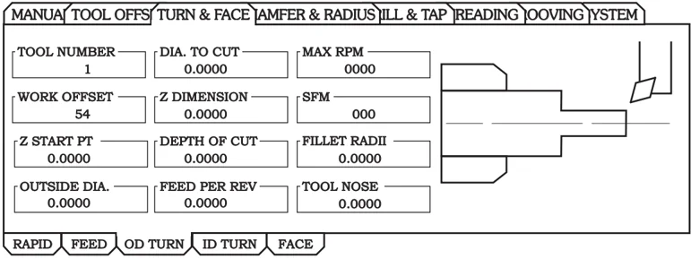
System Mode
The System Mode screens are set up to show the user current alarms, an alarm history, an alarm viewer and write display messages. In addition the "Recorder" feature is in this group.
Turning the Option On and Off
The IPS option is toggled off and on using parameter 315 bit 31 (Intuitive Prog Sys). Lathes with the option can be returned to the traditional Haas program displays by turning this parameter bit to 0.
To do this, Press the PARAM/DGNOS button. Enter "315" and press the down arrow. Use the left and right arrow, or jog handle to scroll to the last parameter bit (Intuitive Prog Sys). Press the Emergency Stop Button, type "0" (zero) and press enter.
To re-activate the IPS option, scroll to the parameter bit as previously described, press the Emergency Stop button, type "1" and press Enter. You will need the activation code; see the parameter list that shipped with the machine or contact your dealer.
AUXILIARY AXIS CONTROL
An additional external positioning axis may be added to the directly controlled axes. This axis, V, may be commanded directly from the program, but are only allowed in a G00 or G01 block. Connection of these axes is done through the second RS-232 port to a Haas single axis control. Setting 38 is used to select the number of auxiliary axes (0 or 1). The machine position display will show the present position of this axis.
There are no work offsets for this axis, so all commands are in the machine coordinate system; but if a displaced zero position has been entered into the Haas servo control, that position will be used as zero. On power-up of the CNC, the auxiliary axis control will also be initialized. To set a displaced zero, you must jog the single axis control to a new zero position and then press and hold the Clear key on the single axis control.
If a feed (G01) is programmed, the feed rate programmed in the CNC is sent to the auxiliary control without any changes. For a V-axis feed at F30.0, this means that the V-axis will move at 30 degrees per second. A G00 motion will move the axis at its maximum feed rate.
The Feed Hold and Reset buttons will not stop the auxiliary axis. Emergency Stop and Single Block will stop an auxiliary axis. When the CNC control is waiting for an auxiliary axis motion to complete, the bottom of the screen will display "V FIN". The Reset button will terminate any "hung-up" auxiliary axis communication.
The cable connecting the CNC to the single-axis control must be a DB-25 cable (male lead on both ends) and must wire pins 1, 2, 3, and 7 directly from the second (lower) serial port of the CNC to the servo control.
TAILSTOCK
The optional Tailstock (not field installable) is a hydraulically actuated cast iron member which runs along two linear guides. The 20 inches (33 1/2 inches on SL-30, 44 inches on the SL-40) of travel allows a long part to be machined. Tailstock motion is controlled through program code, in jog mode, or by a foot switch (also see "SL-10 Tailstock Operation" at the end of this section).
The tailstock is designed to travel to position at 2 rates. High pressure is called "rapid" and can be programmed with G00. Low pressure is called "feed" and can be programmed with G01. It is used to hold the part. An F code is required for feed mode (even if previously invoked) but it does not affect the actual feed rate.
Recommended hydraulic tailstock operating pressure is 120 psi.
CAUTION! If tailstock hydraulic pressure is set lower than 120 psi, it may not function reliably. It is important to verify tailstock and turret clearance before operating the machine or serious damage may occur. Adjust Settings 93 and 94 as necessary. Feed Hold will not stop the hydraulic tailstock.
Setting a Restricted Zone for the Tailstock
Setting 93 (Tail ST. X Clearance) and Setting 94 (Z/TS Diff @ X Clearance) are used to ensure that the tailstock does not collide with the turret or any tools in the turret. The restriction zone is an rectangular area in the lower right hand area of the lathe's work space. The restriction zone will change so that the Z axis and tailstock maintain a proper distance from each other when below a specified X axis clearance plane. Setting 93 specifies the clearance plane and Setting 94 specifies the Z and B axis (tailstock axis) separation to maintain. If a programmed motion crosses the tailstock protected area, an alarm is generated. Keep in mind that a restricted zone is not always desired (e.g. when setting up). To cancel a enter a 0 in Setting 94 and maximum X machine travel in Setting 93.
Setting a Value for the X Clearance Plane:
- Place the control in MDI mode.
- Select the longest tool in the turret (the tool that protrudes furthest on the X-axis plane).
- Place the control in jog mode.
- Select the X-axis for jogging and move the X-axis clear of the tailstock.
- Select the tailstock (B-axis) for jogging and move the tailstock beneath the selected tool.
- Select the X-axis and approach the tailstock until the tool and tailstock are about 0.25 inches apart.
- Find the X-axis “machine” position on the display, and enter this value for Setting 93. Back away from the tool in X a small amount before entering the value in Setting 93.
Setting a Separation for Z and B Axis Below the X Clearance Plane:
- Place the control in Zero Ret and Home G28 all axes.
- Select the X-axis and move the turret in front of the tailstock center tip.
- Move the Z-axis so that the rear of the tool turret is within about 0.25 inches of the tailstock tip.
- Find the Z-axis “machine” position on the display, enter this value for Setting 94.
A properly defined restricted zone will handle most, but not all, conflicts between the turret and tailstock.
Tailstock Settings
Default values for these settings, as shipped from the factory, will prevent the tailstock from running into the tool turret, provided the tool turret is empty. You will need to change the protection settings for any job you perform to avoid turret collisions based on tooling and part size. It is recommended that you test the limits after changing these settings.
Two settings are provided for protecting the tailstock. Setting 93 (Tail St. X Clearance) and Setting 94 (Z/TS Diff @ X Clearance). These settings, when set correctly, will stop any motion that would cause the tailstock to hit the tool turret. The following figures illustrates Settings 94, 94 105, 106, and 107; see the Settings chapter for more information.
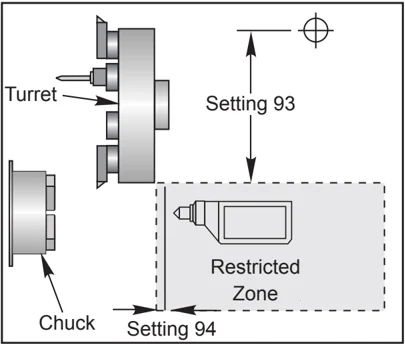
Turret Setting 93 Restricted Zone Chuck Setting 94
Tailstock Restricted Zone
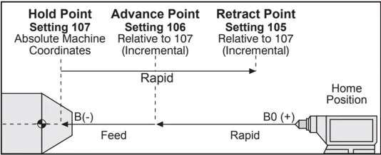
Hold Point Setting 107 Absolute Machine Coordinates Advance Point Setting 106 Relative to 107 (Incremental) Retract Point Setting 105 Relative to 107 (Incremental) Rapid B(-) Feed B0 (+) Rapid Home Position
Diagram of Settings 105, 106, and 107
Setting 93 is the X-axis machine clearance plane that the X-axis can not move below when the difference between the Z and B axes positions is less than Setting 94. When the Z- and B-axis location difference is greater than Setting 94, the X-axis is allowed to move to its travel limit. As long as the proper Z- and B-axis distance is maintained, the X-axis can move to its full travel. Likewise, if the X-axis is at its full travel, or below the clearance plane designated by Setting 93; it is not possible to reduce the Z- and B-axis difference below Setting 94.
Tailstock Foot Pedal Operation
Pressing the tailstock foot pedal will command either an M21 or M22, depending on current position. In other words, if the tailstock is left of the retract point, pressing the foot pedal will move the tailstock toward the retract point (M22). If tailstock is right of the retract point, the foot pedal will also move the tailstock toward the retract point (M22). If tailstock is at retract point, pressing the foot pedal will move the tailstock toward the hold point (M21).
If the foot pedal is pressed while tailstock is moving, the tailstock will stop and a new sequence must begin.
Jogging the Tailstock In Jog mode, the keys “TS <—” and TS “—>” are used to jog the tailstock at low pressure (feed). By selecting TS Rapid and pressing TS <— or TS —> buttons the tailstock will move at the rapid speed. The control reverts to the last jogged axis when the buttons are released
Alarms/Messages If a part is being held and tailstock motion is detected an alarm is generated. This will stop the program and turn off the spindle. This alarm is also generated if the tailstock reaches the hold point during a low pressure feed, indicating that the part has fallen out.
SL-10 Tailstock Operation The optional Haas tailstock for the SL-10 is a hydraulically actuated quill which moves within a manually positioned headstock. The tailstock is manually positioned and held in place with the lock-lever. Tailstock motion is controlled through program code, in jog mode, or by the foot switch.
The SL-10 tailstock consists of a fixed head, and a moveable center rod. Therefore, the only moving part is the tailstock center. Pressing PowerUp/Restart or AutoAll Axes will not cause the tailstock center to physically move. It is the operator’s responsibility to move it out of the way to avoid a collision. Tailstock center movement using the jog handle and remote jog handle is unavailable. The tailstock center is always considered to be at zero; as the control will not know where the tailstock center is.
SL-10 Tailstock Foot pedal Operation Pressing the foot pedal will advance or retract the foot pedal. However, pressing and holding the pedal for 5 seconds, will retract the tailstock all the way and maintain retract pressure to ensure the tailstock does not creep forward. Use this method to stow the tailstock anytime it is not in use.
The tailstock position can change over time if it is left at a position that is not fully retracted or not in contact with a part. This is due to normal hydraulic system leakage.
WARNING
- It is important to verify tailstock and turret clearance before operating machine or serious damage could occur. Adjust Setting 93, Tail ST. X Clearance and Setting 94, Z/TS Diff @ X Clearance as necessary.
- Feed Hold will not stop the hydraulic tailstock. The Emergency Stop button is the only way to stop the tailstock
Tailstock Programming M21 will cause the tailstock quill to extend toward the spindle, and M22 will cause the tailstock quill to retract away from the spindle. When an M21 is commanded, the tailstock center will be commanded to move toward the spindle and maintain continuous pressure. Note that the program will not wait while this is completed; instead, the next block will be executed immediately. A dwell should be commanded to allow the tailstock center movement to complete, or the program should be run in Single Block mode. When an M22 is commanded, the tailstock center will move away from the spindle, and then stop.
CAUTION! Do not use an M21 in the program if the tailstock is positioned manually. If this is done, the tailstock will back away from the part and then reposition against the part, which may cause the workpiece to drop.
Adjustable Tailstock The adjustable tailstock for the SL-20L and SL-30L uses two pins to attach the tailstock to the hydraulic cylinder in three different ways, creating 20.25" (SL-20L) and 30.75" (SL-30L) travels from short, medium, and long distances to the chuck.
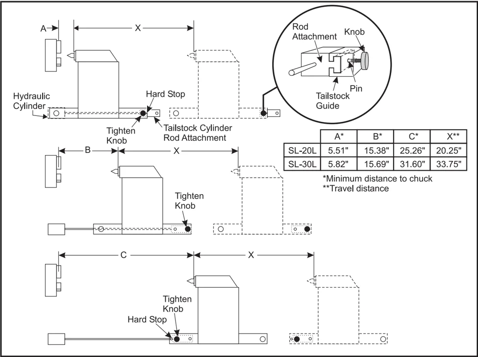
Tailstock Adjustment
- Position the tailstock at full travel to the left.
- Press Emergency Stop to turn off hydraulics and prevent accidental machine motion.
- Disengage the hydraulic cylinder attachment from the tailstock by unscrewing the knob.
- Manually slide the tailstock to align the cylinder rod attachment with the tailstock in the correct position for the desired travel range. For the shortest minimum distance to the chuck, slide the tailstock left until it hits the hard stop. For the middle minimum distance to the chuck, slide the tailstock until the right side of the tailstock guide is flush with the right side of the cylinder rod attachment. For the longest minimum distance to the chuck, slide the tailstock right until it hits the hard stop. See Illustration.
- When the cylinder attachment and pin are aligned in the desired position, engage the pin by screwing in the knob.
- Reset Emergency Stop and re-zero the tailstock to resume machine operation.
84 Programming 96-8700 rev U June 2008
PARTS CATCHER
The parts catcher is an automatic part retrieval system designed to work with bar feed applications. The parts catcher, is commanded using M Codes (M36 to activate and 37 to deactivate). The parts catcher rotates to catch finished parts and directs them into the bin mounted on the front door.
Operation
The parts catcher must be properly aligned before operation.
- Power on the machine. In MDI mode, activate the parts catcher (M36).
- Loosen the screw in the shaft collar on the outer parts catcher shaft.
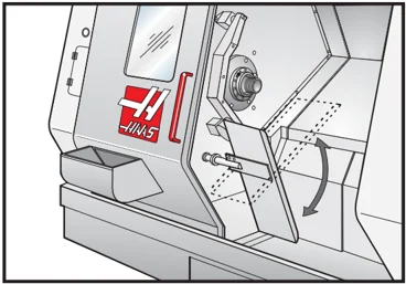
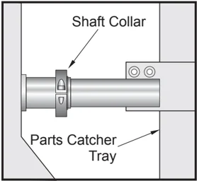
SL-20 Shaft Collar Shown
- Slide parts catcher tray into the shaft far enough to catch the part and clear the chuck. Rotate the tray to open the sliding cover of the parts collector mounted in the door and tighten the shaft collar on the part catcher shaft.
WARNING
Check the Z-axis, X-axis, tool and turret position during part catcher actuation to avoid possible collisions during operation.
Note: The operator door must be closed when actuating the part catcher.
- When programming the part catcher in a program you must use a G04 code between M53 and M63 to pause the catcher pan in the open position long enough to cut off the part and allow it to fall into the collector.
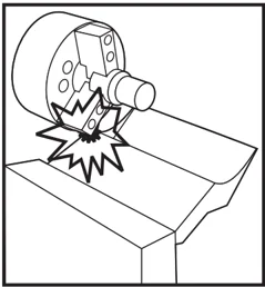
SL-10 Warning
Large chuck jaws may interfere with the operation of the parts catcher. Be sure to check the clearances before operating the parts catcher.
TOOL PRE-SETTER
The Tool Pre-Setter allows an operator to quickly set up a machine with the necessary tool and work offsets rather than having to manually record the tool offsets. Each tool has to be "touched-off" on the probe (a known point in space) to record the tool's location. When the locations are recorded, the tool's location relative to the part has to be recorded. At this point the user only has to touch-off one tool on the parts zero position, and the machine adjusts the work offsets for every tool. These tool and work offsets are used in order to tell the machine where the part is in relation to the "home" position, and how far a tool has to travel to get to the part.
When the probe is down, the machine will not allow any programs to be run and the axes can only be moved using the handle jog feature. The "Tool Offset" dimension will be recorded in the offset page under the corresponding offset number G52-G59 (G54 is typically used unless otherwise specified).
NOTE: There are up to 200 offset values available so that multiple offsets can be recorded for a single tool. In a program, an example would look like: "T417" which would select tool number 4 with offset number 17, etc.
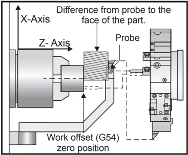
Operation
IMPORTANT: Automatic storing of the machine's position can only be performed when the jog buttons are used. Once the probe is touched, the control will beep, the turret will halt, and the position of the tool will be stored. The operator will not be able to continue jogging towards the probe. This prevents the operator from damaging the probe and ensures greater accuracy.
NOTE: If the operator jogs the tool tip into the probe too fast, the probe may slip off the tool tip.
The axis last jogged will be disabled; use the other axis to jog the turret away from the probe. All axes will then be re-enabled. If this does not work, raise the probe arm to its home position". If this is not possible, the prox switch that senses that the arm in the upright position can be activated, which will re-enable all axes, and the tool can be jogged away.
WARNING
When changing tools, always back the tool a safe distance away from the probe or you could crash the tool into the arm!
Setting Tool Geometry and Tool Shift Offsets Using the Probe
- Setting 33, Coordinate System, controls whether the current tool offsets obtained while using the tool setter are stored in Tool Geometry (FANUC) or Tool Shift (YASNAC).
- Index the turret to the tool to probe.
- Jog the tool to a safe position and lower the arm.
Touching off I.D. or O.D. Tools
- Jog the turret in the X direction until the tool tip is close to the probe (use .001" jog speed). Press the X-axis button until the tool touches the probe.
Note: Once the tool tip touches the probe, the control will beep and not allow the operator to continue jogging in that direction. When retouching a tool, Setting 64 needs to be off to ignore the value on G54.
IMPORTANT! The jog buttons must be used to automatically store the position of the tool. The jog handle can also be used; however, the values will have to be manually entered into the control.
- Next, jog the tool in the Z direction until it touches the probe. That value is then stored in the Offsets page.
Touching off Drills, Taps or Center Cutting Tools
-
Index the turret to the tool to probe.
-
Jog the tool in the Z direction until it touches the probe (Use .001" jog speed). That value is then stored in the selected Z-axis tool offset.
Setting Work Zero Offsets
Before running your program, the machines Work Zero Offsets (G52-129) must be entered.
-
In the Offsets page, select the desired work offset.
-
Index the turret to the desired tool and touch off the face of the part.
-
Press Z Face Mesur to reference the rest of the tools to the face of the part.
Lathe Tool Pre-setter Alignment
-
Install a turning tool in the tool 1 station of the tool turret and clamp a piece of material in the spindle to be able to turn a diameter on the material.
-
Use the turning tool in station 1 to take a small cut on the diameter of the material clamped in the spindle.
-
Jog the turning tool away from the part in the Z-axis only - do not jog the X-axis away from the diameter. The tool position is needed to set the geometry offset for the tool in station 1 using the X Diameter Measure Button.
-
Measure the diameter of the cut made on the work piece with a micrometer and press the X DIA MEASURE button – enter the diameter that was measured.
-
Write down the Geometry Offset for tool number 1. Go to the settings page and change setting 59 and 63 to 0 (zero).
-
Pull down the Tool Pre-setter and touch tool #1 to the probe. Subtract the new Geometry Offset value for tool 1 from the Offset value you had written down previously. Enter this value into setting 59.
-
Measure the tool probe width and multiply it by two. Subtract that value from Setting #59, and enter this new value into setting 60 (X- probe offset).
-
Enter 0 (zero) for setting 61. The value for setting 62 is the probe width as a negative number and setting 63 is the probe width as a positive number.
Once the tool probe is properly aligned, the values from X Dia Measure and the value from the probe will be the same.
EDIT MODE
Edit gives the user the ability to edit programs using popup menus.
Press the EDIT key to enter edit mode. Two editing panes are available; an active program pane and an inactive program pane. Switch between the two by pressing the EDIT key.
To edit a program, enter the program name (Onnnnn) from the active program pane and press SELECT PROG; the program will open in the active window. Pressing the F4 button will open another copy of that program in the inactive program pane if there is not a program there already. You can also select a different program in the inactive progam pane by pressing SELECT PROG from the inactive program pane and selecting the program from the list. Press F4 to exchange the programs between the two panes (make the active program inactive and vice versa). Use the jog handle or the down/up arrows buttons to scroll through the program code.
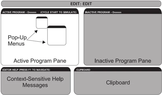
Basic Edit Mode Layout
Press F1 to access the Popup Menu. Use the Left and Right cursor arrow keys to select from the topic menu (HELP, MODIFY, SEARCH, EDIT, PROGRAM), and use the Up and Down arrow keys or handle jog to select a function. Press Enter to execute from the menu. A context-sensitive help pane in the lower left provides information on the currently selected function. Use Page Up/Down to scroll through the help message. This message also lists hotkeys that can be used for some functions.
THE PROGRAM MENU
Create New Program This menu item will create a new program. To do so, enter a program name (Onnnnn) (that is not already in the program directory) and press Enter to create the program. Hot Key - Select Prog
Select Program From List Choose this menu item to edit a program that exists in the memory.
When this menu item is selected, the programs in the control are displayed. Scroll through the list by using the cursor buttons or the jog handle. Pressing Enter or Select Prog will select the highlighted program to replace the program list with the selected program. Hot key - Select Prog
Duplicate Active Program This selection will copy the current program. The user will be prompted to enter a program (Onnnnn) number for the duplicate program.
Delete Program From List This menu item will delete a program from the program memory. Hot Key - Erase Prog
Swap Editor Programs
Puts the active program in the inactive program pane and the inactive program in the active program pane. Hot Key-F4
Switch To Left Or Right Side
This will switch between the active and inactive program for editing. Inactive and active programs remain in their respective panes. Hot Key - Edit
THE EDIT MENU
Undo
The last edit operation will be undone, up to the last 9 editing operations. Hot Key - Undo
Select Text
This menu item will select lines of program code to set the start point of the text selection. Then use the cursor keys, home, end, page up/down, or the jog handle to scroll to the last line of code to be selected and Press F2 or Write/Enter. The selected text will be highlighted. To deselect the block, press Undo. Hot Key - F2 to begin selection, F2 or Write to end selection
Move Selected Text
This feature works with the "Select Text" feature. Scroll the cursor arrow to desired part of code and press the Write/Enter button to move the selected text to its new location. The selected text will be moved to the point following the cursor (>).
Copy Selected Text
To select text, scroll the cursor arrow (>) to a portion of text and press the Write/Enter button. The text copied will be highlighted. Scroll the cursor arrow to the part of text you want to insert the copied text into. Press F2 or Write/Enter to insert the copied text to the point following the cursor (>). Hot Key - Select Text, Position Cursor and Press Write
Delete Selected Text
To select text, scroll the cursor arrow (>) to a portion of text and press the Write/Enter button. The text copied will be highlighted. Once highlighted, press the Write/Enter button to delete the text. If no block is selected, the currently highlighted item is deleted.
Cut Selection To Clipboard
All selected text will be moved from the current program to a new program called the clipboard. Any previous contents of the clipboard are deleted.
Copy Selection To Clipboard
All selected text will be copied from the current program to a new program called the clipboard. Any previous contents of the clipboard are deleted.
Paste From Clipboard
The contents of the clipboard are copied into the current program at the line following the current cursor position.
THE SEARCH MENU
Find Text This menu item will search for text or program code in the current program.
Find Again This menu item will search again for the same program code or text.
Find And Replace Text This menu item will search the current program for specific text or program and optionally replace each (or all) with another G-Code item.
THE MODIFY MENU
Remove All Line Numbers This menu item will automatically remove all unreferenced N-Codes (line numbers) from the edited program. If a group of lines is selected only these lines will be affected.
Renumber All Lines This menu item will either renumber all selected blocks in the program or, if a group of lines is selected the renumber feature will affect those lines only.
Renumber By Tool Searches for T (tool) codes, highlights all the program code up to the next T code and renumbers the N code (line numbers) in the program code.
Reverse + & - Signs This menu item will reverse the signs of the numeric values. Press the enter key to start the process and then enter the axes (e.g. X, Y, Z etc.) that is to change. When using this feature be cautious if your program contains a G10 or G92 (See the G Code section for a description).
Reverse X & Y This feature will change X address codes in the program to Y address codes and Ys to Xs.
OTHER KEYS
INSERT INSERT can be used to copy selected text in a program to the line after where you place the cursor arrow point.
ALTER ALTER can be used move selected text in a program to the line after where you place the cursor arrow point.
DELETE DELETE can be used to delete selected text in a program.
UNDO If a block has been selected, pressing undo will simply exit a block definition.
VISUAL QUICK CODE
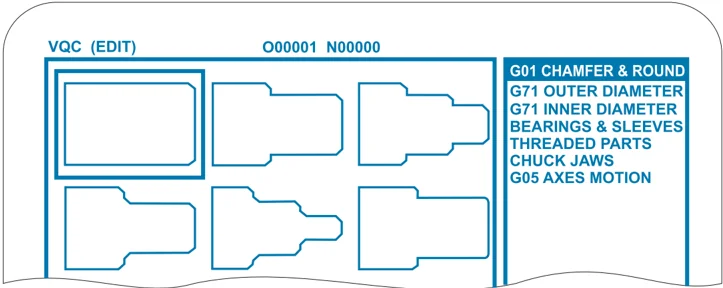
To start Visual Quick Code (VQC), press MDI/DNC, then PROGRM CONVRS. Select VQC from the tabbed menu.
Selecting a Category
Use the arrow keys to select the parts category whose description closely matches the desired part and press Write. A set of illustrations of the parts in that category will appear.

Selecting a Part Template Use the arrow keys to select a template on the page. Pressing Write will display an outline of the part and wait for the programmer to enter values to make the selected part.
Entering the Data
The control will prompt the programmer for information about the selected part. Once the information is entered, the control asks where the G-code is to be placed:
-
Select/Create a Program – A window will open prompting the user to select a program name. Highlight the program and press Write. This will add the new lines of code to the selected program. If the program already contains code, VQC enter the lines of code to the beginning of the program; before the existing code. The user also has the option to create a new program by entering a program name and by pressing Write, to will add the lines of code to the new program.
-
Add to Current Program – The code generated by VQC will be added after the cursor.
-
MDI – The code will output to MDI. Note that anything in MDI will be overwritten.
-
Cancel – The window will close and the program values will be displayed.
NOTE: The program will also be available for editing in Edit mode. It is a good idea to check the program by running it in Graphics mode.
92 Quick Code 96-8700 rev U June 2008
MACROS (OPTIONAL)
This control feature is optional; call your dealer for information.
I NTRODUCTION
Macros add capabilities and flexibly to the control that are not possible with standard G-code. Some possible uses are families of parts, custom canned cycles, complex motions, and driving optional devices.
A Macro is any routine/subprogram that may be run multiple times. A macro statement can assign a value to a variable or read a value from a variable, evaluate an expression, conditionally or unconditionally branch to another point within a program, or conditionally repeat some section of program.
Here are a few examples of the applications for Macros. Rather than give macro code here, we will outline the general applications for which Macros may be used.
Simple Patterns that are Repeated Over and Over Again in the Shop - Patterns that recur over and over again can be defined using macros and stored. For example:
- Family of parts
- Soft jaw machining
- User defined "canned" cycles (such as custom grooving cycles)
Automatic Offset Setting Based on the Program - With macros, coordinate offsets can be set in each program so that setup procedures become easier and less error-prone.
Probing - Probing enhances the capabilities of the machine in many ways. Below is just a hint of the possibilities.
- Profiling of a part to determine unknown dimensions for later machining.
- Tool calibration for offset and wear values.
- Inspection prior to machining to determine material allowance on castings.
Useful G and M Codes
M00, M01, M30 - Stop Program G04 - Dwell G65 Pxx - Macro subprogram call. Allows passing of variables. M96 Pxx Qxx - Conditional Local Branch when Discrete Input Signal is 0 M97 Pxx - Local Sub Routine Call M98 Pxx - Sub Program Call M99 - Sub Program Return or Loop G103 - Block Lookahead Limit. No cutter comp allowed M109 - Interactive User Input (see "M Codes" section)
Settings
There are 3 settings that can affect macro programs (9000 series programs), these are 9xxxx progs Lock (#23), 9xxx Progs Trace (#74) and 9xxx Progs Single BLK (#75).
Lookahead
Look ahead is an issue of great importance to the macro programmer. The control will attempt to process as many lines as possible ahead of time in order to speed up processing. This includes the interpretation of macro variables. For example,
#1101 = 1 G04 P1. #1101 = 0
96-8700 rev U June 2008 Macros 93
This is intended to turn an output on, wait 1 second, and then turn it off. However, lookahead will cause the output to turn on then immediately back off while the dwell is being processed. G103 P1 can be used to limit lookahead to 1 block. To make this example work properly, it must be modified as follows:
G103 P1 (See the G-code section of the manual for a further explanation of G103) ; #1101=1 G04 P1. ; ; ; #1101=0
Round Off
The control stores decimal numbers as binary values. As a result, numbers stored in variables can be off by 1 least significant digit. For example, the number 7 stored in macro variable #100, may later be read as 7.000001, 7.000000, or 6.999999. If your statement was, "IF [#100 EQ 7]...", it may give a false reading. A safer way of programming this would be, "IF [ROUND [#100] EQ 7]...". This issue is usually only a problem when storing integers in macro variables where you do not expect to see a fractional part later.
OPERATION NOTES
Macro variables can be saved or loaded through the RS-232, USB or the optional floppy DNC, much like settings and offsets. Refer to the Control Data Transfer section.
V ariable Display Page
The macro variables are displayed and can be modified through the current commands display. To get to the pages, press Curnt Comds and use the page up/down key.
As the control interprets a program, the variable changes are displayed on the variable display page and results can be viewed. The macro variable is set by entering a value and then pressing the Write/Enter button. Macro Variables can be cleared by pressing the Origin key. Entering the macro variable number and pressing the up/down arrow will search for that variable.
The variables displayed represent the values of the variables during the running of the program. At times, this may be up to 15 blocks ahead of the actual machine actions. Debugging a program is easier when inserting a G103 at the beginning of a program to limit block buffering, then removing it after debugging is completed.
Macro Arguments
The arguments in a G65 statement are a means of sending values to and setting the local variables of a called macro subroutine. The following two tables indicate the mapping of the alphabetic address variables to the numeric variables used in a macro subroutine.
Alphabetic Addressing
Alternate Alphabetic Addressing
| Address: | A | B | C | I | J | K | I | J | K | I | J |
|---|---|---|---|---|---|---|---|---|---|---|---|
| Variable: | 1 | 2 | 3 | 4 | 5 | 6 | 7 | 8 | 9 | 10 | 11 |
| Address: | K | I | J | K | I | J | K | I | J | K | I |
| Variable: | 12 | 13 | 14 | 15 | 16 | 17 | 18 | 19 | 20 | 21 | 22 |
| Address: | J | K | I | J | K | I | J | K | I | J | K |
| Variable: | 23 | 24 | 25 | 26 | 27 | 28 | 29 | 30 | 31 | 32 | 33 |
Arguments accept any floating point value to four decimal places. If the control is in metric, it will assume thousandths (.000). In the Example below, local variable #7 will receive .0004. If a decimal is not included in an argument value, such as: G65 P9910 A1 B2 C3, the values are passed to macro subroutines according to the following table:
Integer Argument Passing (no decimal point)
| Address: | A | B | C | D | E | F | G | H | I | J | K | L | M |
|---|---|---|---|---|---|---|---|---|---|---|---|---|---|
| Variable: | .001 | .001 | .001 | 1. | 1. | 1. | - | 1. | .0001 | .0001 | .0001 | 1. | 1. |
| Address: | N | O | P | Q | R | S | T | U | V | W | X | Y | Z |
| Variable: | - | - | - | .0001 | .0001 | 1. | 1. | .0001 | .0001 | .0001 | .0001 | .0001 | .0001 |
All 33 local macro variables can be assigned values with arguments by using the alternate addressing method. The following example shows how one could send two sets of coordinate locations to a macro subroutine. Local variables #4 through #9 would be set to .0001 through .0006 respectively.
Example: G65 P2000 I1 J2 K3 I4 J5 K6 ;
The letters G, L, N, O and P cannot be used to pass parameters to a macro subroutine.
Macro Variables
There are three categories of macro variables: system variables, global variables, and local variables. Constants are floating point values placed in a macro expression. They can be combined with addresses A...Z or they can stand alone when used within an expression. Examples of constants are .0001, 5.3 or -10.
Local Variables
Local variables range between #1 and #33. A set of local variables is available at all times. When a call to a subroutine with a G65 command is executed, the local variables are saved and a new set is available for use. This is called “nesting” of the local variables. During a G65 call, all of the new local variables are cleared to undefined values and any local variables that have corresponding address variables in the G65 line are set to the G65 line values. Below is a table of the local variables along with the address variable arguments that change them.
| Variable: | 1 | 2 | 3 | 4 | 5 | 6 | 7 | 8 | 9 | 10 | 11 |
|---|---|---|---|---|---|---|---|---|---|---|---|
| Address: | A | B | C | I | J | K | D | E | F | I | H |
| Alternate: | I | J | K | J | |||||||
| Variable: | 12 | 13 | 14 | 15 | 16 | 17 | 18 | 19 | 20 | 21 | 22 |
| Address: | K | M | J | K | I | Q | R | S | T | U | V |
| Alternate: | K | I | J | K | I | J | K | I | J | K | I |
| Variable: | 23 | 24 | 25 | 26 | 27 | 28 | 29 | 30 | 31 | 32 | 33 |
| Address: | W | X | Y | Z | K | I | J | K | I | J | K |
| Alternate: | J | K | I | J | K | I | J | K | I | J | K |
96-8700 rev U June 2008 Macros 95
Note that variables 10, 12, 14-16 and 27-33 do not have corresponding address arguments. They can be set if a sufficient number of I, J and K arguments are used as indicated above in the section about arguments. Once in the macro subroutine, the local variables can be read and modified by referencing the variable numbers 1-33.
When the L argument is used to do multiple repetitions of a macro subroutine, the arguments are set only on the first repetition. This means that if local variables 1-33 are modified in the first repetition, the next repetition will have access only to the modified values. Local values are retained from repetition to repetition when the L address is greater than 1.
Calling a subroutine via an M97 or M98 does not nest the local variables. Any local variables referenced in a subroutine called by an M98 are the same variables and values that existed prior to the M97 or M98 call.
Global Variables
Global variables are variables that are accessible at all times. There is only one copy of each global variable. Global variables occur in three ranges: 100-199, 500-699 and 800-999. The global variables remain in memory when power is turned off.
Occasionally, there have been some macros written for factory installed options that use the global variables. For example, probing, pallet changers, etc. When using global variables, be sure they are not in use by another program on the machine.
System Variables
System variables give the programmer the ability to interact with a variety of control conditions. By setting a system variable, the function of the control can be modified. By reading a system variable, a program can modify its behavior based on the value in the variable. Some system variables have a Read Only status; this means that the programmer cannot modify them. A brief table of currently implemented system variables follows with an explanation of their use.
| VARIABLES | USAGE |
|---|---|
| #0 | Not a number (read only) |
| #1-#33 | Macro call arguments |
| #100-#199 | General purpose variables saved on power off |
| #500-#599 | General purpose variables saved on power off |
| #600-#699 | General purpose variables saved on power off |
| #700-#749 | Hidden variables for internal use only |
| #750-#751 | Serial port #2 data collection |
| #800-#999 | General purpose variables saved on power off |
| #1000-#1063 | 64 discrete inputs (read only) |
| #1064-#1068 | Maximum axis loads for X, Y, Z, A, and B-axes on MOCON1 |
| #1080-#1087 | Raw analog to digital inputs (read only) |
| #1090-#1098 | Filtered analog to digital inputs (read only) |
| #1094 | Coolant Level |
| #1098 | Spindle load with Haas vector drive (read only) |
| #1100-#1139 | 40 discrete outputs |
| #1140-#1155 | 16 extra relay outputs via multiplexed output |
| #1264-#1268 | Maximum axis loads for U, V, W, SS, and TT on MOCON2 |
| #2001-#2050 | X axis tool shift offsets |
| #2101-#2150 | Z axis tool shift offsets |
| #2201-#2250 | Tool nose radius offsets |
| #2301-#2350 | Tool tip direction |
| #2401-#2450 | Tool diameter/radius offsets |
| #2601-#2650 | Tool diameter/radius wear |
| #2701-#2750 | X axis tool wear offsets |
| #2801-#2850 | Z axis tool wear offsets |
| #2901-#2950 | Tool nose radius wear offsets |
96 Macros 96-8700 rev U June 2008
#3000 Programmable alarm
#3001 Millisecond timer
#3002 Hour timer
#3003 Single block suppression
#3004 Override control
#3006 Programmable stop with message
#3011 Year, month, day
#3012 Hour, minute, second
#3020 Power on timer (read only)
#3021 Cycle start timer
#3022 Feed timer
#3023 Present cycle time
#3024 Last cycle time
#3025 Previous cycle time
#3026 Tool in spindle (read only)
#3027 Spindle RPM (read only)
#3030 Single Block
#3031 Dry Run
#3032 Block Delete
#3033 Opt Stop
#3901 M30 count 1
#3902 M30 count 2
#4001-#4020 Previous block group codes
#4101-#4126 Previous block address codes
NOTE: Mapping of 4101 to 4126 is the same as the alphabetic addressing of “Macro Arguments” section; e.g. the statement x1.3 sets variable #4124 to 1.3.
#5000-#5006 Previous block end position
#5020-#5027 Present machine coordinate position
#5041-#5046 Present work coordinate position
#5061-#5069 Present skip signal position - X, Z, Y, A, B, C, U, V, W
#5081-#5086 Present tool offset
#5201-#5206 Common offset
#5221-#5226 G54 work offsets
#5241-#5246 G55 work offsets
#5261-#5266 G56 work offsets
#5281-#5286 G57 work offsets
#5301-#5306 G58 work offsets
#5321-#5326 G59 work offsets
#5401-#5500 Tool feed timers (seconds)
#5501-#5600 Total tool timers (seconds)
#5601-#5699 Tool life monitor limit
#5701-#5800 Tool life monitor counter
#5801-#5900 Tool load monitor (maximum load sensed so far)
#5901-#6000 Tool load monitor limit
#6001-#6277 Settings (read only)
#6501-#6999 Parameters (read only)
NOTE: The low order bits of large values will not appear in the macro variables for settings and parameters.
96-8700 rev U June 2008 Macros 97
Macros
| Range | Description |
|---|---|
| #7001-#7006 (#14001-#14006) | G110 (G154 P1) additional work offsets |
| #7021-#7026 (#14021-#14026) | G111 (G154 P2) additional work offsets |
| #7041-#7046 (#14041-#14046) | G114 (G154 P3) additional work offsets |
| #7061-#7066 (#14061-#14066) | G115 (G154 P4) additional work offsets |
| #7081-#7086 (#14081-#14086) | G116 (G154 P5) additional work offsets |
| #7101-#7106 (#14101-#14106) | G117 (G154 P6) additional work offsets |
| #7121-#7126 (#14121-#14126) | G118 (G154 P7) additional work offsets |
| #7141-#7146 (#14141-#14146) | G119 (G154 P8) additional work offsets |
| #7161-#7166 (#14161-#14166) | G120 (G154 P9) additional work offsets |
| #7181-#7186 (#14181-#14186) | G121 (G154 P10) additional work offsets |
| #7201-#7206 (#14201-#14206) | G122 (G154 P11) additional work offsets |
| #7221-#7226 (#14221-#14221) | G123 (G154 P12) additional work offsets |
| #7241-#7246 (#14241-#14246) | G124 (G154 P13) additional work offsets |
| #7261-#7266 (#14261-#14266) | G125 (G154 P14) additional work offsets |
| #7281-#7286 (#14281-#14286) | G126 (G154 P15) additional work offsets |
| #7301-#7306 (#14301-#14306) | G127 (G154 P16) additional work offsets |
| #7321-#7326 (#14321-#14326) | G128 (G154 P17) additional work offsets |
| #7341-#7346 (#14341-#14346) | G129 (G154 P18) additional work offsets |
| #7361-#7366 (#14361-#14366) | G154 P19 additional work offsets |
| #7381-#7386 (#14381-#14386) | G154 P20 additional work offsets |
| #14401-#14406 | G154 P21 additional work offsets |
| #14421-#14426 | G154 P22 additional work offsets |
| #14441-#14446 | G154 P23 additional work offsets |
| #14461-#14466 | G154 P24 additional work offsets |
| #14481-#14486 | G154 P25 additional work offsets |
| #14501-#14506 | G154 P26 additional work offsets |
| #14521-#14526 | G154 P27 additional work offsets |
| #14541-#14546 | G154 P28 additional work offsets |
| #14561-#14566 | G154 P29 additional work offsets |
| #14581-#14586 | G154 P30 additional work offsets |
| • | |
| • | |
| • | |
| #14781-#14786 | G154 P40 additional work offsets |
| • | |
| • | |
| • | |
| #14981-#14986 | G154 P50 additional work offsets |
| • | |
| • | |
| • | |
| #15181-#15186 | G154 P60 additional work offsets |
| • | |
| • | |
| • | |
| #15381-#15386 | G154 P70 additional work offsets |
| • | |
| • | |
| • | |
| #15581-#15586 | G154 P80 additional work offsets |
| • | |
| • | |
| • | |
| #15781-#15786 | G154 P90 additional work offsets |
| • | |
| • | |
| • | |
| 15881-15886 | G154 P95 additional work offsets |
| 15901-15906 | G154 P96 additional work offsets |
| 15921-15926 | G154 P97 additional work offsets |
| 15941-15946 | G154 P98 additional work offsets |
| 15961-15966 | G154 P99 additional work offsets |
98 Macros 96-8700 rev U June 2008