Example Using Start Thread Angle (Q)
G76 X1.92 Z-2. Q60000 F0.2 D0.01 K0.04 (60 degree cut)
G76 X1.92 Z-2. Q120000 F0.2 D0.01 K0.04 (120 degree cut)
G76 X1.92 Z-2. Q270123 F0.2 D0.01 K0.04 (270.123 degree cut)
The following rules apply to the usage of Q:
- The start angle, Q, must be specified every time it is used. If no value is specified then a zero (0) angle is assumed.
- The angle of threading increment is 0.001 degrees and it cannot have any decimal point, for example a 180° angle must be specified as Q180000 and an angle of 35° as Q35000.
- The Q angle must be entered as a positive value from 0 to 360000.
Multiple Start Threading Example
Multiple threads can be cut by changing the start point for each threading cycle.
The previous example has been modified to now create a multiple start thread. To calculate the additional start points the feed (F0.0714) is divided by the number of start points (3) .0714 / 3 = .0238. This value is then added to the initial Z-axis start point (line 2) in order to calculate the next start point (line 4). Add the same amount again to the previous start point (line 4) to calculate the next start point (line 6).
(1) M08
(2) G00 X1.1 Z0.5 (Initial Start Point)
(3) G76 X0.913 Z-0.85 K0.042 D0.0115 F0.0714 (Threading cycle)
(4) G00 X1.1 Z0.5238 (Next Start Point [.5 + .0238 = 5.238])
(5) G76 X0.913 Z-0.85 K0.042 D0.0115 F0.0714 (Threading cycle)
(6) G00 X1.1 Z0.5476 (Last Start Point [.5238 + .0238 = 5.476])
(7) G76 X0.913 Z-0.85 K0.042 D0.0115 F0.0714 (Threading cycle)
G77 Flattening Cycle (This G-code is optional and is used for live tooling) (Group 00)
(Also see the C-axis section)
NOTE: This cycle is only available on lathes with the live tooling option.
- I Angle of first flat, in degrees.
J Distance from center to flat. - L Number of flat surfaces to cut
R Tool Radius - S Spindle Speed
- K Part Diameter
- indicates optional
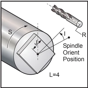
G77 with L specified
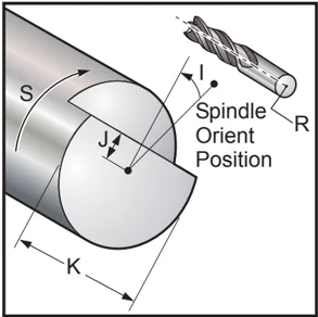
G77 with K specified
The G77 canned cycle can be used to create one or more flat surfaces on a round part.
G77 operates in one of two modes, depending on whether a K code or an L code is specified. If a K code is specified, one flat surface will be cut. If an L code is specified, L flat surfaces will be cut, equally spaced all the way around the part. L must be greater than or equal to 3. If two sides are desired, perform two K cuts at I angle spacing.
The J value specifies the distance from the center of the part to the center of a flat surface. Specifying a larger distance will result in a shallower cut. This may be used to perform separate roughing and finishing passes. When using an L code, care should be taken to verify that the corner to corner size of the resulting part is not smaller than the diameter of the original part, or the tool may crash into the part during its approach.
The S value specifies the rpm speed that the spindle will maintain during the flatting cycle. The default value is 6. Higher values will not affect the flatness, but will affect the position of the flats. To calculate the maximum error in degrees, use RPM * .006.
The L value allows a part with multiple flat surfaces to be specified. For example, L4 specifies a square, and L6 specifies a hex.
The I value specifies the offset of the center of the first flat surface from the zero position, in degrees. If the I value is not used, the first flat surface will start at the zero position. This is equivalent to specifying an I equal to half the number of degrees covered by the flat surface. For example, a square cut without an I value would be the same as a square cut with I set to 45.
Flatting Examples with G77:
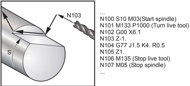
Cut a half-inch deep flat into the top inch of a part that is four inches in diameter, using a tool one inch in diameter:

... N100 S10 M03(Start spindle) N101 M133 P1000 (Turn live tool) N102 G00 X6.1 N103 Z-1. N104 G77 J1.5 K4. R0.5 N105 Z1. N106 M135 (Stop live tool) N107 M05 (Stop spindle) ...
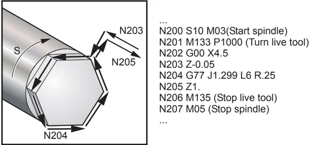
Cut a hexagon into the top half inch of a part that is three inches in diameter, using a tool 1/2" in diameter.
... N200 S10 M03(Start spindle) N201 M133 P1000 (Turn live tool) N202 G00 X4.5 N203 Z-0.05 N204 G77 J1.299 L6 R.25 N205 Z1. N206 M135 (Stop live tool) N207 M05 (Stop spindle) ...
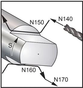
Cut a 3/8" flat into the top and bottom of a part that is two inches in diameter, using a half inch diameter tool:
96-8700 rev U June 2008 G Codes 149
%
O00015 (Sample 2 Sided Flat Program)
N100 T606
N110 G97 S3 M03
N120 M133 P2000
N130 G00 X4. Z0.05
N140 Z-1.849
N150 G77 J0.625 I0 R0.25 K2.
(J=1.25 Flat Dia, I0=flat center, R.25=.5 dia end-mill, K=part stock dia)
N160 G77 J0.625 I180. R0.25 K2.
(J=1.25 flat dia, I180.=flat center, R.25=.5 dia end-mill, K=part stock dia)
N170 G00 Z1.
N180 M135
N190 M05
N200 G00 X10. Z12.
N210 M30
%
G80 Canned Cycle Cancel (Group 09*)
This G code is modal in that it deactivates all canned cycles. Note that use of G00 or G01 will also cancel a canned cycle.
G81 Drill Canned Cycle (Group 09)
| F | Feed Rate |
|---|---|
| *L | Number of repeats |
| R | Position of the R plane |
| *W | Z-axis incremental distance |
| *X | Optional X-axis motion command |
| *Z | Position of bottom of hole |
- indicated optional
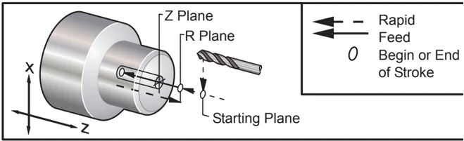
G81 Drill Canned Cycle
G82 Spot Drill Canned Cycle (Group 09)
| F | Feed Rate |
|---|---|
| *L | Number of repeats |
| P | The dwell time at the bottom of the hole |
| R | Position of the R plane |
| W | Z-axis incremental distance |
| *X | X-axis motion command |
| *Z | Position of bottom of hole |
- indicates optional
This G code is modal in that it activates the canned cycle until it is canceled or another canned cycle is selected. Once activated, every motion of X will cause this canned cycle to be executed.
150 G Codes 96-8700 rev U June 2008
 G82 Spot Drill Canned Cycle
G83 Normal Peck Drilling Canned Cycle (Group 09)
F Feed Rate *I size of first cutting depth *J amount to reduce cutting depth each pass *K minimum depth of cut *L Number of repeats *P The dwell time at the bottom of the hole *Q The cut-in value, always incremental R Position of the R plane *W Z-axis incremental distance *X X-axis motion command *Z Position of bottom of hole * indicates optional
 G83 Peck Drilling Canned Cycle
Programming Notes: If I, J, and K are specified, a different operating mode is selected. The first pass will cut in the value of I, each succeeding cut will be reduced by amount J, and the minimum cutting depth is K. Do not use a Q value when programming with I,J,K.
Setting 52 changes the way G83 works when it returns to the R plane. Usually the R plane is set well outside the cut to insure that the chip clearing motion allows the chips to clear the hole, but this causes a wasted motion when first drilling through this "empty" space. If Setting 52 is set to the distance required to clear chips, the R plane can be put much closer to the part being drilled. When the clear move to R occurs, the Z will be moved past R by this value in setting 52.
Setting 22 is the amount to feed in Z to get back the same point at which the retraction occurred.
96-8700 rev U June 2008 G Codes 151
G84 Tapping Canned Cycle (Group 09)
F Feed Rate R Position of the R plane *W Z-axis incremental distance *X X-axis motion command *Z Position of bottom of hole
* indicates optional
Programming Notes: It is not necessary to start the spindle CW before this canned cycle. The control does this automatically.
The feed rate for tapping is the lead of the thread. This is found by dividing 1 by the number of threads. Example: 20 pitch 1/20 = .05 Feedrate 18 pitch 1/18 = .0555 Feedrate 16 pitch 1/16 = .0625 Feedrate
For Metric taps, divide the pitch by 25.4 Example: M6 x 1 = F.03937 M8 x 1.25 = F.0492
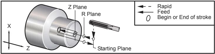
G84 Tapping Canned Cycle
G85 Boring Canned Cycle (Group 09)
F Feed Rate *L Number of repeats R Position of the R plane *U X-axis incremental distance *W Z-axis incremental distance *X X-axis motion command *Z Position of bottom of hole
* indicates optional
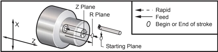
G85 Boring Canned Cycle
G86 Bore and Stop Canned Cycle (Group 09)
F Feed Rate *L Number of repeats R Position of the R plane *U X-axis incremental distance *W Z-axis incremental distance *X X-axis motion command *Z Position of bottom of hole * indicates optional
Programming Note: The spindle will stop once the tool reaches the bottom of the hole. The tool will be retracted once the spindle has stopped.
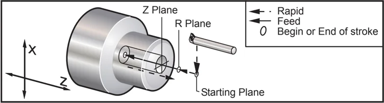
G86 Bore & Stop Canned Cycle
G87 Bore and Manual Retract Canned Cycle (Group 09)
F Feed Rate *L Number of repeats R Position of the R plane *U X-axis incremental distance *W Z-axis incremental distance *X X-axis motion command *Z Position of bottom of hole * indicates optional
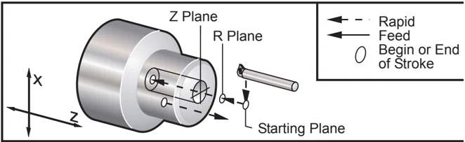
G87 Bore & Manual Retract Canned Cycle
96-8700 rev U June 2008 G Codes 153
G88 Bore and Dwell and Manual Retract Canned Cycle (Group 09)
F Feed Rate *L Number of repeats P The dwell time at the bottom of the hole R Position of the R plane *U X-axis incremental distance *W Z-axis incremental distance *X X-axis motion command *Z Position of bottom of hole
- indicates optional
Programming Note: The tool will dwell at the bottom of the hole for the value of P, then the spindle stop. The tool will need to be retracted manually.
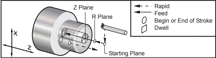
G88 Bore, Dwell & Manual Retract Canned Cycle
G89 Bore and Dwell Canned Cycle (Group 09)
F Feed Rate *L Number of repeats P The dwell time at the bottom of the hole R Position of the R plane *U X-axis incremental distance *W Z-axis incremental distance *X X-axis motion command *Z Position of bottom of hole
- indicates optional
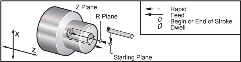
G89 Bore & Dwell Canned Cycle
G90 O.D./I.D. Turning Cycle (Group 01)
F(E) Feed rate
- I Optional distance and direction of X axis taper, radius
- U X-axis incremental distance to target, diameter
- W Z-axis incremental distance to target X X-axis absolute location of target Z Z-axis absolute location of target
- indicates optional
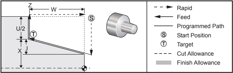
G90 is used for simple turning, however, multiple passes are possible by specifying the X locations of additional passes.
Straight turning cuts can be made by specifying X, Z and F. By adding an I value, a taper cut can be made. The amount of taper is referenced from the target. That is, I is added to the value of X at the target.
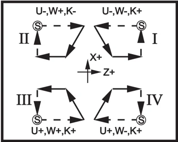
Any of the four ZX quadrants can be programmed using U, W, X, and Z; the taper can be positive or negative. The following figure gives a few examples of the values required for machining in each of the four quadrants.
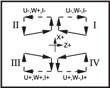
G90-92 Address Relationships
G92 Threading Cycle (Group 01)
F(E) Feed rate, the lead of the thread
- I Optional distance and direction of X axis taper, radius
- Q Start Thread Angle
- U X-axis incremental distance to target, diameter
- W Z-axis incremental distance to target X X-axis absolute location of target Z Z-axis absolute location of target
- indicates optional
Programming Notes: Setting 95 / 96 determine chamfer size / angle M23 / 24 turn chamfering on/off.
G92 is used for simple threading, however, multiple passes for threading are possible by specifying the X locations of additional passes. Straight threads can be made by specifying X, Z and F. By adding an I value, a pipe or taper thread can be cut. The amount of taper is referenced from the target. That is, I is added to the value of X at the target. At the end of the thread, an automatic chamfer is cut before reaching the target; default for this chamfer is one thread at 45 degrees. These values can be changed with Setting 95 and Setting 96.
During incremental programming, the sign of the number following the U and W variables depends on the direction of the tool path. For example, if the direction of a path along the X-axis is negative, the value of U is negative.
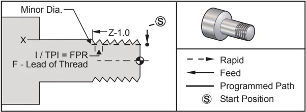
G92 Threading Cycle
Program Example
% T101 G50 S3000 M3 G97 S1000 X1.2 Z.2 G92 X.980 Z-1.0 F.0833 2nd pass X.965 3rd pass X.955 4th pass X.945 5th pass X.935 6th pass X.925 7th pass X.917 8th pass X.910 9th pass X.905 10th pass X.901 11th pass X.899 %
Description
(1”-12 Thread Cutting Program)
(Rapid to Clear position)
(Set up Threading cycle)
(Subsequent Passes)
"
"
"
"
"
"
"
"
(Subsequent Passes)
Example Using Start Thread Angle Q
G92 X-1.99 Z-2. Q60000 F0.2; (60 degree cut) G92 X-1.99 Z-2. Q120000 F0.2; (120 degree cut) G92 X-1.99 Z-2. Q270123 F0.2; (270.123 degree cut)
The following rules apply to the usage of Q:
- The start angle, Q, must be specified every time it is used. If no value is specified then a zero (0) angle is assumed.
- The angle of threading increment is 0.001 degrees. Do not use a decimal point in the entry; for example, a 180° angle must be specified as Q180000 and an angle of 35° as Q35000.
- The Q angle must be entered as a positive value from 0 to 360000.
In general, when multi-threads are being performed it is a good practice to achieve the depth of the threads at a uniform level across all the threading angles. One way to achieve this is to make a sub-program that will only cause the Z-axis to move for the different angles of threading. After the sub-program has finished change the X-axis depth and call the sub-program again.
G94 End Facing Cycle (Group 01)
F(E) Feed rate
- K Optional distance and direction of Z axis coning
- U X-axis incremental distance to target, diameter
- W Z-axis incremental distance to target X X-axis absolute location of target Z Z-axis absolute location of target
- indicates optional

G94 End Face Turning Cycle
Straight end facing cuts can be made by just specifying X, Z and F. By adding K a cone-shaped face can be cut. The amount of coning is referenced from the target. That is K is added to the value of X at the target.
Any of the four ZX quadrants can be programmed by varying U, W, X, and Z. The coning can be positive or negative. The following figure gives a few examples of the values required for machining in each of the four quadrants.
During incremental programming, the sign of the number following the U and W variables depends on the direction of the tool path. If the direction of a path along the X-axis is negative, the value of U is negative.
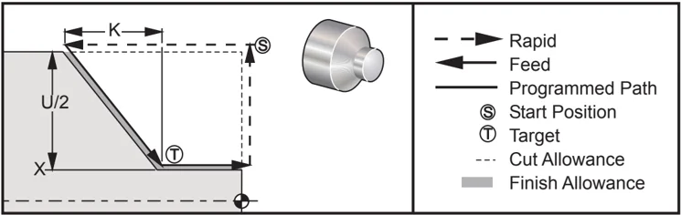
G94 Address Relationships
G95 Live Tooling Rigid Tap (Face) (Group 09)
F Feed Rate R Position of the R plane W Z-axis incremental distance X Optional Part Diameter X-axis motion command Z Position of bottom of hole
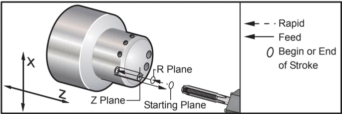
G95 Live Tooling Rigid Tapping is similar to G84 Rigid Tapping in that it uses the F, R, X and Z addresses, however, it has the following differences:
- The main spindle must be clamped (use M14) before G95 is commanded.
- The control must be in G99 Feed per Revolution mode in order for tapping to work properly.
- An S (spindle speed) command must have been issued prior to the G95.
- The X axis must be positioned between machine zero and the center of the main spindle, do not position beyond spindle center.
% O00800 N1 T101 (Axial 1/4-20 Tap) G99 (Neccesary or This Cycle) G00 Z0.5 X2.5 S500 (RPM Should Look Like This, CW Direction) M19PXX (Orient Spindle at Desired Location) M14(Clamp Spindle) G95 Z-.500 R.25 F0.05 (Thread Down .50 Deep) G28 U0 G28 W0 M135 (Stop Live Tooling Spindle) M15 (Unlock Spindle) M30 %
G96 Constant Surface Speed ON (Group 13)
This commands the control to maintain a constant cutting speed. This means the spindle speed increases as the workpiece gets smaller. Surface speed is based on the distance of the tool tip to the spindle center (radius of cut). The current S code is used to determine the surface speed. The value of S indicates inches per revolution of the spindle when Setting 9 is set to Inch, while S indicates millimeters per revolution of the spindle when Setting 9 is set to Metric.
G97 Constant Surface Speed OFF (Group 13)
This commands the control to NOT adjust the spindle speed based on the radius of cut and used to cancel any G96 command. When G97 is in effect, any S command is revolution per minute (RPM).
G98 Feed Per Minute (Group 10)
This command changes how the F address code is interpreted. The value of F indicates inches per minute when Setting 9 is set to Inch, and F indicates millimeters per minute when Setting 9 is set to Metric.
G99 Feed Per Revolution (Group 10)
This command changes how the F address is interpreted. The value of F indicates inches per revolution of the spindle when Setting 9 is set to Inch, while F indicates millimeters per revolution of the spindle when Setting 9 is set to Metric.
G100 Disable Mirror Image (Group 00)
G101 Enable Mirror Image (Group 00)
X Optional X-axis command
Z Optional Z-axis command
At least one is required.
Programmable mirror image can be turned on or off individually for the X and/or Z axis. The bottom of the screen will indicate when an axis is mirrored. These G codes should be used in a command block without any other G codes and will not cause any axis motion. G101 will turn on mirror image for any axis listed in that block. G100 will turn off mirror image for any axis listed in the block. The actual value given for the X or Z code has no effect; G100 or G101 by itself will have no effect. For example, G101 X 0 turns on X-axis mirror. Note that settings 45 through 48 may be used to manually select mirror image.
G102 Programmable Output to RS-232 (Group 00)
*X X-axis command
*Z Z-axis command
- indicates optional
Programmable output to the first RS-232 port send the current work coordinates of the axes to another computer. Use this G code in a command block without any other G codes; it will not cause any axis motion.
Programming note: Optional spaces (Setting 41) and EOB control (Setting 25) are applied.
Digitizing of a part is possible using this G code and a program which steps over a part in X-Z and probes across in Z with a G31. When the probe hits, the next block could be a G102 to send the X and Z position out to a computer which could store the coordinates as a digitized part. Additional software for the personal computer is required to complete this function.
G103 Limit Block Lookahead (Group 00)
Maximum number of blocks the control will look ahead (Range 0-15), for example: G103 [P.]
This is commonly referred to, as “Block Look-ahead”, and describes what the control is doing in the background during machine motions. The control prepares future blocks (lines of code) ahead of time. While the current block is executing, the next block has already been interpreted and prepared for continuous motion.
When G103 P0 is programmed, block limiting is disabled. Block limiting is also disabled if G103 appears in a block without a P address code. When G103 Pn is programmed, look-ahead is limited to n blocks.
G103 is also useful for debugging macro programs. Macro expressions are done during look-ahead time. For example, by inserting a G103 P1 into the program, macro expressions will be performed one block ahead of the currently executing block.
G105 Servo Bar Command
Bar Feed Command. See the Haas bar feeder manual.
G110,G111 and G114-G129 Coordinate System (Group 12)
These codes select one of the additional user coordinate systems. All subsequent references to axes positions will be interpreted in the new coordinate system. Operation of G110 to G129 are the same as G54 to G59.
G112 XY to XC interpretation (Group 04)
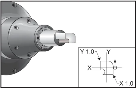
The G112 Cartesian to Polar coordinate transformation feature allows the user to program subsequent blocks in Cartesian XY coordinates, which the control automatically converts to polar XC coordinates. While it is active, G17 XY plane is used for G01 linear XY strokes and G02 and G03 for circular motion. X, Y position commands are converted into rotary C-axis and linear X-axis moves.
Note that mill-style Cutter Compensation becomes active when G112 is used. Cutter Compensation (G41, G42) must be canceled (G40) before exiting G112.
G113 G112 Cancel (Group 04)
G113 cancels the Cartesian to Polar coordinate conversion.
G112 Program Example
% G2X-.375Y-.75R.375 T0101 G1Y-1. G54 G3X-.25Y-1.125R.125 G17 G1X.75 G112 G3X.875Y-1.R.125 M154 G1Y0. G0G98Z.1 G0Z.1 G0X.875Y0. G113 M8 G18 G97P2500M133 M9 G1Z0.F15. M155 Y.5F5. M135 G3X.25Y1.125R.625 G28U0. G1X-.75 G28W0.H0. G3X-.875Y1.R.125 M30 G1Y-.25 % G3X-.75Y-.375R.125
G154 Select Work Coordinates P1-99 (Group 12)
This feature provides 99 additional work offsets. G154 with a P value from 1 to 99 will activate the additional work offsets. For example G154 P10 will select work offset 10 from the list of additional work offset. Note that G110 to G129 refer to the same work offsets as the G154 P1 through P20; they can be selected by using either method. When a G154 work offset is active, the heading in the upper right work offset will show the G154 P value.
G154 work offsets format
#14001-#14006 G154 P1 (also #7001-#7006 and G110) #14021-#14026 G154 P2 (also #7021-#7026 and G111) #14041-#14046 G154 P3 (also #7041-#7046 and G112) #14061-#14066 G154 P4 (also #7061-#7066 and G113) #14081-#14086 G154 P5 (also #7081-#7086 and G114) #14101-#14106 G154 P6 (also #7101-#7106 and G115) #14121-#14126 G154 P7 (also #7121-#7126 and G116) #14141-#14146 G154 P8 (also #7141-#7146 and G117) #14161-#14166 G154 P9 (also #7161-#7166 and G118) #14181-#14186 G154 P10 (also #7181-#7186 and G119) #14201-#14206 G154 P11 (also #7201-#7206 and G120) #14221-#14221 G154 P12 (also #7221-#7226 and G121) #14241-#14246 G154 P13 (also #7241-#7246 and G122) #14261-#14266 G154 P14 (also #7261-#7266 and G123) #14281-#14286 G154 P15 (also #7281-#7286 and G124) #14301-#14306 G154 P16 (also #7301-#7306 and G125) #14321-#14326 G154 P17 (also #7321-#7326 and G126) #14341-#14346 G154 P18 (also #7341-#7346 and G127) #14361-#14366 G154 P19 (also #7361-#7366 and G128) #14381-#14386 G154 P20 (also #7381-#7386 and G129) #14401-#14406 G154 P21 #14421-#14426 G154 P22 #14441-#14446 G154 P23 #14461-#14466 G154 P24 #14481-#14486 G154 P25 #14501-#14506 G154 P26 #14521-#14526 G154 P27 #14541-#14546 G154 P28
160 G Codes 96-8700 rev U June 2008
#14561-#14566 G154 P29 #14581-#14586 G154 P30 #14781-#14786 G154 P40 #14981-#14986 G154 P50 #15181-#15186 G154 P60 #15381-#15386 G154 P70 #15581-#15586 G154 P80 #15781-#15786 G154 P90 #15881-#15886 G154 P95 #15901-#15906 G154 P96 #15921-#15926 G154 P97 #15941-#15946 G154 P98 #15961-#15966 G154 P99
G159 Background Pickup / Part Return
Automatic Parts Loader (APL) Command. See the Haas APL manual.
G160 APL Axis Command Mode On
Automatic Parts Loader Command. See the Haas APL manual.
G161 APL Axis Command Mode Off
Automatic Parts Loader Command. See the Haas APL manual.
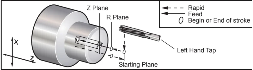
G184 Reverse Tapping Canned Cycle For Left Hand Threads (Group 09)
F Feed Rate in inches (mm) per minute R Position of the R plane *W Z-axis incremental distance (optional) *X X-axis motion command (optional) *Z Position of bottom of hole (optional)
Programming Notes: When tapping, the feedrate is the lead of the thread. See example of G84. It is not necessary to start the spindle CCW before this canned cycle; the control does this automatically.
G184 Tapping Canned Cycle
96-8700 rev U June 2008 G Codes 161
G186 Rev Live Tool Rig Tap (Group 09) F Feed Rate R Position of the R plane W Z-axis incremental distance X Optional Part Diameter X-axis motion command Z Position of bottom of hole
G95 / G186 Live Tooling Rigid Tapping (Face)
it is not necessary to start the spindle CW before this canned cycle; the control does this automatically.
The feed rate for tapping is the lead of the thread. This is found by dividing 1 by the number of threads. Example: 20 pitch 1/20 = .05 Feedrate 18 pitch 1/18 = .0555 Feedrate 16 pitch 1/16 = .0625 Feedrate
For Metric taps, divide the pitch by 25.4 Example: M6 x 1 = F.03937 M8 x 1.25 = F.0492
G187 Accuracy Control (Group 00) Programming G187 is as follows: G187 E0.01 (to set value) G187 (to revert to setting 85 value)
The G187 code is used to select the accuracy with which corners are machined. The form for using G 187 is G187 Ennnn, where nnnn is the desired accuracy.
G195 Live Tool Radial Tapping (Diameter) (Group 00) F Feed Rate per revolution (G99) R Position of the R plane *U X-axis incremental distance *X X-axis motion command *Z Position of bottom of hole
G196 Reverse Live Tool Vector Tapping (Diameter) (Group 00)
- F Feed Rate per revolution (G99)
- R Position of the R plane
- *U X-axis incremental distance
- *X X-axis motion command
- *Z Position of bottom of hole
These G codes perform live tooling radial or vector tapping on a lathe; they do not permit an “R” plane.
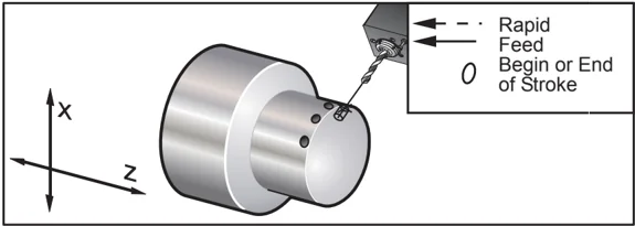
G195 / G196 Live Tooling Rigid Tapping (Diameter)
Below is a brief program example of G195
% O00800 N1 T101 (RADIAL 1/4-20 TAP) G99 (Neccesary for this cycle) G00 Z0.5 X2.5 Z-0.7 S500 (rpm should look like this, cw direction)** M19PXX (Orient spindle at desired location) M14(Lock spindle up) G195 X1.7 F0.05 (thread down to X1.7) G28 U0 G28 W0 M135 (Stop Live tooling spindle) M15 (Unlock Spindle brake) M30 %
G200 Index on the Fly (Group 00)
- U Optional relative move in X to tool change position
- W Optional relative move in Z to tool change position
- X Optional final X position
- Z Optional final Z position
- T Required tool number and offset number in standard form
This G code will cause the lathe to change tools while performing a rapid move away from and back to the part, to save time.
Example: G200 T202 U0.5 W0.5 X8. Z2.
U and W specify a relative motion in X and Z, which is performed as the tool turret unseats. X and Z specify the position to move to as the tool turret reseats. Both motions are rapid.
96-8700 rev U June 2008 G Codes 163
M CODES (MISCELLANEOUS FUNCTIONS)
M-Codes are non axes moving commands for the machine. The format for an M code is the letter "M" followed by two numbers, for example M03.
Only one M code may be programmed per line of code. All M codes take effect at the end of the block.
M Code List
M00 Stop Program M01 Optional Program Stop M02 Program End M03 Spindle Forward M04 Spindle Reverse M05 Spindle Stop M08 Coolant On M09 Coolant Off M10 Clamp Chuck M11 Unclamp Chuck M12 Auto Air Jet On (Optional) M13 Auto Air Jet Off (Optional) M14 Spindle Brake On M15 Spindle Brake Off M17 Turret Rotation Always Forward M18 Turret Rotation Always Reverse M19 Orient Spindle (Optional) M21-M28 Optional User M Function with M-Fin M21 Tailstock Forward M22 Tailstock Reverse M23 Thread Chamfer ON M24 Thread Chamfer OFF M30 Prog End and Rewind M31 Chip Conveyor Forward M33 Chip Conveyor Stop M36 Parts Catcher Up (Optional) M37 Parts Catcher Down (Optional) M38 Spindle Speed Variation On M39 Spindle Speed Variation Off M41 Low Gear (if equipped with transmission) M42 High Gear (if equipped with transmission) M43 Turret Unlock (Service Use Only) M44 Turret Lock (Service Use Only) M51-M58 Optional User M turn ON M59 Set Output Relay M61-M68 Optional User M turn OFF M69 Clear Output Relay M76 Disable Displays M77 Enable Displays M78 Alarm if skip signal found M79 Alarm if skip signal not found M85 Open Automatic Door (optional) M86 Close Automatic Door (optional) M88 Turns On High Pressure Coolant (optional) M89 Turns Off High Pressure Coolant (optional) M93 Start Axis Pos Capture M94 Stop Axis Pos Capture M95 Sleep Mode M96 Jump if no Input M97 Local Sub-Program Call M98 Sub Program Call M99 Sub Program Return Or Loop M109 Interactive User Input M119 Subspindle Orient (Optional) M121-128 Optional User M M133 Live Tooling Drive Forward (Optional) M134 Live Tool Drive Reverse (Optional) M135 Live Tool Drive Stop (Optional) M143 Subspindle Forward (Optional) M144 Subspindle Reverse (Optional) M145 Subspindle Stop (Optional) M154 C-axis engage (Optional) M155 C-axis disengage (Optional)
M00 Stop Program
M00 stops a program. It stops the axes, spindle, turns off the coolant (including Through Spindle Coolant). The next block (block after M00) will be highlighted when viewed in the program editor. Pressing Cycle Start will continue program operation from the highlighted block.
M01 Optional Program Stop
M01 works the same as M00, except the Optional Stop feature must be on.
M02 Program End
M02 ends a program. Note that the most common way of ending a program is with an M30.
M03 / M04 / M05 Spindle Commands
M03 turns spindle on in the forward direction. M04 turns spindle on in the reverse direction. M05 stops the spindle.
Spindle speed is controlled with an S address code; for example, S1500 will command a spindle speed of 1500 RPM.
M08 Coolant On / M09 Coolant Off M08 turns on the optional coolant supply and M09 turns it off (also see M88/89 for High Pressure Coolant).
NOTE: Coolant status is checked only at the start of a program, so a low coolant condition will not stop a program that is already running.
M10 Clamp Chuck / M11 Unclamp Chuck M10 clamps the chuck and M11 unclamps it. If the spindle is turning, it will be stopped before the chuck is unclamped.
M12 Auto Air Jet On (Optional) / M13 Auto Air Jet Off (Optional) M12 and M13 activate the optional Auto Air Jet. M12 turns the air blast on and M13 turns the air blast off. Additionally, M12 Pnnn (nnn is in milliseconds) will turn it on for the specified time, then turn off automatically.
 Extension Tube
Coupling
Auto Air
Tube
Extension Tube
Couplings
Auto Air
Tube
Extension
Tube
Auto Air Tube
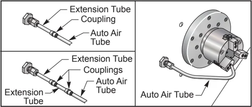
M14 Main Spindle Brake On / M15 Main Spindle Brake Off These M Codes are used for machines equipped with the optional C-Axis. M14 applies a caliper-style brake to hold the main spindle, while M15 releases the brake.
M17 Turret Rotation Always Forward / M18 Turret Rotation Always Reverse M17 and M18 rotate the turret in the forward (M17) or reverse (M18) direction when a tool change is made. M17 and M18 work with other M-codes in the same block. The following M17 program code will cause the tool turret to move forward to tool 1 or reverse to tool 1 if an M18 is commanded.
Forward: N1 T0101 M17; Reverse: N1 T0101 M18;
An M17 or M18 will stay in affect for the remainder of the program. Note that Setting 97, Tool Change Direction, must be set to M17/M18.
M19 Orient Spindle (P and R values are an optional feature) M19 adjusts the spindle to a fixed position. The spindle will only orient to the zero position without the optional M19 spindle orient feature.
The optional Orient Spindle function allows P and R address codes. For example, M19 P270 will orient the spindle to 270 degrees. The R-value allows the programmer to specify up to four decimal places; for example, M19 R123.4567.
Spindle orientation is dependant on the mass, diameter and length of the workpiece and/or the workholding (chuck). Contact the Haas Applications Department if any unusually heavy, large diameter, or long configuration is used.
M21 Tailstock Forward / M22 Tailstock Reverse M21 and M22 position the tailstock. M21 uses Settings 105, 106, and 107 to move to the Tailstock Hold Point. M22 uses Setting 105 to move the tailstock to the Retract Point. Adjust pressure using the valves on the HPU.
M21-M28 Optional User M Function with M-Fin The M codes M21 through M28 are optional for user relays; each M code activating one of the optional relays. The Reset button will terminate any operation that is waiting for a relay-activated accessory to finish (also see M51-58 and M61-68).
Some or all of the M21-25 (M21-M22 on Toolroom and Office lathes) on the I/O PCB may be used for factory-installed options. Inspect the relays for existing wires to determine which have been used. Contact the Haas factory for more details.
M-Code Relays - These outputs can be used to activate probes, auxiliary pumps or clamping devices etc. The auxiliary devices are electrically connected to the terminal strip for the individual relay. The terminal strip has a position for, Normally Open (NO), Normally Closed (NC) and Common (CO).
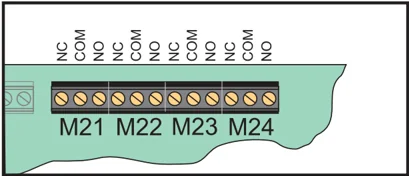
Main I/O PCB M-Code Relays
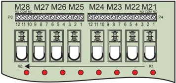
Optional M-Code Relay Board (Mounted above main I/O PCB)
Optional 8M-Code Relays - Additional M-Code relay functions can be purchased in banks of 8. A maximum of two 8M-code relay boards can be installed in the machine, for a total of 16 additional outputs. A total of 4 banks of 8 relays are possible in the Haas system, numbered from 0-3. Banks 0 and 1 are internal to the main I/O PCB. Bank 1 includes the M21-25 relays at the top of the I/O PCB. Bank 2 addresses the first 8M option PCB. Bank 3 addresses the second 8M option PCB.
NOTE: Bank 3 may be used for some Haas installed options and may not be available. Contact the Haas factory for more details.
Only one bank of outputs may be addressable with M-codes at a time. This is controlled by Parameter 352 “Relay Bank Select”. Relays in the non-activated banks are only accessible with macro variables or M59/69. Parameter 352 is shipped set to “1” as standard.
NOTE: With any probing option (wit the exception of LTP), Parameter 352 must be set to ‘1’. When the 8M option is installed, access its relays using M59/69.
M23 Thread Chamfer ON / M24 Thread Chamfer OFF M23 commands the control to execute a chamfer at the end of a thread executed by G76 or G92. M24 commands the control not to perform chamfering at the end of the threading cycles (G76 or G92). An M23 remains in effect until changed by M24, likewise for M24. Refer to Settings 95 and 96 to control the chamfer size and angle. M23 is the default at power-up and when the control is reset.
M30 Program End and Reset M30 stops a program. It stops the spindle and turns off the coolant and the program cursor will return to the start of the program. M30 cancels tool length offsets.
M31 Chip Conveyor Forward / M33 Chip Conveyor Stop M31 starts the optional chip conveyor motor in the forward direction; the direction that moves the chips out of the machine. The conveyor will not turn if the door is open. It is recommended that the chip auger be used intermittently. Continuous operation will cause the motor to overheat.
M33 stops Conveyor motion.
M36 Parts Catcher Up (Optional) / M37 Parts Catcher Down (Optional) M36 activates the optional parts catcher. M37 deactivates the optional parts catcher. M36 rotates the parts catcher into position to catch a part. M37 rotates the parts catcher out of the work envelope.
M38 Spindle Speed Variation On / M39 Spindle Speed Variation Off Spindle Speed Variation (SSV) allows the operator to specify a range within which the spindle speed will continuously vary. This is helpful in suppressing tool chatter, which can lead to undesirable part finish and/ or damage the to cutting tool. The control will vary the spindle speed based on Settings 165 and 166. For example, in order to vary spindle speed +/- 50 RPM from its current commanded speed with a duty cycle of 3 seconds, set Setting 165 to 50 and Setting 166 to 30. Using these settings, the following program will vary the spindle speed between 950 and 1050 RPM after the M38 command.
O0010; S1000 M3 G4 P3. M38 (SSV ON) G4 P60. M39 (SSV OFF) G4 P5. M30
The spindle speed will continuously vary with a duty cycle of 3 seconds until an M39 command is found. At that point the machine will come back to its commanded speed and the SSV mode will be turned off.
A program stop command such as M30 or pressing the Reset button also turns SSV Off. If the RPM swing is larger than the commanded speed value, any negative RPM values (below zero) will translate into an equivalent positive value. The spindle, however, will not be allowed to go below 10 RPM when SSV mode is active.
Constant Surface Speed: When Constant Surface Speed (G96) is activated (which will calculate spindle speed) the M38 command will alter that value using Settings 165 and 166.
Threading Operations: G92, G76 and G32 will allow the spindle speed to vary in SSV mode. This is not recommended due to possible thread lead errors caused by mismatched acceleration of the spindle and the Z-axis.
Tapping cycles: G84, G184, G194, G195 and G196 will be executed at their commanded speed and SSV will not be applied.
M41 Low Gear / M42 High Gear On machines with a transmission, M41 selects low gear and M42 will select high gear.
M43 Turret Unlock / M44 Turret Lock For Service use only.
M51-M58 Set Optional User M Codes The M51 through M58 codes are optional for user interfaces. They will activate one of the relays and leave it active. Use M61-M68 to turn these off. The Reset key will turn off all of these relays. See M121-M128 for details on the M-Code relays.
M59 Set Output Relay This M code turns on a relay. An example of its usage is M59 Pnn, where “nn” is the number of the relay being turned on. An M59 command can be used to turn on any of the discrete output relays in the range from 1100 to 1155. When using Macros, M59 P1103 does the same thing as using the optional macro command #1103 = 1, except that it is processed at the end of the line of code.
NOTE: 8M #1 uses addresses 1140-1147.
M61-M68 Clear Optional User M Codes The M61 through M68 codes are optional for user interfaces. They will turn off one of the relays. Use M51-M58 to turn these on. The Reset key will turn off all of these relays. See M121-M128 for details on the M-Code relays.
M69 Clear Output Relay This M code turns off a relay. An example of its usage is M69 Pnn, where “nn” is the number of the relay being turned off. An M69 command can be used to turn off any of the output relays in the range from 1100 to 1155. When using Macros, M69 P1103 does the same thing as using the optional macro command #1103 = 0, except that it is processed at the end of the line of code.
M76 Disable Display / M77 Enable Display These codes are used to disable and enable the screen display. This M-Code is useful during the running of a large complicated program as refreshing the screen takes processing power that otherwise may be necessary to command the moves of the machine.
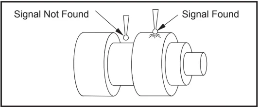
M78 Alarm if Skip Signal Found/M79 Alarm if Skip Signal Not Found This M-code is used with a probe. M78 generates an alarm if a programmed skip function (G31) receives a signal from the probe. This is used when a skip signal is not expected, and may indicate a probe crash. M79 generates an alarm if a programmed skip function (G31) did not receive a signal from the probe. This is used when the lack of the skip signal means a probe positioning error. These codes can be placed on the same line as the skip G-code or in any block after.
 Signal Not Found
Signal Found
M85 Open Automatic Door (Optional) / M86 Close Automatic Door (Optional) M85 opens the Auto Door and M86 closes it. The control pendant beeps when the door is in motion.
M88 High Pressure Coolant On (Optional) / M89 High Pressure Coolant Off (Optional) M88 turns on the high pressure coolant option, an M89 turns the coolant off.
Warning Turn off High Pressure Coolant before performing a tool change.
Use M89 to turn off High Pressure coolant during program execution before rotating the tool turret.
M93 Start Axis Pos Capture / M94 Stop Axis Pos Capture These M codes permit the control to capture the position of an auxiliary axis when a discrete input changes to a 1. The format is M93 Px Qx. P is the axis number. Q is a discrete input number from 0 to 63.
M93 causes the control to watch the discrete input specified by the Q value, and when it goes to a 1, it captures the position of the axis specified by the P value. The position is then copied to hidden macro variables 749. M94 stops the capture. M93 and M94 were introduced to support the Haas Bar Feeder, which uses a single axis controller to the V auxiliary axis. P5 (V axis) and Q2 must be used for the bar feeder.
M95 Sleep Mode Sleep mode is essentially a long dwell (pause). Sleep mode can be used when the user wants the machine to begin warming itself up so it can be ready for use upon the operators arrival. The format of the M95 command is: M95 (hh:mm).
The comment immediately following M95 must contain the hours and minutesfor which the machine is to sleep. For example, if the current time were 6pm and the user wanted the machine to sleep until 6:30am the next day, the following command would be used; M95 (12:30). The line(s) following M95 should be axis moves and spindle warm-up commands.
M96 Jump If No Input P Program block to go to when conditional test is met Q Discrete input variable to test (0 to 63)
This code is used to test a discrete input for 0 (off) status. This is useful for checking the status of automatic work holding or other accessories that will generate a signal for the control. The Q value must be in the range 0 to 63, which corresponds to the inputs found on the diagnostic display (The upper left input is 0 and the lower right is input 63. When this program block is executed and the input signal specified by Q has a value of 0, the program block Pnnnn is performed (the Pnnnn line must be in the same program). M96 Example:
N05 M96 P10 Q8 (Test input #8, Door Switch, until closed); N10 (Start of program loop); . . (Program that machines part); . N85 M21 (Execute an external user function) N90 M96 P10 Q27 (Loop to N10 if spare input [#27] is 0); N95 M30 (If spare input is 1 then end program);
M97 Local Sub-Program Call This code is used to call a subroutine referenced by a line number (N) within the same program. A code is required and must match a line number within the same program. This is useful for simple subroutines within a program; does not require a separate program. The subroutine must end with an M99. An Lnn code in the M97 block will repeat the subroutine call that nn times. M97 Example:
O0001 M97 P1000 L2 (L2 command will cause the program to run the N1000 line twice) M30 N1000 G00 G90 G55 X0 Z0 (N line that will run after M97 P1000 is run) S500 M03 G00 Z-.5 G01 X.5 F100. G03 ZI-.5 G01 X0 Z1. F50. G91 G28 Z0 G90 M99
M98 Sub Program Call
This code is used to call a subroutine, the format is M98 Pnnnn (Pnnnn is the number of the program being called). The subprogram must be in the program list, and it must contain M99 to return to the main program. An Lnn count can be put on the line containing M98 and will cause the subroutine to be called nn times before continuing to the next block.
O0001 (Main Program number) M98 P100 L4; (Call sub-program, sub -program number, loop 4 times) M30 (End of program)
O0100 (Sub-program Number) G00 G90 G55 X0 Z0 (N line that will run after M97 P1000 is run) S500 M03 G00 Z-.5 G01 X.5 F100. G03 ZI-.5 G01 X0 Z1. F50. G91 G28 Z0 G90 M99
M99 Sub-Program Return or Loop
This code is used to return to the main program from a subroutine or macro, the format is M99 Pnnnn (Pnnnn is the line in the main program to return to). It will cause the main program to loop back to the beginning without stopping when used in the main program.
Programming Notes - You can simulate Fanuc behavior by using the following code:
calling program: Haas Fanuc O0001 O0001 ... ... N50 M98 P2 N50 M98 P2 N51 M99 P100 ... ... N100 (continue here) N100 (continue here) ... ... M30 M30
subroutine: O0002 O0002 M99 M99 P100
M99 With Macros
If the machine is equipped with the optional macros, you can use a global variable and specify a block to jump to by adding #nnn = dddd in the subroutine and then using M99 P#nnn after the subroutine call.
M104 Extend Probe Arm / M105 Retract Probe Arm
The optional tool setting probe arm is extended and retracted using M104 and M105.
M109 Interactive User Input
This M code allows a G-code program to place a short prompt (message) on the screen. A macro variable in the range 500 through 599 must be specified by a P code. The program can check for any character that can be entered from the keyboard by comparing with the decimal equivalent of the ASCII character (G47, Text Engraving, has a list of ASCII characters).
The following sample program will ask the user a Yes or No question, then wait for either a “Y” or an “N” to be entered. All other characters will be ignored.
170 M Codes 96-8700 rev U June 2008
N1 #501= 0. (Clear the variable) M109 P501 (Sleep 1 min?) N5 IF [ #501 EQ 0. ] GOTO5 (Wait for a key) IF [ #501 EQ 89. ] GOTO10 (Y) IF [ #501 EQ 78. ] GOTO20 (N) GOTO1 (Keep checking) N10 (A Y was entered) M95 (00:01) GOTO30 N20 (An N was entered) G04 P1.(Do nothing for 1 second) N30 (Stop) M30
The following sample program will ask the user to select a number, then wait for a 1, 2, 3, 4 or a 5 to be entered; all other characters will be ignored. % O01234 (M109 Program)
N1 #501= 0 (Clear Variable #501) (Variable #501 will be checked) (Operator enters one of the following selections) M109 P501 (1,2,3,4,5) N5 IF [ #501 EQ 0 ] GOTO5 (Wait for keyboard entry loop until entry)
(Decimal equivalent from 49-53 represent 1-5) IF [ #501 EQ 49 ] GOTO10 (1 was entered go to N10) IF [ #501 EQ 50 ] GOTO20 (2 was entered go to N20) IF [ #501 EQ 51 ] GOTO30 (3 was entered go to N30) IF [ #501 EQ 52 ] GOTO40 (4 was entered go to N40) IF [ #501 EQ 53 ] GOTO50 (5 was entered go to N50)
GOTO1 (Keep checking for user input loop until found)
N10 (If 1 was entered run this sub-routine) (Go to sleep for 10 minutes) #3006= 25 (Cycle start sleeps for 10 minutes) M95 (00:10) GOTO100
N20 (If 2 was entered run this sub routine) (Programmed message) #3006= 25 (Programmed message cycle start) GOTO100
N30 (If 3 was entered run this sub routine) (Run sub program 20) #3006= 25 (Cycle start program 20 will run) G65 P20 (Call sub-program 20) GOTO100
96-8700 rev U June 2008 M Codes 171
N40 (If 4 was entered run this sub routine) (Run sub program 22) #3006= 25 (Cycle start program 22 will be run) M98 P22 (Call sub program 22) GOTO100
N50 (If 5 was entered run this sub-routine) (Programmed message) #3006= 25 (Reset or cycle start will turn power off) #1106= 1
N100 M30 %
M119 Subspindle Orient
This command will cause the subspindle to be oriented to the position specified by the P or R command. The format is: M119 Pxxx/M119 Rxx.x.
M121-M128 Optional User M
The M121 through M128 codes are optional for user interfaces. They will activate one of relays 1132 through 1139, wait for the M-fin signal, release the relay, and wait for the M-fin signal to cease. The Reset button will terminate any operation that is hung-up waiting for M-fin.
M133/M134/M135 Live Tool Drive Commands
M133 turns the live tool spindle in the forward direction. M134 turns the live tool spindle in the reverse direction. M135 stops the live tool spindle.
Spindle speed is controlled with a P address code. For example, P1200 would command a spindle speed of 1200 RPM.
M143/M144/M145 Sub Spindle Commands (Optional)
M143 turns the sub spindle in the forward direction. M144 turns the sub spindle in the reverse direction. M145 stops the sub spindle
The sub spindle speed is controlled with an P address code, for example, P1200 will command a spindle speed of 1200 RPM.
M154 C-Axis Engage / M155 C-Axis Disengage (Optional)
This M code is used to engage or disengage the optional C-axis motor.