SETTINGS
The setting pages contain values that control machine operation and that the user may need to change. Most settings can be changed by the operator. They are preceded by a short description on the left and the value on the right. In general, settings allow the operator or setup person to lock out or turn on specific functions.
The settings are organized into pages of functionally similar groupings. This will make it easier for the user to remember where the settings are located and reduces the amount of time spent maneuvering through the settings display. The list below is separated into page groups with the page title as the heading.
Use the vertical cursor keys to move to the desired setting. Depending on the setting, you may change it by entering a new number or, if the setting has specific values, press the horizontal cursor keys to display the choices. Press the Write key to enter or change the value. The message near the top of the screen tells you how to change the selected setting.
The serial number is Setting 26 on this page and is protected from user change. If you need to change this setting, contact Haas or your dealer. The following is a detailed description of each of the settings:
1 - Auto Power Off Timer
This setting is used to power-down the machine when it has not been used for some time. The value entered in this setting is the number of minutes the machine will remain idle until it is powered down. The machine will not be powered down while a program is running, and the time (number of minutes) will start back at zero anytime buttons is pressed or the jog handle is used. The auto-off sequence gives the operator a 15-second warning before power down, at which time pressing any button will stop the power down.
2 - Power Off at M30
Powers down the machine at the end of a program (M30) if this setting is set to "On". The machine will give the operator a 30-second warning once an M30 is reached; pressing any button will interrupt the sequence.
4 - Graphics Rapid Path
This setting changes the way a program is viewed in the Graphics mode. When it is Off, rapid (non-cutting tool motions do not leave a path. When it is On, rapid tool motions leave a dashed line on the screen.

5 - Graphics Drill Point
This setting changes the way a program is viewed in Graphics mode. When it is ON, motion in the Z-axis will leave an X mark on the screen. When it is OFF, no additional marks are shown on the graphics display.
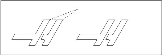
6 - Front Panel Lock
This Setting disables the Spindle CW and CCW buttons when it is set to "On".

7 - Parameter Lock
Turning this setting On will stop the parameters from being changed, except for parameters 81-100. Note that when the control is powered up, this setting is on.
8 - Prog Memory Lock
This setting locks out the memory editing functions (Alter, Insert, etc.) when it is set to On.
9 - Dimensioning
This setting selects between inch and metric mode. When it is set to Inch, the programmed units for X, Y, and Z are inches, to 0.0001". When it is set to Metric, programmed units are millimeters, to 0.001mm. All offset values are converted when this setting is changed from inches to metric, or vice versa. However, changing this setting will not automatically translate a program stored in memory; you must change the programmed axis values for the new units.
When set to Inch, the default G code is G20, when set to Metric, the default G code is G21.
| INCH | METRIC | |
|---|---|---|
| Feed | inches/min. | mm/min. |
| Max Travel | +/- 15400.0000 | +/-39300.000 |
| Min. Programmable Dimension | .0001 | .001 |
| Feed Range | .0001 to 300.000 in/min. | .001 to 1000.000 |
| Axis Jog Keys | ||
|---|---|---|
| .0001 Key | .0001 in/jog click | .001 mm/jog click |
| .001 | .001 in/jog click | .01 mm/jog click |
| .01 | .01 in/jog click | .1 mm/jog click |
| .1 Key | .1 in/jog click | 1 mm/jog click |
10 - Limit Rapid at 50%
Turning this setting On will limit the machine to 50% of its fastest non-cutting axis motion (rapids). This means, if the machine can position the axes at 700 inches per minute (ipm), it will be limited to 350 ipm when this setting is On. The control will display a 50% rapid override message, when this setting is on. When it is Off, the highest rapid speed of 100% is available.
11 - Baud Rate Select
This setting allows the operator to change the rate at which data is transferred to/from the first serial port (RS-232). This applies to the upload/download of programs, etc., and to DNC functions. This setting must match the transfer rate from the personal computer.
12 - Parity Select
This setting defines parity for the first serial port (RS-232). When set to None, no parity bit is added to the serial data. When set to Zero, a 0 bit is added. Even and Odd work like normal parity functions. Make sure you know what your system needs, for example, XMODEM must use 8 data bits and no parity (set to “None”). This setting must match the transfer rate from the personal computer.
13 - Stop Bit
This setting designates the number of stop bits for the first serial port (RS-232). It can be 1 or 2. This setting must match the transfer rate from the personal computer.
14 - Synchronization
This changes the synchronization protocol between sender and receiver for the first serial port (RS-232). This setting must match the transfer rate from the personal computer.
When set to RTS/CTS, the signal wires in the serial data cable are used to tell the sender to temporarily stop sending data while the receiver catches up.
When set to XON/XOFF, the most common setting, ASCII character codes are used by the receiver to tell the sender to temporarily stop.
The selection DC Codes is like XON/XOFF, except that paper tape punch or reader start/stop codes are sent.
XMODEM is a receiver-driven communications protocol that sends data in blocks of 128 bytes. XMODEM has added reliability as each block is checked for integrity. XMODEM must use 8 data bits and no parity.
Settings 16-21 These settings can be turned on in order to stop unfamiliar operators from altering the machine’s functions and causing damage to the machine or workpiece.
16 - Dry Run Lock Out The Dry Run feature will not be available when this setting is turned On.
17 - Opt Stop Lock Out The Optional Stop feature will not be available when this setting is On.
18 - Block Delete Lock Out The Block Delete feature will not be available when this setting is On.
19 - Feedrate Override Lock The feedrate override buttons will be disabled when this setting is turned On.
20 - Spindle Override Lock The spindle speed override buttons will be disabled when this setting is turned On.
21 - Rapid Override Lock The axis rapid override buttons are disabled when this setting is turned On.
22 - Can Cycle Delta Z This setting specifies the distance the Z-axis is retracted to clear chips during a G73 canned cycle. The range is 0.0 to 29.9999 inches (0-760 mm).
23 - 9xxx Progs Edit Lock Turning this setting on will stop the 9000 series of programs from being viewed, edited or deleted. 9000 series programs cannot be uploaded or downloaded with this setting on. Note that 9000 series programs are usually macro programs.
24 - Leader To Punch This setting is used to control the leader (the blank tape at the beginning of a program) sent to a paper tape punch device connected to the first RS-232 port.
25 - EOB Pattern This setting controls the EOB (End of Block) pattern when data is sent and received to/from serial port 1 (RS-232). This setting must match the transfer rate from the personal computer.
26 - Serial Number This is the serial number of your machine. It cannot be changed.
28 - Can Cycle Act w/o X/Z Turning this setting On will cause the commanded canned cycle to complete without an X or Z command. The preferred method of operation is with this setting On.
When this setting is Off, the control will stop if a canned cycle is programmed without an X or Z axis move.
96-8700 rev U June 2008 Settings 175
31 - Reset Program Pointer When this setting is Off, the Reset button will not change the position of the program pointer. When it is On, the Reset button will move the program pointer to the beginning of the program.
32 - Coolant Override This setting controls how the coolant pump operates. The "Normal" selection allows the operator to turn the pump on and off manually or with M-codes. The "Off" selection will generate an alarm if an attempt is made to turn the coolant on manually or from a program. The "Ignore" selection will ignore all programmed coolant commands, but the pump can be turned on manually.
33 - Coordinate System This setting changes the way tool shift offsets work. It can be set to either Yasnac or Fanuc. This setting changes the way a Txxxx command is interpreted and the way the coordinate system is specified. If it is Yasnac, tool shifts 51 to 100 are available on the offsets display and G50 T5100 is allowed. If it is FANUC, tool geometry for tools 1 to 50 is available on the offsets display and G54 style work coordinates are available.
36 - Program Restart When this setting is On, restarting a program from a point other than the beginning will direct the control to scan the entire program to ensure that the tools, offsets, G and M codes, and axis positions are set correctly before the program starts at the block where the cursor is positioned. The following M codes will be processed when Setting 36 is enabled: M08 Coolant On M09 Coolant Off M14 Clmp Main Spndl M15 Unclmp Main Spndl M36 Parts Catcher On M37 Parts Catcher Off M41 Low Gear M42 High Gear M51-58 Set User M M61-68 Clear User M
When it is Off the program will start without checking the conditions of the machine. Having this setting Off may save time when running a proven program.
37 - RS-232 Data Bits This setting is used to change the number of data bits for serial port 1 (RS-232). This setting must match the transfer rate from the personal computer. Normally 7 data bits should be used but some computers require 8. XMODEM must use 8 data bits and no parity.
38 - Aux Axis Number This is a numeric entry between 0 and 1. It is used to select the number of external auxiliary axes added to the system. If it is set to 0, there are no auxiliary axes. If it is set to 1, there is a V-axis.
39 - Beep @ M00, M01, M02, M30 Turning this setting On will cause the keyboard beeper to sound when an M00, M01 (with Optional Stop active), M02 or an M30 is found. The beeper will continue until a button is pressed.
41 - Add Spaces RS-232 Out When this setting is On, spaces are added between address codes when a program is sent out via RS-232 serial port 1. This can make a program much easier to read/edit on a personal computer (PC). When it is set to Off, programs sent out the serial port have no spaces and are more difficult to read.
42 - M00 After Tool Change Turning this setting On will stop the program after a tool change and a message will be displayed stating this. The Cycle Start button must be pressed to continue the program.
43 - Cutter Comp Type This setting controls how the first stroke of a compensated cut begins and the way the tool is cleared from the part being cut. The selections can be A or B; see the cutter compensation section for examples.
176 Settings 96-8700 rev U June 2008
44 - Min F in Radius TNC % (Minimum feedrate in radius tool nose compensation percent) This setting affects the feed rate when cutter compensation moves the tool towards the inside of a circular cut. This type of cut will slow down to maintain a constant surface feed rate. This setting specifies the slowest feed rate as a percentage of the programmed feed rate (range 1-100).
45 - Mirror Image X-axis 47 - Mirror Image Z-xis When one or more of these settings is On, axis motion will be mirrored (reversed) around the work zero point. See also G101, Enable Mirror Image, in G-codes section.
50 - Aux Axis Sync This changes the synchronization between sender and receiver for the second serial port. The second serial port is used for auxiliary axes. The settings between the CNC control and the auxiliary axes must be the same.
Selecting “RTS/CTS” will tell the sender to temporarily stop sending data while the receiver catches up.
Selecting “XON/XOFF” uses ASCII character codes from the receiver to tell the sender to temporarily stop. XON/XOFF is the most common setting.
The “DC Codes” selection is like XON/XOFF, with the exception that start/stop codes are sent.
The “XMODEM” selection is receiver-driven, which sends data in blocks of 128 bytes. XMODEM gives the RS-232 communication added reliability because each block is checked for integrity.
51 - Door Hold Switch Override (Safety Switch Override) Selecting “Off” will not allow a program to start when the doors are open, and opening a door will cause the running program to stop (the same as pressing Feed Hold).
Machines equipped with a hand held safety switch will go into feed hold if the safety switch is released.
When the control is powered on, this setting automatically returns to Off.
52 - G83 Retract Above R Range 0.0 to 30.00 inches or 0-761mm). This setting changes the way G83 (peck drilling cycle) behave. Most programmers set the reference (R) plane well above the cut to ensure that the chip clearing motion actually allows the chips to get out of the hole. However this wastes time as the machine will “drill” through this empty distance. If Setting 52 is set to the distance required to clear chips, the R plane can be put much closer to the part being drilled.
 Setting 52
Start Position
R Plane
New R Plane
Face of Part
53 - Jog w/o Zero Return Turning this setting On allows the axes to be jogged without zero returning the machine (finding machine home). This is a dangerous condition as the axis can be run into the mechanical stops and the possibly damage the machine. When the control is powered up, this setting automatically returns to Off.
54 - Aux Axis Baud Rate This setting allows the operator to change the data rate for the second serial port (Auxiliary axis). This setting needs to match the value in the auxiliary axis control.
55 - Enable DNC from MDI Turning this setting "On" will make the DNC feature available. DNC is selected, in the control by pressing the MDI/DNC button twice.
The DNC Direct Numeric Control feature is not available when set to "Off".
56 - M30 Restore Default G When this setting is On, ending a program with M30 or pressing Reset returns all modal G codes to their defaults.
57 - Exact Stop Canned X-Z The rapid XZ motion associated with a canned cycle may not achieve an exact stop when this setting is Off. Turning this setting On will ensure that the XZ motion comes to an exact stop.
58 - Cutter Compensation This setting selects the type of cutter compensation used (FANUC or YASNAC). See the cutter compensation section.
59 - Probe Offset X+ 60 - Probe Offset X- 61 - Probe Offset Z+ 62 - Probe Offset Z- These settings are used to define the displacement and size of the spindle probe. These four settings specify the travel distance and direction from where the probe is triggered to where the actual sensed surface is located. These settings are used by G31, G36, G136, and M75 codes. The values entered for each setting can be either positive or negative numbers.
Macros can be used to access these settings, see the Macro section for more information.
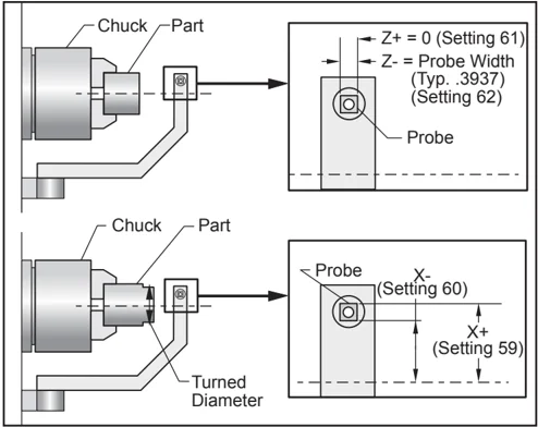
63 - Tool Probe Width This setting is used to specify the width of the probe used to test tool diameter. This setting only applies to the probing option; it is used by G35.
64 - T. OFS Meas Uses Work This setting changes the way the Tool Oset Mesur (Tool Offset Measure) button works. When this is On, the entered tool offset will be the measured tool offset plus the work coordinate offset (Z-axis). When it is Off, the tool offset equals the Z machine position.
65 - Graph Scale (Height) This setting specifies the height of the work area that is displayed on the Graphics mode screen. The default value for this setting is the maximum height, which is the entire machine work area. Using the following formula can set a specific scale: Total Y travel = Parameter 20/Parameter 19 Scale = Total Y travel/Setting 65
66 - Graphics X Offset This setting locates the right side of the scaling window relative to the machine X zero position (see the Graphics section). Its default is zero.
68 - Graphics Z Offset This setting locates the top of the zoom window relative to the machine Z zero position (see the Graphics section). Its default is zero.
 Graphics Mode
Setting 66 & 68 set to Ø
Setting 66 & 68 set to 2.0
69 - DPRNT Leading Spaces This is an On/Off setting. When set to Off, the control will not use leading spaces generated by a macro DPRNT format statement. Conversely, when set to On, the control will use leading spaces The following example illustrates control behavior when this setting is OFF or ON.
#1 = 3.0 ; G0 G90 X#1 ; DPRNT[X#1[44]] ;
OUTPUT OFF X3.0000
ON X 3.0000
Notice the space between the "X" and the 3 when the setting is On. Information can be easier to read when this setting is On.
70 - DPRNT Open/CLOS DCode This setting controls whether the POPEN and PCLOS statements in macros send DC control codes to the serial port. When the setting is On, these statements will send DC control codes. When it is Off, the control codes are suppressed. Its default value is On.
72 - Can Cycle Cut Depth Used with canned cycles G71 and G72, this setting specifies the incremental depth for each pass during rough cutting. It is used if the programmer does not specify a D code. Valid values range from 0 to 29.9999 inches or 299.999 mm. The default value is .1000 inches.
73 - Can Cycle Retraction Used with canned cycles G71 and G72, this setting specifies the retraction amount after a roughing cut. It represents the tool to material clearance as the tool returns for another pass. Valid values range from 0 to 29.9999 inches or 299.999 mm. The default value is .0500 inches.
74 - 9xxx Progs Trace
This setting, along with Setting 75, is useful for debugging CNC programs. When Setting 74 is On, the control will display the code in the macro programs (O9xxxx). When the setting is Off, the control will not display the 9000 series code.
75 - 9xxxx Progs Singls BLK
When Setting 75 is On and the control is operating in Single Block mode, then the control will stop at each block of code in a macro program (O9xxxx) and wait for the operator to press Cycle Start. When Setting 75 is Off, the macro program is run continuously, the control will not pause at each block, even if Single Block is on. The default setting is On.
When Setting 74 and Setting 75 are both On, the control acts normally. That is, all blocks executed are highlighted and displayed, and when in Single Block mode there is a pause before each block is executed.
When Setting 74 and Setting 75 are both Off, the control will execute 9000 series programs without displaying the program code. If the control is in Single Block mode, no single-block pause will occur during the running of the 9000 series program.
When Setting 75 is On and Setting 74 is Off, then 9000 series programs are displayed as they are executed.
76 - Foot Pedal Lock Out
This is an On/Off setting. When it is Off, the foot pedal operates normally. When it is On, any action at the foot pedal is ignored by the control.
77 - Scale Integer F
This setting allows the operator to select how the control interprets an F value (feedrate) that does not contain a decimal point. (It is recommended that programmers always use a decimal point.) This setting helps operators run programs developed on a control other than Haas. For Example F12:
- Setting 77 Off 0.0012 units/minute
- Setting 77 On 12.0 units/minute
There are 5 feedrate settings:
| INCH | MILLIMETER | ||
|---|---|---|---|
| DEFAULT | (.0001) | DEFAULT | (.001) |
| INTEGER | F1 = F1 | INTEGER | F1 = F1 |
| .1 | F1 = F.0001 | .1 | F1 = F.001 |
| .01 | F10 = F.001 | .01 | F10 = F.01 |
| .001 | F100 = F.01 | .001 | F100 = F.1 |
| .0001 | F1000 = F.1 | .0001 | F1000 = F1 |
81 - Tool at Auto Off
When the Power Up/Restart key is pressed, the control will change to the tool specified in this setting. If zero (0) is specified, no tool change occurs at power up. The default setting is 1.
82 - Language
Languages other than English are available in the Haas control. To change to another language, choose a language and press Enter.
83 - M30/Resets Overrides
When this setting is On, an M30 restores any overrides (feedrate, spindle, rapid) to their default values (100%).
84 - Tool Overload Action
This setting causes the specified action (Alarm, Feedhold, Beep, Autofeed) to occur anytime a tool becomes overloaded (see the Tooling section).
Choosing “Alarm” will cause the machine to stop when the tool is overloaded.
When set to “Feedhold”, the message “Tool Overload” will be displayed and the machine will stop in a feed-hold situation when this condition occurs. Pressing any key will clear the message.
Selecting “Beep” will cause an audible noise (beep) from the control when the tool is overloaded.
When set to “Autofeed”, the lathe automatically limits the feedrate based on the tool load.
Autofeed Notes: When tapping (rigid or floating), the feed and spindle overrides will be locked out, so the Autofeed feature will be ineffective (the control will appear to respond to the override buttons, by displaying the override messages). The Autofeed feature should not be used when thread milling or auto reversing tap-ping heads, as it may cause unpredictable results or even a crash.
The last commanded feedrate would be restored at the end of the program execution, or when the operator presses Reset or turns off the Autofeed feature. The operator may use the keyboard feedrate override buttons while the Autofeed feature is selected. These buttons will be recognized by the Autofeed feature as the new commanded feedrate as long as the tool load limit is not exceeded. However, if the tool load limit has already been exceeded, the control will ignore the feedrate override buttons.
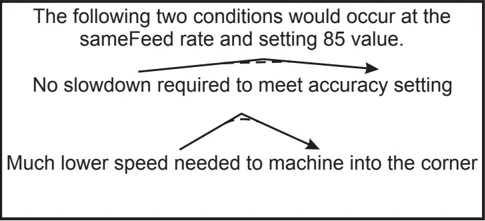
85 - Maximum Corner Rounding
Defines the machining accuracy of rounded corners within a selected tolerance. The initial default value is 0.05 inch. If this setting is zero (0), the control acts as if an exact stop is commanded in each motion block.
 Program Point
Setting 85= 0.002
Setting 85= 0.005
The following two conditions would occur at the sameFeed rate and setting 85 value.
No slowdown required to meet accuracy setting
Much lower speed needed to machine into the corner
86 - Thread Finish Allowance
Used in G76 canned threading cycle, this setting specifies how much material will be left on the thread for finishing after all passes of the cycle. Values range from 0 to .9999 inches. The default value is 0.
87 - TNN Resets Override
This is an on/off setting. When M06 is executed and this setting is on, any overrides are canceled and set to their programmed values.
88 - Reset Resets Overrides
This is an On/Off setting. When it is On and the Reset key is pressed, any overrides are canceled and set to their programmed values or defaults.
90 - Graph Z Zero Location
This setting adjusts for extreme values in tool geometry or shift values. In graphics, tool offsets are ignored so that the cutting paths of different tools are displayed in the same location. Setting this to an approximate value of machine coordinates for the programmed part zero will void any Z Over Travel Range alarms that you may encounter in graphics. The default is -8.0000.
91 - Graph X Zero Location
This setting adjusts for extreme values in tool geometry or shift values. In graphics, tool offsets are ignored so that the cutting paths of different tools are displayed in the same location. Setting this to an approximate value of machine coordinates for the programmed part zero will void any x Over Travel Range alarms that you may encounter in graphics. The default is -8.0000.
92 - Chuck Clamping This setting determines chuck clamping direction. Set to O.D., the chuck is considered clamped when the jaws are moved to the spindle center. Set to I.D., the chuck is considered clamped when the jaws are moved away from the spindle center.
93 - Tailstock X Clearance This setting works with Setting 94 to define a tail stock travel restriction zone that limits interaction between the tail stock and the tool turret. This setting determines the X-axis travel limit when the difference between the Z-axis location and the tail stock location falls below the value in Setting 94. If this condition occurs and a program is running then an alarm is generated. When jogging, no alarm is generated, but travel will be limited. Units are in inches.
94 - Tailstock Z Clearance This setting is the minimum allowable difference between the Z-axis and the tail stock (see Setting 93). Units are in inches. A value of -1.0000 means that when the X-axis is below the X clearance plane (Setting 93), the Z-axis must be more than 1 inch away from the tail stock position in the Z-axis negative direction. The default value for this setting is zero. Units are in inches.
95 - Thread Chamfer Size This setting is used in G76 and G92 threading cycles when an M23 is commanded. When command M23 is active, threading strokes end with an angled retraction, as opposed to pulling straight out. The value in Setting 95 is equal to the number of turns (chamfered threads) desired. Note that Settings 95 and 96 interact with each other. Valid range: 0 to 29.999 (Multiple of current thread lead, F or E).
 G76 or G92 Threading Stroke with M23 active
Thread
Tool Path
- Programmed Thread Endpoint \Delta Setting 95 x L \alpha Setting 96 = 45 L Lead • Actual Stroke Endpoint
96 - Thread Chamfer Angle See Setting 95. Valid range: 0 to 89 degrees (No decimal point allowed)
97 - Tool Change Direction This setting determines the default tool change direction. It may be set to either Shortest or M17/M18.
When "Shortest" is selected, the control will turn the direction necessary to reach the next tool with the least movement. The program can still use M17 and M18 to fix the tool change direction, but once this is done it is not possible to revert back to the shortest tool direction other than Reset or M30/M02.
Selecting M17/M18, the control will move the tool turret either always forward or always reverse based on the most recent M17 or M18. When Reset, power on, or M30/M02 is executed, the control will assume M17 as the tool turret direction during tool changes, always forward. This option is useful when a program must avoid certain areas of the tool turret due to odd-sized tools.
98 - Spindle Jog RPM This setting determines the spindle rpm for the Spindle Jog key. The default value is 100 RPM.
99 - Thread Minimum Cut Used in G76 canned threading cycle, this setting sets a minimum amount of successive passes of the thread cut. Succeeding passes cannot be less than the value in this setting. Values can range from 0 through .9999 inch. The default value is .0010 inches.
100 - Screen Saver Delay When the setting is zero, the scren saver is disabled. If setting is set to some number of minutes, then after that time with no keyboard activity the IPS screen will be displayed. After the second screen saver delay, the Haas logo will be displayed that will change position every 2 seconds (deactivate with any key press, handle jog or alarm). The screen saver will not activate if the control is in Sleep, Jog, Edit, or Graphics mode.
101 - Feed Override -> Rapid Turning this setting On and pressing Handle Control Feedrate will cause the jog handle to affect both the feedrate and the rapid rate overrides. Setting 10 affects the maximum rapid rate.
102 - C Axis Diameter This setting supports the C-axis. See the C-axis Section. The default value is 1.0 inches and the maximum allowable value is 29.999 inches.
103 - CYC START/FH Same Key The Cycle Start button must be pressed and held to run a program when this setting is On. When Cycle Start is released, a feed hold is generated. This setting cannot be turned on while Setting 104 is on. When one of them is set to On, the other will automatically turn off.
104 - Jog Handle to SNGL BLK The jog handle can be used to single-step through a program when this setting is On. Reversing the jog handle direction will generate a feed hold. This setting cannot be turned On while Setting 103 is on. When one of them is set to On, the other will automatically turn off.
105 - TS Retract Distance The distance from the Hold Point (Setting 107) the tail stock will retract when commanded. This setting should be a positive value.
106 - TS Advance Distance When the tail stock is moving toward the Hold Point (Setting 107), this is the point where it will stop its rapid movement and begin a feed. This setting should be a positive value.
107 - TS Hold Point This setting is in absolute machine coordinates and should be a negative value. It is the point to advance to for holding when M21 is commanded. Usually this is inside of a part being held. It is determined by jogging to the part and adding some amount to the absolute position.
109 - Warm-Up Time in MIN. This is the number of minutes (up to 300 minutes from power-up) during which the compensations specified in Settings 110-112 are applied.
Overview – When the machine is powered on, if Setting 109, and at least one of Settings 110, 111, or 112, are set to a nonzero value, the following warning will be displayed: CAUTION! Warm up Compensation is specified! Do you wish to activate Warm up Compensation (Y/N)? If a 'Y' is entered, the control immediately applies the total compensation (Setting 110,111, 112), and the compensation begins to decrease as the time elapses. For instance, after 50% of the time in Setting 109 has elapsed, the compensation distance will be 50%. To "restart" the time period, it is necessary to power the machine off and on, and then answer "yes" to the compensation query at start-up.
96-8700 rev U June 2008 Settings 183
CAUTION! Changing Setting 110, 111, or 112 while compensation is in progress can cause a sudden movement of up to 0.0044 inch.
The amount of remaining warmup time is displayed on the bottom right hand corner of the Diagnostics Inputs 2 screen using the standard hh:mm:ss format.
110 - Warmup X Distance 112 - Warmup Z Distance Settings 110 and 112 specify the amount of compensation (max = ± 0.0020" or ± 0.051 mm) applied to the axes. Setting 109 must have a value entered for settings 110 and 112 to have an affect.
113 - Tool Change Method This setting is used for the TL-1 and TL-2 lathes. See the Toolroom Lathe manual.
114 - Conveyor Cycle (minutes) 115 - Conveyor On-time (minutes) These two settings control the optional chip conveyor. Setting 114 (Conveyor Cycle Time) is the interval that the conveyor will turn on automatically. Setting 115 (Conveyor On-Time) is the amount of time the conveyor will run. For example, if setting 114 is set to 30 and setting 115 is set to 2, the chip conveyor will turn on every half an hour, run for 2 minutes, then turn off.
On-time should be set no greater than 80% of cycle time. Note the following:
- The CHIP FWD button (or M31) will start the conveyor in the forward direction and activate the cycle.
- The CHIP REV button (or M32) will start the conveyor in the reverse direction and activate the cycle
- The CHIP STOP button (or M33) will stop the conveyor and cancel the cycle.
118 - M99 Bumps M30 CNTRS When this setting is On, an M99 will add one to the M30 counters (these are visible on the Curnt Comnds displays). Note that an M99 will only increase the counters as it occurs in a main program, not a sub-program.
119 - Offset Lock Turning the setting On will not allow the values in the Offset display to be altered. However, programs that alter offsets will still be able to do so.
120 - Macro Var Lock Turning this setting On will not allow the macro variables to be altered. However, programs that alter macro variables will still be able to do so.
121 - Foot Pedal TS Alarm When M21 is used to move the tail stock to the hold point and hold a part, the control will generate an alarm if a part is not found and the hold point is reached. Setting 121 can be switched to On and an alarm will be generated when the foot pedal is used to move the tail stock to the hold point and no part is found.
122 - SS Chuck Clamping This feature supports Subspindle lathes. Its value can be either O.D. or I.D; similar to Setting 92 for the main spindle.
131 - Auto Door This setting supports the Auto Door option. It should be set to On for machines with an autodoor. Also see M85/86 (Autodoor Open/Close M-codes).
The door will close when Cycle Start is pressed and will open when the program reaches an M00, M01 (with Optional Stop turned on) or M30 and the spindle has stopped turning.
132 - Jog or Home Before TC When this setting is Off, the machine behaves normally. When it is On and Turret Fwd, Turret Rev, or Next Tool is pressed while one or more axes is away from zero, it is assumed that a crash is likely and a message is displayed instead of doing the tool change. However, if the operator had pressed Handle Jog prior to the tool change, it is assumed that the axis had just been jogged to a safe position and will perform the tool change.
133 - REPT Rigid Tap This setting ensures that the spindle is oriented during tapping so that the threads will line up when a second tapping pass, in the same hole, is programmed.
142 - Offset Chng Tolerance This setting generates a warning message if an offset is changed by more than the amount entered for this setting. The following prompt will be displayed: "XX changes the offset by more than Setting 142! Accept (Y/N)?" if an attempt is made to change an offset by more than the entered amount (either positive or negative). If "Y" is entered, the control updates the offset as usual; otherwise, the change is rejected.
If "Y" is entered, the control updates the offset as usual, otherwise, the change is rejected.
143 Machine Data Collect This setting enables the user to extract data from the control using a Q command sent through the RS-232 port, and to set Macro variables by using an E command. This feature is software-based and requires an additional computer to request, interpret and store data from the control. A hardware option also allows the reading of machine status. See CNC Data Transfer in the Operation Programming section for detailed information.
144 - Feed Overide->Spindle This setting is intended to keep the chip load constant when an override is applied. When this setting is On, any feedrate override will also be applied to the spindle speed, and the spindle overrides will be disabled.
145 - TS at Part for CS (Tail stock at part for Cycle Start) When it is Off, the machine behaves as before. When this setting is On, the tail stock must be pressing against the part at the moment Cycle Start is pressed or a message is displayed and the program will not start.
156 - Save Offset with PROG Turning this setting On will have the control save the offsets in the same file as the programs, but under the heading O999999. The offsets will appear in the file before the final % sign.
157 - Offset Format Type This setting controls the format in which offsets are saved with programs.
When it is set to A the format looks like what is displayed on the control, and contains decimal points and column headings. Offsets saved in this format can be more easily edited on a PC and later reloaded.
When it is set to B, each offset is saved on a separate line with an N value and a V value.
158,159,160 - XYZ Screw Thermal COMP% These settings can be set from -30 to +30 and will adjust the existing screw thermal compensation by -30% to +30% accordingly.
162 - Default To Float
When this setting is On, the control will add a decimal point to values entered without a decimal point (for certain address codes.) When the setting is Off, values following address codes that do not include decimal points are taken as machinists notation (i.e., thousandths or ten-thousandths.) This setting will exclude the A value (tool angle) in a G76 block. Thus, the feature applies to the following address codes:
| Value entered | With Setting Off | With Setting On | |
|---|---|---|---|
| In Inch mode | X-2 | X-.0002 | X-2. |
| In MM mode | X-2 | X-.002 | X-2. |
This feature applies to the following address codes: X, Y, Z, A, B, C, E, F, I, J, K, U, W A (except with G76)If a G76 A value containing a decimal point is found during program execution, alarm 605 Invalid Tool Nose Angle is generated. D (except with G73) R (except with G71 in YASNAC mode)
Note that this setting affects the interpretation of all programs entered either manually or from disk or via RS-232. It does not alter the effect of setting 77 Scale Integer F.
163 - Disable .1 Jog Rate
This setting disables the highest jog rate. If the highest jog rate is selected, the next lower rate is automatically selected instead.
164 - Powerup SP Max RPM
This setting is used to set the maximum spindle RPM each time the machine is powered on. It will essentially cause a G50 Snnn command to be executed at power on time, where nnn is the value from the setting. If the setting contains zero, or a value equal to or greater than parameter 131 MAX SPINDLE RPM, Setting 164 will have no effect.
165 - SSV Variation
Specifies the amount by which to allow the RPM to vary above and below its commanded value during the use of the Spindle Speed Variation feature. Positive value only.
166 - SSV CYCLE (0.1) SECS
Specifies the duty cycle, or the rate of change of Spindle Speed. Positive value only.
167-186 - Periodic Maintenance
There are 14 items that can be monitored, as well as six spare items, in the periodic maintenance settings. These settings will allow the user to change the default number of hours for each item when it is initialized during use. If the number of hours is set to zero, the item will not appear in the list of items shown in the maintenance page of current commands.
187 - Machine Data Echo
Turning this setting on will display the data collection Q commands on the PC screen.
201 - Show Only Work and Tool Offsets In Use
Turning this setting on will display only the Work and Tool offsets used by the running program in Graphics or MEM mode.
MAINTENANCE
GENERAL REQUIREMENTS
- Operating Temperature Range: 41°F to 104°F (5 to 40°C)
- Storage Temperature Range: -4°F to 158°F (-20 to 70°C)
- Ambient Humidity: 20% – 95% relative humidity, non-condensing
- Altitude: 0-7000 ft.
ELECTRICITY REQUIREMENTS
Important! Refer to local code requirements before wiring machines.
ALL MACHINES REQUIRE:
- Three phase 50 or 60Hz power supply.
- Line voltage that does not fluctuate more than +/-10%
15 HP System
SL-10
| Voltage Requirements | High Voltage Requirements |
|---|---|
| (195-260V) | (354-488V) |
| Power Supply: 50 AMP | 25 AMP |
| Haas Circuit Breaker: 40 AMP | 20 AMP |
| If service run from elec. panel is less than 100’ use: 8 GA. WIRE | 12 GA. WIRE |
| If service run from elec. panel is more than 100’ use: 6 GA. WIRE | 10 GA. WIRE |
20 HP System
¹SL-20, TL-15
| Voltage Requirements | High Voltage Requirements |
|---|---|
| (195-260V) | (354-488V) |
| Power Supply: 50 AMP | 25 AMP |
| Haas Circuit Breaker: 40 AMP | 20 AMP |
| If service run from elec. panel is less than 100’ use: 8 GA. WIRE | 12 GA. WIRE |
| If service run from elec. panel is more than 100’ use: 6 GA. WIRE | 10 GA. WIRE |
30-40 HP System
TL-15BB, SL-20BB, SL-30, SL-30BB, ¹SL-40, SL-40BB
| Voltage Requirements | High Voltage Requirements² |
|---|---|
| (195-260V) | (354-488V) |
| Power Supply: 100 AMP | 50 AMP |
| Haas Circuit Breaker: 80 AMP | 40 AMP |
| If service run from elec. panel is less than 100’ use: 4 GA. WIRE | 8 GA. WIRE |
| If service run from elec. panel is more than 100’ use: 2 GA. WIRE | 6 GA. WIRE |
55HP System
¹SL-40, SL-40BB, SL-40L
| Voltage Requirements | High Voltage Requirements |
|---|---|
| (195-260V) | (354-488V) |
| Power Supply: 150 AMP | Must use an external transformer |
| Haas Circuit Breaker: 125 AMP | |
| If service run from elec. panel is less than 100’ use: 1 GA. WIRE | |
| If service run from elec. panel is more than 100’ use: 0 GA. WIRE |
96-8700 rev U June 2008 Maintenance 187
WARNING
A separate earth ground wire of the same conductor size as the input power is required to be connected to the chassis of the machine. This ground wire is required for operator safety and for proper operation. This ground must be supplied from the main plant ground at the service entrance, and should be routed in the same conduit as the input power to the machine. A local cold water pipe, or ground rod adjacent to the machine cannot be used for this purpose.
Input power to the machine must be grounded. For wye power, the neutral must be grounded. For delta power, a central leg ground or one leg ground should be used. The machine will not function properly on ungrounded power. (This is not a factor with the External 480V Option.)
The rated horsepower of the machine may not be achieved if the imbalance of the incoming voltage is beyond an acceptable limit. The machine may function properly, yet may not deliver the advertised power. This is noticed more often when using phase converters. A phase converter should only be used if all other methods cannot be used.
The maximum leg-to-leg or leg-to-ground voltage should not exceed 260V, or 504V for high-voltage machines with the Internal High Voltage Option.
¹The current requirements shown in the table reflect the circuit breaker size internal to the machine. This breaker has an extremely slow trip time. It may be necessary to size the external service breaker up by 20-25%, as indicated by "power supply", for proper operation.
²The high-voltage requirements shown reflect the Internal 400V configuration which is standard on European machines. Domestic and all other users must use the External 480V option.
AIR REQUIREMENTS
The CNC Lathe requires a minimum of 100 psi at 4 scfm at the input to the pressure regulator on the back of the machine. This should be supplied by at least a two horsepower compressor, with a minimum 20-gallon tank, that turns on when the pressure drops to 100 psi. At least a 3/8" I.D. hose is recommended. Set the main air regulator to 85 psi.
The recommended method of attaching the air hose is to the barb fitting at the back of the machine with a hose clamp. If a quick coupler is desired, use at least a 3/8".
NOTE: Excessive oil and water in the air supply will cause the machine to malfunction. The air filter/regulator has an automatic bowl dump that should be empty before starting the machine. This must be checked for proper operation monthly. Also, excessive contaminants in the air line may clog the dump valve and cause oil and/or water to pass into the machine.
NOTE: Auxiliary air connections should be made on the unregulated side of the air filter/ regulator.
WINDOWS/GUARDING
Polycarbonate windows and guarding can be weakened by exposure to cutting liquids and chemicals that contain amines. It is possible to loose up to 10% of the remaining strength annually. If degradation is suspected, window replacement should occur at no more than a two year interval.
Windows and guarding should be replaced if damaged or severely scratched - Replace damaged windows immediately
188 Maintenance 96-8700 rev U June 2008
MAINTENANCE SCHEDULE
The following is a list of required regular maintenance for the Haas SL-Series Turning Centers. Listed are the frequency of service, capacities, and type of fluids required. These required specifications must be followed in order to keep your machine in good working order and protect your warranty.
Interval
Daily
- Check coolant level. Check way lube lubrication tank level.
- Clean chips from way covers and bottom pan.
- Clean chips from turret, housing, rotating union and extension tube. Make sure the drawtube cover plate is installed either on the rotating union or on the chuck opening.
- Check hydraulic unit oil level (DTE-25 only). Capacity: 8 gallons (10 gallons for SL-30B and up).
Weekly
- Check for proper operation of auto drain on filter regulator.
- Check air gauge / regulator for 85 psi.
- Clean exterior surfaces with mild cleaner. Do not use solvents.
- Clean out small chip catch pan in coolant tank.
Monthly
- Inspect way covers for proper operation and lubricate with light oil, if necessary.
- Remove pump from the coolant tank. Clean sediment from inside the tank. Reinstall pump.
CAUTION! Disconnect the coolant pump from the controller and Power Off the control before working on the coolant tank.
- Dump the oil drain bucket. Check Gearbox oil level (if applicable). If oil is not visible at the bottom edge of the sight gauge, remove the end panel and add DTE-25 through the top filler hole until it is visible in the sight gauge.
- Check for dust buildup on electrical cabinet vector drive vents (beneath power switch). If buildup exists, open cabinet and wipe vents with a clean cloth rag. Apply compressed air as necessary to remove dust accumulation.
Six Months
- Replace coolant and thoroughly clean the coolant tank.
- Replace hydraulic unit oil filter.
- Check all hoses and lubrication lines for cracking.
Annually
- Replace gearbox oil.
- Clean oil filter inside Lube Air Panel Oil Reservoir and clean residue from bottom of filter.
CAUTION! Do not use a wash-down hose on the Haas lathe; doing so may cause damage to the spindle.
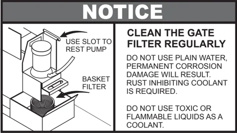
NOTICE
CLEAN THE GATE FILTER REGULARLY
DO NOT USE PLAIN WATER, PERMANENT CORROSION DAMAGE WILL RESULT. RUST INHIBITING COOLANT IS REQUIRED.
DO NOT USE TOXIC OR FLAMMABLE LIQUIDS AS A COOLANT.
Poor Coolant flow can be caused by a dirty filter. To clean the filter, turn off the coolant pump, lift the coolant tank lid and remove the filter. Clean and reinstall filter.
96-8700 rev U June 2008 Maintenance 189
LUBRICATION
| System | Lubricant | Quantity |
|---|---|---|
| Way lube and pneumatics | Mobil Vacatra #2 | 2-2.5 qts |
| Transmission | Mobil SHC 625 | 2.25 liters |
PERIODIC MAINTENANCE
A periodic maintenance page is found within the Current Commands screens titled “Maintenance”. Access the screen by pressing CURNT COMDS and using Page Up or Page Down to scroll to the page.
An item on the list can be selected by pressing the up and down arrow keys. The selected item is then activated or deactivated by pressing Origin. If an item is active, the remaining hours will be displayed, a deactivated item will display, “—” instead.
The maintenance item time is adjusted by using the left and right arrows. Pressing the Origin key will reinstate the default time.
Items are tracked either by the time accumulated while power is on (ON-TIME) or by cycle-start time (CS-TIME). When the time reaches zero the message “Maintenance Due” is displayed at the bottom of the screen (a negative number of hours indicates the hours past due).
This message is not an alarm and does not interfere with machine operation in any way. After the necessary maintenance has been performed, the operator can select that item on the “Maintenance” screen, press the Origin button to deactivate it, then press Origin again to reactivate it with the default number of hours remaining.
Refer to settings 167-186 for additional maintenance defaults. Note that settings 181-186 are used as spare maintenance alerts by keying-in a number. The maintenance number will display on the Current Commands page once a value (time) is added to the setting.
CHUCK MAINTENANCE
Ensure all moving part are thoroughly greased Check for excessive wear on jaws. Check T-nuts for excessive wear. Check front retaining bolts for damage. Chucks should be broken in according to the manufactures’ specifications. Disassemble and inspect chuck once a year.
Refer to chuck manual for disassembly procedures. Check for excessive wear. Check for galling or burnishing. Clean guide ways of contamination, chips and coolant Lubricate chuck before reassembly.
CAUTION! Lack of grease significantly reduces clamping force and can result in chatter, improper clamping, or thrown parts.
Chuck Jaws
Each chuck jaw requires two strokes of grease every 1000 clamp/unclamp cycles, or at least once a week. Use the provided grease gun for chuck lubrication. The Lubrication type is Molybdenum Disulfide Grease (20%-25% moly content).
190 Maintenance 96-8700 rev U June 2008
COOLANT AND COOLANT TANK
Machine coolant must be water-soluble, synthetic oil based or synthetic based coolant/lubricant. Using mineral cutting oils will damage rubber components throughout the machine and void the warranty.
Coolant must have rust inhibitors. Do not use pure water as a coolant; machine components will rust.
Do not use flammable liquids as coolant.
Acidic and high alkaline fluids will damage components throughout the machine.
See safety section and labeling concerning flammable and explosive fluids and materials.
The coolant tank must be thoroughly cleaned periodically, especially for mills equipped with High Pressure Coolant.
Coolant Overview
As the machine runs the water will evaporate which will change the concentration of the coolant. Coolant is also carried out with the parts.
A proper coolant mixture is between 6% and 7%. To top-off coolant only more coolant or deionized water should be used. Be sure that the concentration is still within the range. A refractometer can be used to check the concentration.
Coolant should be replaced at regular intervals. A schedule should be set and held to. This will avoid a build up of machine oil. It will also ensure that coolant with the proper concentration and lubricity will be replaced.
WARNING
When machining castings, sand from the casting process and the abrasive properties of cast aluminum and cast iron will shorten coolant pump life unless a special filter is used in addition to the standard filter. Contact Haas Automation for recommendations.
Machining of ceramics and the like voids all warranty claims for wear and is done entirely at the customer’s risk. Increased maintenance schedules are absolutely required with abrasive swarf. The coolant must be changed more often, and the tank thoroughly cleaned of sediment on the bottom.
Shortened pump life, reduction of coolant pressure and increased maintenance are normal and to be expected in abrasive environments and is not covered by warranty.
LUBRICATION SYSTEM
All machine lubrication is supplied by the external lubrication system. The reservoir is located on the lower rear of the machine (see Figure below). Current lube level is visible in the reservoir. If additional lube needs to be added, remove the cap from the fill port and add lube to proper level.
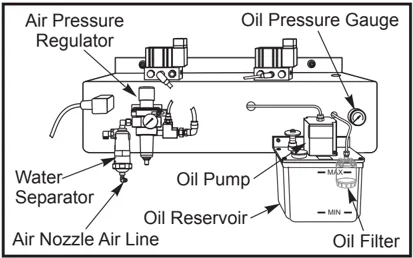
External Lubrication System
WARNING
Do not add lube above the “high” line marked on the reservoir. Do not allow the lube level to go below the “low” line marked on the reservoir as machine damage could result.
96-8700 rev U June 2008 Maintenance 191
Lube Oil Filter
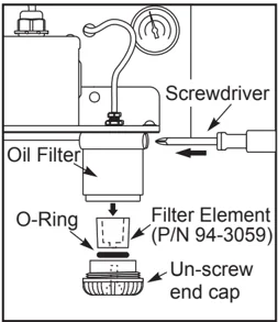
The way lube oil filter element is a 25-micron porous metal filter (94-3059). It is recommended that the filter should be replaced annually or every 2000 hours of machine operation. The filter element is housed in the filter body, which is located in the oil pump reservoir (internal filters).
To change the filter element follow these steps:
- Remove the screws that hold the oil reservoir to the pump body, carefully lower the reservoir and set aside.
- Use a strap wrench, pipe wrench or adjustable pliers to unscrew the end cap (see the figure).
CAUTION! Use a screwdriver or similar tool to stop the filter from turning while the end cap is removed.
- Remove the oil filter element from the filter body once the end cap is removed and clean the inside of the filter housing and the filter end cap as required.
- Install the new oil filter element (P/N 94-3059), O-ring and the end cap. Use the same tools that were used to remove the filter end cap, to tighten it - Do Not Over Tighten.
- Replace the oil reservoir; ensure the gasket seats properly between the reservoir and the top flange.
TRANSMISSION OIL
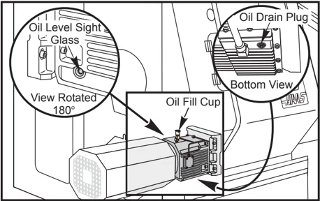
Oil Check
Check the oil level at the sight glass through the opening in the side of the machine as shown in the illustration. Fill as needed through the fill port on top of the gear box.
Oil Change
- Remove the sheet metal necessary to gain access to the transmission, and remove the fourteen (14) SHCS from the oil pan and remove it. Inspect the magnetic drain-plug for signs of metal particles.
- Wipe down the oil pan and reinstall it with a new gasket. Blow downward with an air hose in the vicinity of the access plate to prevent dirt and metal particles from entering the gear case. Remove the access plate.
- Fill the gear case with 2-1/4 liters of Mobil SHC-625 gear oil. Check the sight glass. The level should be 3/4 of the way up when full. Fill as needed.
- Install access plate with new gasket, and run a spindle warm-up and check for leaks.
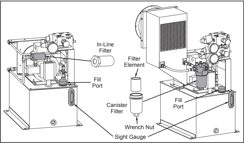
HYDRAULIC POWER UNIT (HPU)
Checking the Oil Level
Observe that the oil level is above the fill line in the sight gauge of the HPU. If not, use the fill port to supply DTE-25 oil to the unit. Fill the unit until oil is observed at the top of the sight glass.
Oil Filter Replacement
In-Line: Unscrew the filter at both ends, remove it from the unit and replace it with a new in-line filter. Discard the old filter.
Canister: Unscrew the canister using the wrench nut at the bottom, remove the filter element and replace it with a new one. Tighten the canister using the wrench nut. Discard the old filter element.
NOTE: If a barfeeder or automatic parts loader is connected to the lathe, remove it to gain access to the Hydraulic Power Unit.
SL-30B \ SL-40 Filters and Replacement Elements
| Filter Manufacturer | Oil Filter Part Number | Replacement Element Part Number |
|---|---|---|
| Pall | 58-1064 | 58-1065 |
| Hydac | 58-1064 | 58-6034 |
| Flow Ezy | 58-1064 | 58-1067 |
96-8700 rev U June 2008 Maintenance 193
CHIP AUGER
During normal operation, most chips are discharged from the machine at the discharge tube. However, very small chips may flow through the drain and collect in the coolant tank strainer. To prevent drain blockage, clean this trap regularly. Should the drain become clogged and cause coolant to collect in the machine's pan, stop the machine, loosen the chips blocking the drain, and allow the coolant to drain. Empty the coolant tank strainer, then resume operation.
Machining Remnants
The end of bar remnant must be collected the same way parts are when using a bar feeder. Remove the remnant by hand or, if using the parts catcher, program it to collect the remnant. Discharge tubes or auger pans that have remnants pushed through them will not be covered under the warranty.
AUXILIARY FILTER ELEMENT REPLACEMENT
Change the filter bag when the filter gauge displays a vacuum level of -5 in. Hg or more. Do not allow the suction to exceed -10 in. Hg or pump damage may occur. Replace with a 25-micron rated filter bag (Haas P/N 93-9130).
Loosen the clamps and open the lid. Use the handle to remove the basket (the filter element will be removed with the basket). Remove the filter element from the basket and discard. Clean the basket. Install a new filter element and replace the basket (with element). Close the lid and secure the clamps.
1000 PSI HPC MAINTENANCE
Before doing any maintenance to the 1000psi system, disconnect the power source; unplug it from the power supply.
Check the oil level on a daily basis. If the oil is low, add oil through the fill cap on the reservoir. Fill the reservoir about 25% full with 5-30W synthetic oil.
WORKLIGHT
Before doing any work on the lathe, turn off power to the machine at the main breaker.
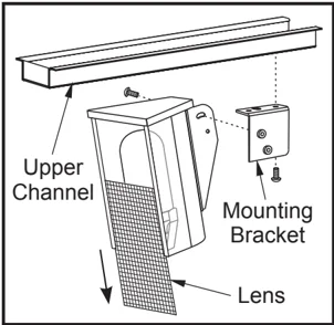
Upper Channel Mounting Bracket Lens Retainer Lens Glass Retainer
NOTE: The power for the worklight comes from the GFI circuit. If the worklight does not turn on, check this first, it can be reset at the side of the control panel.
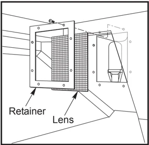
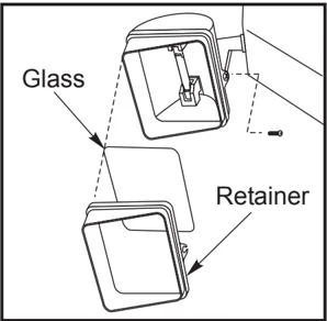
Index
A Accuracy Control 162 Air Requirements 188 Alarms 17 Auto Door 168 Axis Load Monitor 23
B Background Edit 42
C Calculator 17, 24 Cartesian Interpolation 54 Cartesian to Polar Transformation 53 C-Axis 52, 172 Chip Auger 15, 167, 194 Chuck Maintenance 190 Coolant 165, 191 Coolant Tank 191 Corner Rounding/Chamfering 116, 120 Current Commands 56
D Date 24 Direct Numeric Control 36 DIRECTORY LISTING 36 DNC 36
E Electricity Requirements 187 End-Of-Block 18 Enhanced Remote Jog Handle 28 EOB 18 Ethernet 36
G G65 Macro Call 115 G65 Macro Subroutine Call 115
H Hard Drive 36 Help 17 Home 18 HOME G28 20
I Index on the Fly 163
96-8700 rev U June 2008 Index 195
J Jogging, 2-Axis 15
K Keyboard 14 Key Switch 15
L Live Tooling 48, 172 Lubrication System 191
M Machine Data Collect 185 Macro Subroutine Call 115 Macro Subroutine Call (G65) 23 Maintenance Schedule 189 Maximum Corner Rounding 17 Memory Lock Key Switch 164
O Option Try-Out 27 Orient Spindle 165
P Parameters 17 Parentheses 18 Periodic Maintenance 190 Power Up 14
R Remote Jog Handle, Enhanced 28 right slash 18 RS-232 38, 159, 176, 185
S Second Home 15 Settings 17 shift key 18 Sleep Mode 169 Spindle Orientation 165 Square brackets Sub-Program 169 subroutine 169
T Tailstock 15, 166, 182 Taper Compensation 48 Time 24 Tool Geometry 21 Tool Life Display 22
196 Index 96-8700 rev U June 2008
Tool Load Monitor and Display 22 Tool Nose Compensation 58 TOOL OFFSET MESUR 179 Transmission Oil 192
U
USB 36 User M Function 164, 166
V
VDI Installation 52 Visual Quick Code 91
W
Warm-up Compensation 183 Worklight 194 Work Zero Offset 21
X
XZ (2-Axis) Jogging 15
96-8700 rev U June 2008 Index 197