G09 Exact Stop (Group 00)
The G09 code is used to specify a controlled axes stop. It only affects the block in which it is commanded; it is non-modal, it does not affect the following blocks. Machine moves will decelerate to the programmed point before another command is processed.
G10 Set Offsets (Group 00)
G10 allows the programmer to set offsets within the program. Using G10 replaces the manual entry of offsets (i.e. Tool length and diameter, and work coordinate offsets).
-
L Selects offset category.
- L2 Work coordinate origin for COMMON and G54-G59
- L10 Geometry or shift offset
- L1 or L11 Tool wear
- L20 Auxiliary work coordinate origin for G110-G129
-
P Selects a specific offset.
- P1-P50 References geometry, wear or work offsets (L10-L11)
- P51-P100 References shift offsets (YASNAC) (L10-L11)
- P0 References COMMON work coordinate offset (L2)
- P1-P6 G54-G59 references work coordinates (L2)
- P1-P20 G110-G129 references auxiliary coordinates (L20)
- P1-P99 G154 P1-P99 reference auxiliary coordinate (L20)
-
Q Imaginary tool nose tip direction
-
R Tool nose radius
-
*U Incremental amount to be added to X-axis offset
-
*W Incremental amount to be added to Z-axis offset
-
*X X-axis offset
-
*Z Z-axis offset
- indicates optional
Programming Examples
- G10 L2 P1 W6.0 (Move coordinate G54 6.0 units to the right);
- G10 L20 P2 X-10.Z-8. (Set work coordinate G111 to X-10.0, Z-8.0);
- G10 L10 P5 R.032 (Set geometry offset of Tool #5 to .032);
- G10 L10 P5 R.0625 (Set radius of Tool #5 to 1/16");
G14 Sub-Spindle Swap / G15 Cancel (Group 17)
G14 causes the subspindle to become the primary spindle and will react to commands normally used for the main spindle. For example, M03, M04, M05 and M19 will affect the sub-spindle, and M143, M144, M145 and M119 will cause an alarm. Note that G50 will limit the sub-spindle speed, and G96 will set the sub-spindle surface feed value. These G-codes will adjust the subspindle speed when there is motion in the X-axis. G01 Feed Per Rev will feed based on the sub-spindle.
The G14 command will automatically activate Z-axis mirroring. If the Z-axis is already mirrored (Setting 47 or G101) the mirror function will be canceled. G14 is canceled by a G15, an M30, reaching the end of a program, and by pressing Reset.
G17 XY Plane
This code indicates to the controller that programmed circular motion G02 and G03 will be performed in the XY plane. The G17 plane is parallel to X and Y-axes.
G17 code supports G112 Cartesian to Polar transformation. Plane selection codes are modal and remain in effect until another plane is selected.
Programming tool nose radius compensation G41 or G42 will work while using G112 and in the G17 plane.
96-8700 rev U June 2008 G Codes 123
G18 ZX Plane Selection (Group 02) This code indicates to the controller that programmed circular motion G02 and G03 will be performed in the ZX plane. The G18 plane is parallel to Z and X-axes.
G18 is the power on default plane for the HAAS lathe. Plane selection codes are modal and remain in effect until another plane is selected.
G19 YZ Plane (Group 02) This code indicates to the controller that programmed circular motion G02 and G03 will be performed in the YZ plane. The G19 plane is parallel to Y and Z-axes. Plane selection codes are modal and remain in effect until another plane is selected.
G20 Select Inches / G21 Select Metric (Group 06) The G codes G20 (inch) and G21 (mm) codes are used to ensure that the inch/metric selection is set correctly for the program. Selection between inch and metric programming should be done using Setting 9.
G28 Return To Machine Zero, set optional G29 Reference point (Group 00) The G28 code is used to return all axes to machine zero, unless an axis (or axes) is specified, in which case only that axis (or axes) is returned to machine zero. G28 cancels tool length offsets for the following lines of code.
G29 Return from Reference Point (Group 00) The G29 code is used to move the axes to a specific position. The axes selected in this block are moved to the G29 reference point saved in G28, and then moved to the location specified in the G29 command.
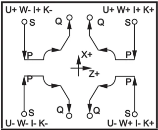
G31 Skip Function (This G-code is optional and requires a probe) (Group 00) F Feed rate *U X-axis incremental motion command *W Z-axis incremental motion command X X-axis absolute motion command Z Z-axis absolute motion command A A-axis absolute motion command B B-axis absolute motion command C C-axis absolute motion command * indicates optional
This G-code moves the axes to the programmed position. It applies only to the block in which G31 is specified. The specified move is started and continues until the position is reached or the probe receives a signal (skip signal). The control will beep when the end of travel is reached.
Do not use Cutter Compensation with a G31. Also see M78 and M79.
G32 Thread Cutting (Group 01) F Feed rate Q Thread Start Angle (optional). See example on the following page. U/W X/Z-axis incremental positioning command. (Incremental thread depth values have to be user specified) X/Z X/Z-axis absolute positioning command. (Thread depth values have to be user specified)
NOTE: Feed rate is equivalent to thread lead. Movement on at least one axis must be specified. Tapered threads have lead in both X and Z. In this case set the feed rate to the larger of the two leads. G99 (Feed per Revolution) must be activ
124 G Codes 96-8700 rev U June 2008
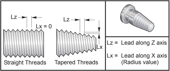
G32 Definition of Lead (Feed Rate) for Straight and Tapered Threads
G32 differs from other thread cutting cycles in that taper and/or lead can vary continuously throughout the entire thread. In addition, no automatic position return is performed at the end of the threading operation.
At the first line of a G32 block of code, axis feed is synchronized with the rotation signal of the spindle encoder. This synchronization remains in effect for each line in a G32 sequence. It is possible to cancel G32 and recall it without losing the original synchronization. This means multiple passes will exactly follow the previous tool path (The actual spindle RPM must be exactly the same between passes).
NOTE: Single Block Stop and Feed Hold are deferred until last line of a G32 sequence. Feed Rate Override is ignored while G32 is active, Actual Feed Rate will always be 100% of programmed feed rate. M23 and M24 have no affect on a G32 operation, the user must program chamfering if needed. G32 must not be used with any G-Code Canned Cycles (i.e.: G71). Do Not change spindle RPM during threading.
CAUTION! G32 is Modal. Always cancel G32 with another Group 01 G-code at the end of a threading operation. (Group 01 G-Codes: G00, G01, G02, G03, G32, G90, G92, and G9
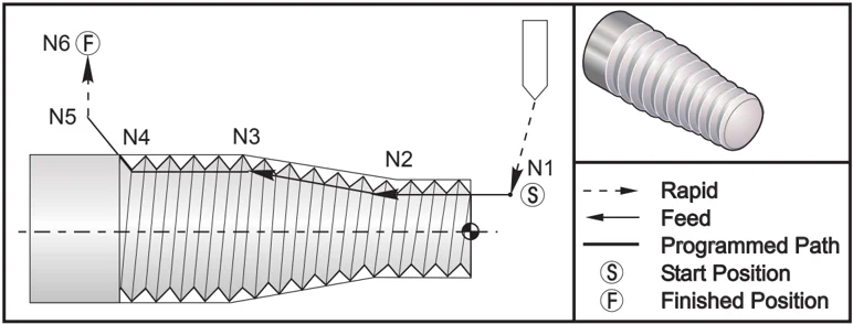
Straight-to-Taper-to-Straight Thread Cutting Cycle
NOTE: Example is for reference only, multiple passes are usually required to cut actual threads.
G32 Program Example ... G97 S400 M03 N1 G00 X0.25 Z0.1 N2 G32 Z-0.26 F0.065 N3 X0.455 Z-0.585
Comments (Constant Surface Speed Cancel) (Rapid to Start Position) (Straight thread, Lead(Lz) = 0.065) (Straight thread blends to tapered thread)
N4 Z-0.9425 N5 X0.655 Z-1.0425 G00 X1.2 G00 Z0.1 ... (Taper thread blends back to straight thread) (Escape at 45 degrees) (Rapid to Finish Position, cancel G32)
Q option example: G32 X-1.99 Z-2. Q60000 F0.2; (60 degree cut) G32 X-1.99 Z-2. Q120000 F0.2; (120 degree cut) G32 X-1.99 Z-2. Q270123 F0.2; (270.123 degree cut)
The following rules apply to the use of Q:
- The start angle (Q) is not a modal value. It must be specified every time it is used. If no value is specified then a zero (0) angle is assumed.
- The angle of threading increment is 0.001 degrees. Do not use a decimal point. A 180° angle must be specified as Q180000 and a 35° angle as Q35000.
- The Q angle must be entered as a positive value from 0 to 360000.
G40 Tool Nose Compensation Cancel (Group 07)
-
X X axis absolute location of departure target
-
Z Z axis absolute location of departure target
-
U X axis incremental distance to departure target
-
W Z axis incremental distance to departure target
-
indicates optional
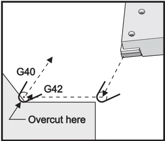
G40 cancels G41 or G42. Programming Txx00 will also cancel tool nose compensation. Cancel tool nose compensation before the end of a program.
The tool departure usually does not correspond with a point on the part. In many cases overcutting or under-cutting can occur.

G40
G41 Tool Nose Compensation (TNC) Left / G42 TNC Right (Group 07)
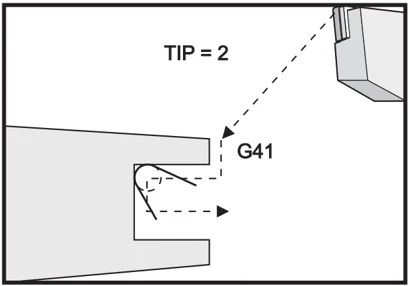
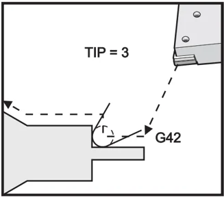
G41 or G42 will select tool nose compensation. G41 moves the tool to the left of the programmed path to compensate for the size of a tool and vice versa for G42. A tool offset must be selected with a Tnnxx code, where xx corresponds to the offsets that are to be used with the tool.
126 G Codes 96-8700 rev U June 2008
TIP = 2
G41
TIP = 3
G42
G41
G42
G50 Set Global coordinate Offset FANUC, YASNAC (Group 00)
U Incremental amount and direction to shift global X coordinate. X Absolute global coordinate shift. W Incremental amount and direction to shift global Z coordinate. Z Absolute global coordinate shift. S Clamp spindle speed to specified value T Apply tool shift offset (YASNAC)
G50 can perform several functions. It can set the global coordinate, it can shift the global coordinate, and it can limit the spindle speed to a maximum value. Refer to the “Coordinate Systems and Offsets” section for a discussion of these.
To set the global coordinate, command G50 with an X or Z value. The effective coordinate will become the value specified in address code X or Z. Current machine location, work offsets and tool offsets are taken into account. The global coordinate is calculated and set.
Example: G50 X0 Z0 (Effective coordinates are now zero);
To shift the global coordinate system, specify G50 with a U or W value. The global coordinate system will be shifted by the amount and direction specified in U or W. The current effective coordinate displayed will change by this amount in the opposite direction. This method is often used to place the part zero outside of the work cell.
Example: G50 W-1.0 (Effective coordinates will be shifted left 1.0);
To set a YASNAC style work coordinate shift, specify G50 with a T value (Setting 33 must be set to YASNAC). The global coordinate is set to the X and Z values in the Tool Shift Offset page. Values for the T address code are, Ttxyy where xx is between 51 and 100 and yy is between 00 and 50. For example, T5101 specifies tool shift index 51 and tool wear index 01; it does not cause tool number 1 to be selected. To select another Ttxyy code must be used outside the G50 block. The following two examples illustrate this method to select Tool 7 using Tool Shift 57 and Tool Wear 07.
Example 1 G51; (Cancel Offsets) T700 M3; (Change to Tool 7, Turn on Spindle) G50 T5707; (Apply Tool Shift and Tool Wear to Tool 7)
Example 2 G51; (Cancel Offsets) G50 T5700; (Apply Tool Shift) T707 M3; (Change to Tool 7 and apply Tool Wear)
96-8700 rev U June 2008 G Codes 127
 000101
N1 G51 (Return to Machine Zero)
N2 G50 T5100; (Offset for Tool 1)
.
.
%
G50 YASNAC Tool Shift
G50 Spindle Speed Clamp G50 can be used to limit the maximum spindle speed. The control will not allow the spindle to exceed the S address value specified in the G50 command. This is used in constant surface feed mode (G96).
N1 G50 S3000 ; (Spindle rpm will not exceed 3000 rpm) N2 G97 M3 ; (Enter constant surface speed cancel, spindle on)
Note: To cancel this command, use another G50 and specify the maximum spindle RPM for the machine.
G51 Cancel Offset (YASNAC) (Group 00) G51 is used to cancel any existing tool wear and work coordinate shift and return to the machine zero position.
Work Coordinate Systems The Haas CNC lathe control supports both YASNAC and FANUC coordinate systems. Work coordinates together with tool offsets can be used to position a part program anywhere within the work area. Also see the Tool Offsets section.
G52 Set Local Coordinate System FANUC (Group 00) This code selects the user coordinate system.
G53 Machine Coordinate Selection (Group 00) This code temporarily cancels work coordinates offsets and uses the machine coordinate system.
G54-59 Select Coordinate System #1 - #6 FANUC (Group 12 ) These codes select one of the six user coordinate systems stored within the offsets memory. All subsequent references to axes' positions will be interpreted in the new coordinate system. Work coordinate system offsets are entered from the Offsets display page.
G61 Exact Stop Modal (Group 15) The G61 code is used to specify exact stop. Rapid and interpolated moves will decelerate to an exact stop before another block is processed. In exact stop, moves will take a longer time and continuous cutter motion will not occur. This may cause deeper cutting where the tool stops.
G64 Exact Stop Cancel G61 (Group 15) The G64 code is used to cancel exact stop. Selects normal cutting mode.
G70 Finishing Cycle (Group 00) The G70 Finishing cycle can be used to finish cut paths that are rough cut with stock removal cycles such as G71, G72 and G73.
P Starting Block number of routine to execute Q Ending Block number of routine to execute
128 G Codes 96-8700 rev U June 2008
 G70
Programming Example G71 P10 Q50 F.012 (rough out N10 to N50 the path) N10 F0.014 ... N50 ... ... ... G70 P10 Q50 (finish path defined by N10 to N50) ...
The G70 cycle is similar to a local subprogram call. However, the G70 requires that a beginning block number (P code) and an ending block number (Q code) be specified.
The G70 cycle is usually used after a G71, G72 or G73 has been performed using the blocks specified by P and Q. Any F, S or T codes with the PQ block are effective. After execution of the Q block, a rapid (G00) is executed returning the machine to the start position that was saved before the starting of the G70. The program then returns to the block following the G70 call. A subroutine in the PQ sequence is acceptable providing that the subroutine does not contain a block with an N code matching the Q specified by the G70 call. This feature is not compatible with FANUC or YASNAC controls.
G71 O.D./I.D. Stock Removal Cycle (Group 00)
- D Depth of cut for each pass of stock removal, positive radius
- F Feed rate to use throughout G71 PQ block
- I X-axis size and direction of G71 rough pass allowance, radius
- K Z-axis size and direction of G71 rough pass allowance P Starting Block number of path to rough Q Ending Block number of path to rough
- S Spindle speed to use throughout G71 PQ block
- T Tool and offset to use throughout G71 PQ block
- U X-axis size and direction of G71 finish allowance, diameter
- W Z-axis size and direction of G71 finish allowance
- R1 YASNAC select Type II roughing
- indicates optional
96-8700 rev U June 2008 G Codes 129
Retraction Setting (73)
G71
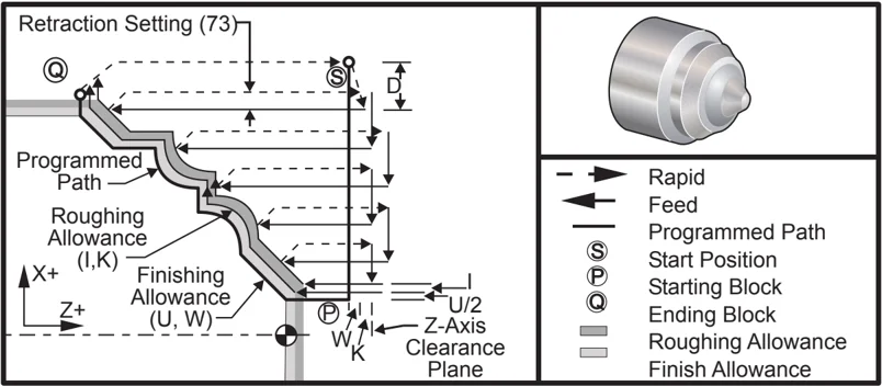
This canned cycle roughs material on a part given the finished part shape. Define the shape of a part by programming the finished tool path and then use the G71 PQ block. Any F,S or T commands on the G71 line or in effect at the time of the G71 is used throughout the G71 roughing cycle. Usually a G70 call to the same PQ block definition is used to finish the shape.
Two types of machining paths are addressed with a G71 command. The first type of path (Type I) is when the X-axis of the programmed path does not change direction. The second type of path (Type II) allows the X-axis to change direction. For both Type I and Type II the programmed path the Z-axis cannot change direction. Type I is selected by having only an X-axis motion in the block specified by P in the G71 call. When both an X-axis and Z-axis motion are in the P block then Type II roughing is assumed. When in YASNAC mode, Type II roughing is selected by including R1 on the G71 command block.
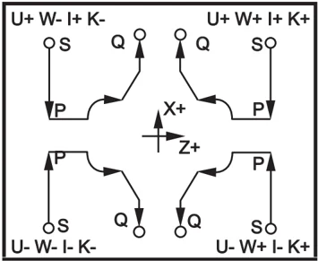
Any one of the four quadrants of the X-Z plane can be cut by specifying address codes D, I, K, U, and W properly.
In the figures, the start position S is the position of the tool at the time of the G71 call. The Z clearance plane is derived from the Z-axis start position and the sum of W and optional K finish allowance.
G71 Address Relationships
130 G Codes 96-8700 rev U June 2008
Type I Details When Type I is specified by the programmer it is assumed that the X-axis tool path does not reverse during a cut. Each roughing pass X-axis location is determined by applying the value specified in D to the current X location. The nature of the movement along the Z clearance plane for each roughing pass is determined by the G code in block P. If block P contains a G00 code, then movement along the Z clearance plane is a rapid mode. If block P contains a G01 then movement will be at the G71 feed rate.
Each roughing pass is stopped before it intersects the programmed tool path allowing for both roughing and finishing allowances. The tool is then retracted from the material, at a 45 degree angle by the distance specified in setting 73. The tool then moves in rapid mode to the Z-axis clearance plane.
When roughing is completed the tool is moved along the tool path to clean up the rough cut. If I and K are specified an additional rough finish cut parallel to the tool path is performed.
Type II Details When Type II is specified by the programmer the X axis PQ path is allowed to vary (for example, the X-axis tool path can reverse direction).
The X axis PQ path must not exceed the original starting location. The only exception is the ending Q block.
Type II roughing, when Setting 33 is set to YASNAC, must include R1 (with no decimal) on the G71 command block.
Type II, when Setting 33 is set to FANUC, must have a reference move, in both the X and Z axis, in the block specified by P.
Roughing is similar to Type I except after each pass along the Z axis, the tool will follow the path defined by PQ. The tool will then retract parallel to the X axis by a distance defined in Setting 73 (Can Cycle Retraction). The Type II roughing method does not leave steps in the part prior to finish cutting and typically results in a better finish.
Troughs
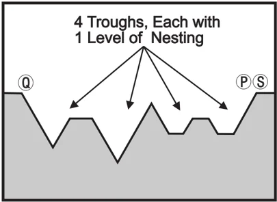
A trough can be defined as a change in direction which creates a concave surface in the material being cut. If successive troughs are on the same level, there can be an unlimited number of troughs. When troughs are within troughs (nested), there can be no more than 10 levels of trough nesting. The following figures illustrate the sequence of roughing cuts (Type I and II) for PQ paths with multiple troughs. All material above troughs is roughed first, followed by the troughs themselves in the direction of Z.
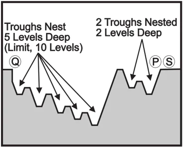
 Path Sequence for Type II Roughing
 Region Sequence for Type II Roughing
Path Sequence for Type II Roughing
Type I and II Tool Retraction
NOTE: An effect of using a Z finish or roughing allowance is the limit between the two cuts on one side of a trough and the corresponding point on the other side of the trough. This distance must be greater than double the sum of the roughing and finish allowances.
For example, if G71 Type 2 path contains the following: ... X-5. Z-5. X-5.1 Z-5.1 X-3.1 Z-8.1 ... The greatest allowance that can be specified is 0.999, since the horizontal distance from the start of cut 2 to the same point on cut 3 is 0.2. If a larger allowance is specified, overcutting will occur.
Cutter compensation is approximated by adjusting the roughing allowance according to the radius and tip type of the tool. Therefore, the limitations that apply to the allowance also apply to the sum of the allowance and the tool radius.
NOTE: If the last cut in the P-Q path is a non-monotonic curve (using a finish allowance) add a short retraction cut; do not use W.
G71 Basic G Code Example
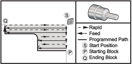
G71 Basic G Code Example
Program Example
% O0070 T101 G50 S2500 G97 S509 M03 G00 G54 X6. Z0.05 G96 S800 G71 P1 Q2 D0.15 U0.01 W0.005 F0.014 N1 G00 X2. G01 Z-3. F0.006 X3.5 G03 X4. Z-3.25 R0.25 G01 Z-6. N2 X6. G70 P1 Q2 M09 G28 M05 M30 %
Description
(G71 Roughing Cycle)
(FINISH PASS)
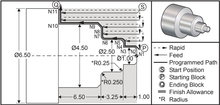
G71 Type 1 O.D./I.D. Stock Removal Example
Program Example
% O0071 T101 (CNMG 432) (Tool change & apply Offsets) G00 G54 X6.6 Z.05 M08 G50 S2000 G97 S636 M03 G96 S750 G71 P1 Q11 D0.15 U0.01 W0.005 F0.012 N1 G00 X0.6634 N2 G01 X1. Z-0.1183 F0.004 N3 Z-1. N4 X1.9376 N5 G03 X2.5 Z-1.2812 R0.2812 N6 G01 Z-3.0312 N7 G02 X2.9376 Z-3.25 R0.2188 N8 G01 X3.9634 N9 X4.5 Z-3.5183 N10 Z-6.5 N11 X6.0 G00 X0 Z0 T100 T202 G50 S2500 G97 S955 M03 G00 X6. Z0.05 M08 G96 S1500 G70 P1 Q11 G00 X0 Z0 T200 M30 %
Description
(FANUC G71 TYPE I EXAMPLE)
(Rapid to Home Position)
(Set Max RPM 2000)
(Spindle On)
(Constant surface speed On)
(Define rough cycle)
P (Begin definition)
(Finish pass .004" Feed)
Q (End definition)
(Rapid to tool change position)
(Finish tool)
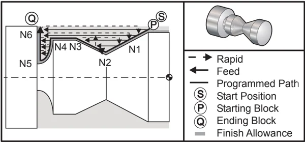
G71 Type II O.D./I.D. Stock Removal Example
134 G Codes 96-8700 rev U June 2008
Program Example % O0001 T101 G97 S1200 M03 ; G00 X2. Z0 G71 P1 Q6 D.035 U.03 W0.01 F0.01 ; N1 G01 X1.5 Z-0.5 F0.004 N2 X1. Z-1. N3 X1.5 Z-1.5 N4 Z-2. N5 G02 X0.5 Z-2.5 R0.5 N6 G01 X2. ; T202 G97 S1500 M03 ; G70 P1 Q6 ; G28 M30 %
Description (YASNAC G71 Type II Example) (Roughing tool)
S (Start position)
P (PQ Path definition)
Q (PQ Path end)
(Finishing tool)
(Finish pass))
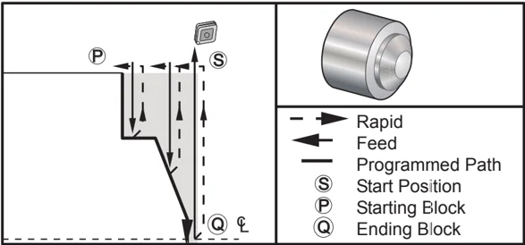
G72 Basic G Code Example
96-8700 rev U June 2008 G Codes 135
Program Example
% O0069 T101 G50 S2500 G97 S509 M03 G54 G00 X6. Z0.05 G96 S800 G72 P1 Q2 D0.075 U0.01 W0.005 F0.012 N1 G00 Z-0.65 G01 X3. F0.006 Z-0.3633 X1.7544 Z0. X-0.0624 N2 G00 Z0.02 G70 P1 Q2 M05 G28 M30 %
Description
(G72 Roughing Cycle)
(Finish Pass)
G71 I.D. Stock Removal Example
NOTE: Be sure the start position of the tool is positioned below the diameter of the part you wish to start roughing out, before defining a G71 on an I.D. with this cycle.
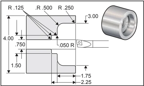
| TOOL | OFFSET | RADIUS | TIP |
|---|---|---|---|
| 4 | 04 | .0 | 0 |
O00088 N2 T404 N3 G97 S2000 M03 N4 G54 G00 X0.7 Z0.1 M08 N5 G71 P6 Q10 U-0.01 W0.005 D0.08 F0.01 (U is minus for G71 I.D. Roughing) N6 G00 X3. N7 G01 Z-1.75 F0.005 N8 X1.5 N9 Z-2.25 F0.003 N10 X0.73 N11 G70 P6 Q10 N12 M09 N13 G28
(Example of using a G71 on an I.D.) (Tool 4 Offset 4) (Rapid to start position below the I.D. stock diameter) (N6 is start of part path geometry defined by P6 in G71 line) (N10 is end of part path geometry defined by Q10 in G71 line) (G70 Defines a finish pass for lines P6 through P10) (To send machine home for a tool change)
G Codes 96-8700 rev U June 2008
G72 End Face Stock Removal Cycle (Group 00)
- D Depth of cut for each pass of stock removal, positive
- F Feed rate to use throughout G72 PQ block
- I X-axis size and direction of G72 rough pass allowance, radius
- K Z-axis size and direction of G72 rough pass allowance P Starting Block number of path to rough Q Ending Block number of path to rough
- S Spindle speed to use throughout G72 PQ block
- T Tool and offset to use throughout G72 PQ block
- U X-axis size and direction of G72 finish allowance, diameter
- W Z-axis size and direction of G72 finish allowance
- indicates optional
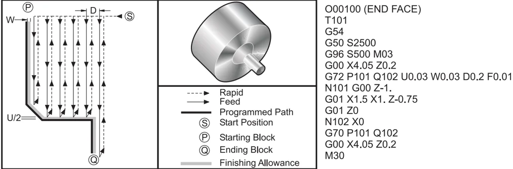
O00100 (END FACE) T101 G54 G50 S2500 G96 S500 M03 G00 X4.05 Z0.2 G72 P101 Q102 U0.03 W0.03 D0.2 F0.01 N101 G00 Z-1. G01 X1.5 X1. Z-0.75 G01 Z0 N102 X0 G70 P101 Q102 G00 X4.05 Z0.2 M30
This canned cycle will remove material on a part given the finished part shape. It is similar to G71 but removes material along the face of a part. Define the shape of a part by programming the finished tool path and then use the G72 PQ block. Any F,S or T commands on the G72 line or in effect at the time of the G72 is used throughout the G72 roughing cycle. Usually a G70 call to the same PQ block definition is used to finish the shape.
Two types of machining paths are addressed with a G72 command. The first type of path (Type I) is when the Z-axis of the programmed path does not change direction. The second type of path (Type II) allows the Z-axis to change direction. For both the first type and the second type of programmed path the X-axis cannot change direction. If Setting 33 is set to FANUC, Type I is selected by having only an X-axis motion in the block specified by P in the G72 call. When both an X-axis and Z-axis motion are in the P block then Type II roughing is assumed. If Setting 33 is set to YASNAC, Type II is specified by including R1 on the G72 command block (Refer to Type II details).
96-8700 rev U June 2008 G Codes 137
G72 End Face Stock Removal Cycle
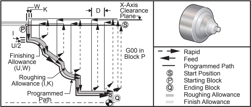
The G72 consists of a roughing phase and a finishing phase. The roughing and finishing phase are handled slightly differently for Type I and Type II. Generally the roughing phase consists of repeated passes along the X-axis at the specified feed rate. The finishing phase consists of a pass along the programmed tool path to remove excess material left by the roughing phase but to leave finish material for a G70 block with perhaps a finishing tool. The final motion in either type is a return to the starting position S.
In the previous figure the start position S is the position of the tool at the time of the G72 call. The X clearance plane is derived from the X-axis start position and the sum of U and optional I finish allowances.
Any one of the four quadrants of the X-Z plane can be cut by specifying address codes I, K, U, and W properly. The following figure indicates the proper signs for these address codes to obtain the desired performance in the associated quadrants.
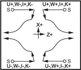
G72 Address Relationships
Type I Details
When Type I is specified by the programmer it is assumed that the Z-axis tool path does not reverse during a cut.
Each roughing pass Z-axis location is determined by applying the value specified in D to the current Z location. The nature of the movement along the X clearance plane for each roughing pass is determined by the G code in block P. If block P contains a G00 code, then movement along the X clearance plane is a rapid mode. If block P contains a G01 then movement will be at the G72 feed rate.
Each roughing pass is stopped before it intersects the programmed tool path allowing for both roughing and finishing allowances. The tool is then retracted from the material, at a 45 degree angle by the distance specified in Setting 73. The tool then moves in rapid mode to the X-axis clearance plane.
When roughing is completed the tool is moved parallel to the tool path to clean up the rough cut. If I and K are specified an additional rough finish cut parallel to the tool path is performed.
Type II Details
When Type II is specified by the programmer the Z axis PQ path is allowed to vary (for example, the Z-axis tool path can reverse direction).
The Z axis PQ path must not exceed the original starting location. The only exception is on the Q block.
Type II roughing when Setting 33 is set to YASNAC, must include R1 (with no decimal) on the G71 command block.
Type II, when Setting 33 is set to FANUC, must have a reference move, in both the X and Z axis, in the block specified by P.
Roughing is similar to Type I except after each pass, along the X axis, the tool will follow the path defined by PQ. The tool will then retract parallel to the Z axis by the distance defined in Setting 73 (Can Cycle Retraction). The Type II roughing method does not leave steps in the part prior to finish cutting and typically results in a better finish.
Note: a side effect of using a X finish or roughing allowance is the limit between the two cuts on one side of a trough and the corresponding point on the other side of the trough. This distance must be greater than double the sum of the roughing and finish allowances.
For example, if G72 type 2 path contains the following: ... X-5. Z-5. X-5.1 Z-5.1 X-8.1 Z-3.1 ...
The greatest allowance that can be specified is 0.999, since the horizontal distance from the start of cut 2 to the start point on cut 3 is 0.2 If a larger allowance is specified, overcutting will occur.
Cutter compensation is approximated by adjusting the roughing allowance according to the radius and tip type of the tool. Thus, the limitations that apply to the allowance also apply to the sum of the allowance and the tool radius.
CAUTION! If the last cut in the P-Q path is a non-monotonic curve, using a finish allowance, add a short retraction cut (do not use U
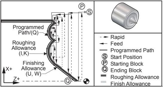
G72 End Face Removal
96-8700 rev U June 2008 G Codes 139
Program Example
% 00722 T101 S1000 M03 G00 G54 X2.1 Z0.1 G72 P1 Q2 D0.06 I0.02 K0.01 U0.0 W0.01 S1100 F0.015 N1 G01 Z-0.46 X2.1 F0.005 X2. G03 X1.9 Z-0.45 R0.2 G01 X1.75 Z-0.4 G02 X1.65 Z-.4 R0.06 G01 X1.5 Z-0.45 G03 X1.3 Z-0.45 R0.12 G01 X1.17 Z-0.41 G02 X1.03 Z-0.41 R0.1 G01 X0.9 Z-0.45 G03 X0.42 Z-0.45 R0.19 G03 X0.2 Z-0.3 R0.38 N2 G01 X0.01 Z0 G70 P1 Q2 M05 G28 M30 %
Description
(G72 Roughing Cycle)
(Finish Pass)
G73 Irregular Path Stock Removal Cycle (Group 00)
| Parameter | Description |
|---|---|
| D | Number of cutting passes, positive number |
| * F | Feed rate to use throughout G73 PQ block |
| I | X-axis distance and direction from first cut to last, radius |
| K | Z-axis distance and direction from first cut to last |
| P | Starting Block number of path to rough |
| Q | Ending Block number of path to rough |
| * S | Spindle speed to use throughout G73 PQ block |
| * T | Tool and offset to use throughout G73 PQ block |
| * U | X-axis size and direction of G73 finish allowance, diameter |
| * W | Z-axis size and direction of G73 finish allowance |
- indicates optional
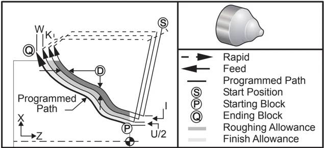
G73 Irregular Path Stock Removal Cycle
The G73 canned cycle can be used for rough cutting of preformed material such as castings. The canned cycle assumes that material has been relieved or is missing a certain known distance from the programmed tool path PQ.
Machining starts from the current position (S), and either rapid or feeds to the first rough cut. The nature of the approach move is based on whether a G00 or G01 is programmed in block P. Machining continues parallel to the programmed tool path. When block Q is reached a rapid departure move is executed to the Start position plus the offset for the second roughing pass. Roughing passes continue in this manner for the number of rough passes specified in D. After the last rough is completed, the tool returns to the starting position S.
Only F, S and T prior to or in the G73 block are in effect. Any feed (F), spindle speed (S) or tool change (T) codes on the lines from P to Q are ignored.
The offset of the first rough cut is determined by (U/2 + I) for the X axis, and by (W + K) for the Z axis. Each successive roughing pass moves incrementally closer to the final roughing finish pass by an amount of (I/(D-1)) in the X axis, and by an amount of (K/(D-1)) in the Z axis. The last rough cut always leaves finish material allowance specified by U/2 for the X axis and W for the Z axis. This canned cycle is intended for use with the G70 finishing canned cycle.
The programmed tool path PQ does not have to be monotonic in X or Z, but care has to be taken to insure that existing material does not interfere with tool movement during approach and departure moves.
The value of D must be a positive integral number. If the D value includes a decimal, an alarm will be generated.
The four quadrants of the ZX plane can be machined if the following signs for U, I, W, and K are used.
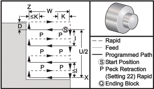
G74 End Face Grooving Cycle, Peck Drilling (Group 00)
- * D Tool clearance when returning to starting plane, positive
- * F Feed rate
- * I X-axis size of increment between peck cycles, positive radius
- K Z-axis size of increment between pecks in a cycle
- * U X-axis incremental distance to furthest peck (diameter)
- W Z-axis incremental distance to total pecking depth
- * X X-axis absolute location of furthest peck cycle (diameter)
- Z Z-axis absolute location total pecking depth
- * indicates optional

G74 End Face Grooving Cycle, Peck Drilling
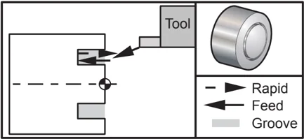
The G74 canned cycle can be used for grooving on the face of a part for peck drilling, or for turning.
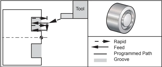
When an X, or U, code is added to a G74 block and X is not the current position, then a minimum of two pecking cycles will occur. One at the current location and another at the X location. The I code is the incremental distance between X axis pecking cycles. Adding an I will perform multiple, evenly spaced, pecking cycles between the starting position S and X. If the distance between S and X is not evenly divisible by I then the last interval will be less than I.
When K is added to a G74 block, then pecking will be performed at each interval specified by K, the peck is a rapid move opposite the direction of feed with a distance as defined by Setting 22. The D code can be used for grooving and turning to provide material clearance when returning to starting plane S.

G74 End Face Grooving Cycle
Program Example
% O0071 T101 G97 S750 M03 G00 X3. Z0.05 G74 Z-0.5 K0.1 F0.01 G28 M30 %
Description
(Rapid to Start position)
(Feed Z-.5 with a .100" peck)
G74 End Face Grooving Cycle (Multiple Pass)
Program Example
% O0074 T101 G97 S750 M03 G00 X3. Z0.05 G74 X1.75 Z-0.5 I0.2 K0.1 F0.01 G28 M30 %
Description
(Rapid to Start position)
(Face grooving cycle multiple pass)
142 G Codes 96-8700 rev U June 2008
G75 O.D./I.D. Grooving Cycle (Group 00)
- D Tool clearance when returning to starting plane, positive
- F Feed rate
- I X-axis size of increment between pecks in a cycle (radius measure)
- K Z-axis size of increment between peck cycles
- U X-axis incremental distance to total pecking depth W Z-axis incremental distance to furthest peck cycle, signed
- X X-axis absolute location total pecking depth, signed diameter Z Z-axis absolute location to furthest peck cycle, signed
- indicates optional
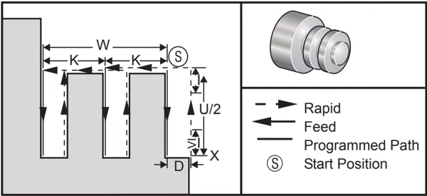
G75O.D. / I.D. Grooving Cycle
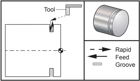
The G75 canned cycle can be used for grooving an outside diameter. When an Z, or W, code is added to a G75 block and Z is not the current position, then a minimum of two pecking cycles will occur. One at the current location and another at the Z location. The K code is the incremental distance between Z axis pecking cycles. Adding a K will perform multiple, evenly spaced, grooves. If the distance between the starting position and the total depth (Z) is not evenly divisible by K then the last interval along Z will be less than K. Note that chip clearance is defined by Setting 22.
96-8700 rev U June 2008 G Codes 143
Program Example
% O0075 T101 G97 S750 M03 G00 X4.1 Z0.05 G01 Z-0.75 F0.05 G75 X3.25 I0.1 F0.01 G00 X5. Z0.1 G28 M30 %
Description
- (Rapid to Clear position)
- (Feed to Groove location)
- (O.D./I.D. Peck grooving single pass)
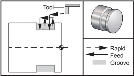
The following program is an example of a G75 program (Multiple Pass):
Program Example
% O0075 T101 G97 S750 M03 G00 X4.1 Z0.05 G01 Z-0.75 F0.05 G75 X3.25 Z-1.75 I0.1 K0.2 F0.01 G00 X5. Z0.1 G28 M30 %
Description
- (Rapid to Clear position)
- (Feed to Groove location)
- (O.D./I.D. Peck groove multiplepass)
G76 Threading Cycle, Multiple Pass (Group 00)
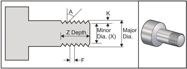
- A Tool nose angle (value: 0 to 120 degrees) Do not use a decimal point D First pass cutting depth F(E) Feed rate, the lead of the thread
- I Thread taper amount, radius measure K Thread height, defines thread depth, radius measure
- P Single Edge Cutting (load constant)
- Q Thread Start Angle (Do not use a decimal point)
- U X-axis incremental distance, start to maximum thread Depth Diameter
- W Z-axis incremental distance, start to maximum thread length
- X X-axis absolute location, maximum thread Depth Diameter
- Z Z-axis absolute location, maximum thread length
- indicates optional
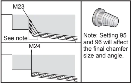
Settings 95 / 96 determine chamfer size / angle; M23 / 24 turn chamfering on / off.
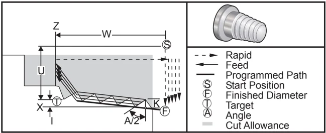
The G76 canned cycle can be used for threading both straight or tapered (pipe) threads.
The height of the thread is defined as the distance from the crest of thread to the root of the thread. The calculated depth of thread (K) will be the value of K less the finish allowance (Setting 86, Thread Finish Allowance) is this amount.
The thread taper amount is specified in I. Thread taper is measured from the target position X, Z at point T to position F. Note that a conventional O.D. taper thread will have a negative I value.
The depth of the first cut through the thread is specified in D. The depth of the last cut through the thread can be controlled with Setting 86.
The tool nose angle for the thread is specified in A. The value can range from 0 to 120 degrees. If A is not used, 0 degrees is assumed.
The F code specifies the feed rate for threading. It is always good programming practice to specify G99 (feed per revolution) prior to a threading canned cycle. The F code also indicates the thread pitch or lead.
At the end of the thread an optional chamfer is performed. The size and angle of the chamfer is controlled with Setting 95 (Thread Chamfer Size) and Setting 96 (Thread Chamfer Angle). The chamfer size is designated in number of threads, so that if 1.000 is recorded in Setting 95 and the feed rate is .05, then the chamfer will be .05. A chamfer can improve the appearance and functionality of threads that must be machined up to a shoulder. If relief is provided for at the end of the thread then the chamfer can be eliminated by specifying 0.000 for the chamfer size in Setting 95, or using M24. The default value for Setting 95 is 1.000 and the default angle for the thread (Setting 96) is 45 degrees.
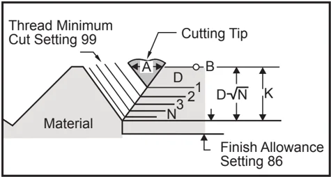
G76 using an "A" Value
Four options for G76 Multiple Thread Cutting is available P1: Single edge cutting, cutting amount constant P2: Double edge cutting, cutting amount constant P3: Single edge cutting, cutting depth constant P4: Double edge cutting, cutting depth constant
P1 and P3 both allow for single edge threading, but the difference is that with P3 a constant depth cut is done with every pass. Similarly, P2 and P4 options allow for double edge cutting with P4 giving constant depth cut with every pass. Based on industry experience, double edge cutting option P2 may give superior threading results.
D specifies the depth of the first cut. Each successive cut is determined by the equation D*sqrt(N) where N is the Nth pass along the thread. The leading edge of the cutter does all of the cutting.To calculate the X position of each pass you have to take the sum of all the previous passes, measured from the start point the X value of each pass
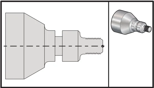
G76 Thread Cutting Cycle, Multiple Pass
Program Example
%
T101
G50 S2500 (Set max RPM select tool geometry)
G97 S1480 M03 (Spindle on select tool one offset one)
G54 G00 X3.1 Z0.5 M08 (Select work coord. and rapid to reference point, coolant on)
G96 S1200 (Constant surface speed ON)
G01 Z0 F0.01 (Position to part Z0)
X-0.04
G00 X3.1 Z0.5
G71P1 Q10 U0.035 W0.005 D0.125 F0.015 (Define roughing cycle)
N1 X0.875 Z0 (Begin tool path)
N2 G01 X1. Z-0.075 F0.006
N3 Z-1.125
N4 G02 X1.25 Z-1.25 R0.125
N5 G01 X1.4
N6 X1.5 Z-1.3
N7 Z-2.25
N8 G02 X1.9638 Z-2.4993 R0.25
N9 G03X2.0172 Z-2.5172 R0.0325
N10 G01 X3. Z-3.5 (End tool path)
G00 Z0.1 M09
G28
N20 (Thread sample program HAAS SL-Series FANUC System)
T505
G50 S2000
G97 S1200 M03 (Threading tool)
G00 X1.2 Z0.3 M08 (Rapid to position)
G76 X0.913 Z-0.85 K0.042 D0.0115 F0.0714 (Threading cycle)
G00X1.5 Z0.5 G28 M09
N30 (HAAS SL-Series FANUC System)
T404
G50 S2500
G97 S1200 M03 (Groove tool)
G54 G00 X1.625 Z0.5 M08
G96 S800
G01 Z-1.906 F0.012
X1.47 F0.006
X1.51
W0.035
G01 W-0.035 U-0.07
G00 X1.51
W-0.035
G01 W0.035 U-0.07
X1.125
G01 X1.51
G00 X3. Z0.5 M09
G28
M30
%
96-8700 rev U June 2008 G Codes 147