Adjusting Zoom Press F2 to display a rectangle (zoom window) indicating the area to be magnified. Use the Page Down key to decrease the size of the zoom window (zooming in), and use the Page Up key to increase the size of the zoom window (zooming out). Use the Cursor Arrow keys to move the zoom window to the desired location and press WRITE/ENTER to complete the zoom and rescale the tool path window. The locator window (small view at the bottom right) shows the entire table with an outline of where the Tool Path window is zoomed. Tool Path window is cleared when zoomed, and the program must be re-run to view the tool path.
The scale and position of the Tool Path window is saved in Settings 65 through 68. Leaving graphics to edit the program and then returning to Graphics will keep the previous scaling in effect.
Press F2 and then the Home key to expand the Tool Path window to cover the entire table.
Z Axis Part Zero Line This feature consists of a horizontal line displayed on the Z-axis bar at the top-right corner of the graphics screen to indicate the position of the current Z-axis work offset plus the length of the current tool. While a program is running, the shaded portion of the bar indicates the depth of Z-axis motion. You can watch the position of the tool tip relative to the Z-axis part zero position as the program runs.
Control Status The lower left portion of the screen displays control status. It is the same as the last four lines of all other displays.
Position Pane The position pane displays axes locations just as it would during a live part run.
F3 / F4 Use these keys to control simulation speed. F3 decrements speed, F4 increments speed.
DATE AND TIME
The control contains a clock and date function. To view the time and date, press the CURNT COMDS button, then Page Up/Down until the date and time appears.
To make adjustments, press Emergency Stop, type the current date (in MM-DD-YYYY format) or current time (in HH:MM format), and press WRITE/ENTER. Reset Emergency Stop when finished.
TABBED HELP / CALCULATOR FUNCTION
Press the HELP/CALC key to display the tabbed help menu. If pressing HELP/CALC calls a pop-up help menu, press HELP/CALC again to access the tabbed menu. Navigate tabs using the Cursor Arrow keys. Press WRITE/ENTER to select tabs, and press CANCEL to back up one tab level. The main tab categories and their sub-tabs are described here:
Help G Codes: View a list of G Codes. M Codes: View a list of M Codes. Features: View a list of new software features. Index: Select this tab to view various help topics. Press WRITE/ENTER to display information about the topic.
Drill Table Displays a drill size table featuring decimal equivalents and tap sizes.
Calculator Calculator functions are available under the third Help tab. Select the calculator mode you want to use from the lower tabs and press WRITE/ENTER to use it.
All of the Calculator functions will do simple add, subtract, multiply, and divide operations. When one of the functions is selected, a calculator window appears with the possible operations (LOAD, +, -, , and /). LOAD is initially highlighted, and the other options can be selected with the left and right cursor arrows. Numbers are entered by typing them in and pressing the Write/Enter key. When a number is entered and LOAD is selected, that number will be entered into the calculator window directly. When a number is entered when one of the other functions (+ - * /) is selected, that calculation will be performed with the number just entered and any number that was already in the calculator window. The calculator will also accept a mathematical expression such as 234-5.2+6/2, evaluating it (doing multiplication and division first) and placing the result, 89.8 in this case, in the window.
Note that data cannot be entered in any field where the label is highlighted. You must clear data in other fields until the label is no longer highlighted in order to change the field directly.
Function Keys: The function keys can be used to copy and paste the calculated results into a section of a program or into another area of the Calculator feature.
F3 In EDIT and MDI modes the F3 key will copy the highlighted triangle/circular milling/tapping value into the data entry line at the bottom of the screen. This is useful when the calculated solution will be used in a program.
In the Calculator function, pressing F3 copies the value in the calculator window to the highlighted data entry for Trig, Circular or Milling/Tapping calculations.
F4 In the Calculator function, this button uses the highlighted Trig, Circular or Milling/Tapping data value to load, add, subtract, multiply, or divide with the calculator.
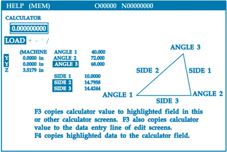
Trigonometry Help Function The Trigonometry calculator page will help solve a triangular problem. Enter the lengths and the angles of a triangle and when enough data has been entered, the control will solve for the triangle and display the rest of the values. Use the Cursor Up/Down buttons to select the value to be entered with Write. For inputs that have more than one solution, entering the last data value a second time will cause the next possible solution to be displayed.

HELP (MEM) O00000 N00000000
CALCULATOR 0.000000000
LOAD + - * /
(MACHINE Y 0.000 in Y 0.000 in Z 3.5179 in
ANGLE 1 40.000 ANGLE 2 72.000 ANGLE 3 68.000
SIDE 1 10.0000 SIDE 2 14.7958 SIDE 3 14.4244
ANGLE 3 SIDE 2 SIDE 1 ANGLE 1 ANGLE 2 SIDE 3
F3 copies calculator value to highlighted field in this or other calculator screens. F3 also copies calculator value to the data entry line of edit screens. F4 copies highlighted data to the calculator field.
96-8700 rev U June 2008 Operation 25
Circular Interpolation Help
The Circular calculator page will help solve a circle problem. You enter the center, radius, angles, start and end points; when enough data has been entered, the control will solve for the circular motion and display the rest of the values. Use the Cursor Up/Down buttons to select the value to be entered with Write. In addition, it will list alternate formats that such a move could be programmed with a G02 or G03. The formats can be selected using the Cursor Up/Down buttons, and the F3 button will import the highlighted line into a program you are editing.
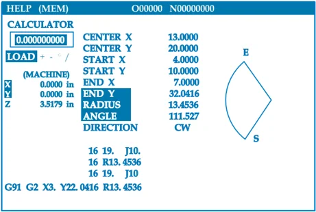
For inputs that have more than one solution, entering the last data value a second time will cause the next possible solution to be displayed. To change the CW value to the CCW value, highlight the CW/CCW column and press the Write/Enter button .
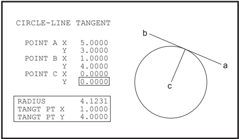
Circle-Line Tangent Calculator
This feature provides the ability to determine points of intersection where a circle and a line meet as tangent. Enter two points, A and B, on a line and a third point, C, away from that line. The control will calculate the point of intersection. The point is where a normal line from point C will intersect with the line AB, as well as the perpendicular distance to that line.
Circle-Circle Tangent Calculator
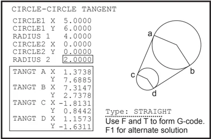
This feature provides the ability to determine points of intersection between two circles or points. The user provides the location of two circles and their radii. The control then calculates all the intersection points that are formed by lines tangent to both circles. Note that for every input condition where there are two disjointed circles, there are up to eight intersection points. Four points are obtained from drawing straight tangents and four points by forming cross tangents. The F1 key is used to toggle between the two diagrams. When "F" is pressed, the control will prompt for the from and to points (A, B, C, etc.) that specify a segment of the diagram. If the segment is an arc, the control will also prompt for C or W (CW or CCW). Sample G code is then displayed at the bottom of the screen. When "T" is entered, the previous to point becomes the new from point and the control prompts for a new to point. To enter the solution (line of code), switch to MDI or Edit and press F3, as the G-code is already on the input line.
Drill/Tap Chart A Drill and Tap Chart is available in the tabbed help menu.
COOLANT LEVEL GAUGE
The coolant level is displayed in the upper right of the screen in MEM mode, or when you press CURNT COMDS. A vertical bar shows the status of the coolant. The display will flash when the coolant reaches a point that could cause intermittent coolant flow.
OPTIONS
200 Hour Control Option Try-Out Options that normally require a unlock code to activate (Rigid Tap, Macros, etc.) can now be activated and deactivated as desired simply by entering the number "1" instead of the unlock code to turn it on. Enter a "0" to turn off the option. An option activated in this manner will be automatically deactivated after a total of 200 power-on hours. Note that the deactivation only occurs when power to the machine is turned off, not while it is running. An option can be activated permanently by entering the unlock code. Note that the letter "T" will be displayed to the right of the option on the parameter screen during the 200 hour period. Note that the safety circuit option is an exception; it can be turned on and off only by unlock codes.
To enter a 1 or 0 into the option you must have Setting 7 (Parameter Lock) turned off and the Emergency Stop button pressed in.
When the option reaches 100 hours the machine will give an alarm warning that the try out time is almost up.
To permanently activate an option, contact your dealer.
Hard Disk Drive, USB and Ethernet Store and transfer data between your Haas machine(s) and a network. Program files are easily transferred to and from memory, and allows DNC of large files at up to 800 blocks per second.
Macros Create subroutines for custom canned cycles, probing routines, operator prompting, math equations or functions, and family-of-parts machining with variables.
Auto Door The auto door option opens the machine doors automatically via the part program. This reduces operator fatigue, or allows for unattended operation when used with a robotic loader
Auto Jet Blast The Auto Jet Blast keeps your workpiece clean. With the doors closed, an M-code activated air blast clears chips and coolant from the chuck and workpiece.
Tool Presetter The manual tool-probe arm swings down for fast tool setting. Touch the tool tip to the probe and offsets are automatically entered.
High Intensity Lighting Halogen lights provide bright, even illumination of the work area for part inspection, job setup and changeovers — ideal for jobs like mold making. Lights turn on and off automatically when doors open and close, or can be activated manually via a switch on the lights.
Steady Rest Provision The steady rest mounting platform provides increased support for long-shaft or narrow-shaft operations. Industry-standard mounting holes accept most aftermarket steady-rest grippers.
M-Function Relays Adds extra relays to increase productivity. These additional M code outputs may be used for activating probes, auxiliary pumps, part loaders, etc.
Remote jog Handle The versatile Haas Remote Jog Handle can be used to move all axes, as well as edit programs, override spindle speeds and feedrates, single-block scroll through programs — and much more.
Tailstock The fully programmable hydraulic tailstock can be activated via the part program or controlled directly by the operator with the standard foot switch.
Parts Catcher The optional part chute rotates into position to catch the finished part and directs it into a bin located on the front door. There’s no need to stop the machine and open the door to retrieve parts.
Barfeeder Designed to boost productivity and streamline turning operations, this servo driven bar feeder is exclusively for Haas CNC lathes. Unique features make setup and operation simple, like a large access door for spindle liner change-out, and a single adjustment for setting bar diameter.
Live Tooling The live tooling option allows you to drive standard VDI axial or radial driven tools to perform such secondary operations as drilling or tapping, both on the face of the part and around the diameter. The main spindle provides indexing in precise increments for part positioning and repeatability.
C-Axis The C-axis provides high-precision, bi-directional spindle motion that is fully interpolated with X and/or Z motion. Cartesian-to-polar interpolation allows programming of face contouring operations using traditional X and Y coordinates.
Memory Lock Key Switch Locks memory to prevent accidental or unapproved program editing by unauthorized personnel. It can also be used to lock settings, parameters, offsets and macro variables.
Spindle Orientation The Spindle Orientation option allows spindle positioning to a specific, programmed angle, using the standard spindle motor and the standard spindle encoder for feedback. This option provides inexpensive, accurate (0.1 degree) positioning.
Auxiliary Filter – This 25-micron #2 bag-type filter system removes contamination and minute particles from the coolant before they can be recirculated through the coolant pump. The filter is mandatory for machines equipped with through-spindle coolant when machining cast iron, cast aluminum and other abrasive materials, and may be used on non-TSC machines as well.
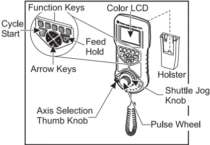
Enhanced Remote Jog Handle (RJH-C) The Enhanced Color Remote Jog Handle (RJH-C) features a color liquid crystal display (LCD) and controls for increased functionality. The RJH-E is configured to control a number of machine functions and settings while providing real-time data from the control via the LCD screen. It also features a magnifier and a high-intensity LED inspection light. Note that the RJH-C is not compatible with lathe software earlier than version 9.

Function Keys Color LCD Cycle Start Feed Hold Arrow Keys Axis Selection Thumb Knob Holster Shuttle Jog Knob Pulse Wheel
28 Operation 96-8700 rev U June 2008
Refer to the section on offsets and machine operation for more information on those topics.
LCD: Displays machine data and the RJH-C interface.
Function Keys (F1-F5): Variable-function keys. Each key corresponds to a label at the bottom of the LCD screen. Pressing a function key will perform or toggle the corresponding menu. Toggled functions are high-lighted when on.
Cycle Start: Starts programmed axis motion.
Feed Hold: Stops programmed axis motion.
Arrow Keys: Used to navigate between menu fields (up/down) and to select pulse jog rates (left/right).
Pulse Wheel: Jogs a selected axis by the selected increment. Works like the jog handle on the control.
Shuttle Jog: Rotates up to 45 degrees CW or CCW from center, and returns to center when released. Used to jog axes at variable speeds. The farther the shuttle jog is rotated from the center position, the faster the axis moves. Allow the shuttle knob to return to center to stop motion.
Axis Select: Used to select any of the available axes for jogging. The selected axis is displayed at the bottom of the screen. The far right position of this selector is used to access the auxiliary menu.
Removing the unit from the cradle powers it on. In Hand Jog, jogging control is turned over from the pendant to the RJH-C (The hand wheel on the pendant is disabled).
Place the RJH-C back in its cradle to power it off and return jogging control to the pendant.
The pulse knob and shuttle knob function as scrollers to change the value of a user-definable field such as tool offset, length, wear, etc.
Built-in "Panic" Function — Press any key during axis motion to instantly stop the spindle and all axis mo-tion. Pressing Feed Hold while the spindle is in motion and the control is in Handle Jog mode will stop the spindle. The message "Button pressed while axis was moving—Reselect Axis" appears on the display. Move the axis selection knob to a different axis to clear.
If the axis selection knob is moved while the shuttle jog is turned, the message "Axis selection changed while axis was moving—Reselect Axis" appears on the display, and all axis motion stops. Move the axis selection knob to a different axis to clear the error.
If the shuttle jog knob is turned from its centered position when the RJH-C is removed from its cradle, or when the control mode is changed to a mode with motion (for instance, from MDI to Handle Jog mode), the message "Shuttle off center—No Axis selected" appears on the display and no axis motion will occur. Move the axis selection knob to clear the error.
If the pulse jog knob is rotated while the shuttle jog knob is in use, the message "Conflicting jog commands— Reselect Axis" appears on the display, and all axis motion stops. Move the axis selection knob to a different axis to clear the error, then back to reselect the previously selected axis.
NOTE: If any of the above errors fail to clear when the axis selection knob is moved, there may be a problem with the shuttle jog knob. Contact Haas service for repair/replace-ment.
If contact between the RJH-C and the control is broken for any reason (cable cut or disconnected, etc.), all axis motion stops. When reconnected, the message "RJH / Control Communication Fault—Reselect Axis" appears on the RJH-C display. Move the axis selection knob to clear the error. If the error does not clear, place the RJH-C in its cradle, wait for it to power off, and then remove from the cradle.
NOTE: This error can also indicate a fault in the SKBIF, the RJH-E, or the wiring. If the error persists, further diagnosis and repair may be necessary.
RJH-C Menus
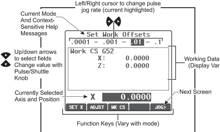
The RJH-C uses four program menus to control manual jogging, set tool length offsets, set work coordinates, and display the current program. The four screens display information differently, but navigating and changing options are always controlled in the same way, as noted in this illustration.
Manual Jogging (Remote Jog Handle)
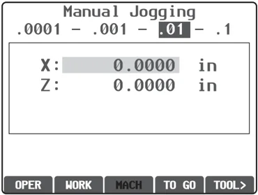
This menu contains a large display of the current machine position. Turning the shuttle jog or pulse knob will move the currently selected axis. Select the jog increment using the left/right arrow keys. The current position coordinate system is highlighted in the function key area of the screen and can be changed by pressing a different function key. To zero the operator position, press the function key under OPER to select the position, then press the function key again (it now reads ZERO).
Tool Offsets (Remote Jog Handle)
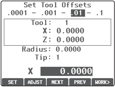
Use this menu to set and check tool offsets. Select fields using the function keys and change values using the pulse knob. Select axes using the thumb knob. The axis line (at the bottom of the display) must be highlighted to jog that axis. Press SET to record the current axis position into the offset table, and use the arrow keys to select the Radius and Tip settings. To make adjustments to table values, select ADJST, use the pulse or shuttle knob to select the amount to increase or decrease the value (use the left and right arrows to change the increment), then press ENTER to apply the adjustment.
CAUTION: Stay clear of the spindle when changing tools.
Set Tool Offsets
- 0001 - .001 - .01 - .1
Tool: 1 X: 0.0000 Z: 0.0000
Radius: 0.0000 Tip: 1
X 0.0000 SET ADJST NEXT PREV WORK>
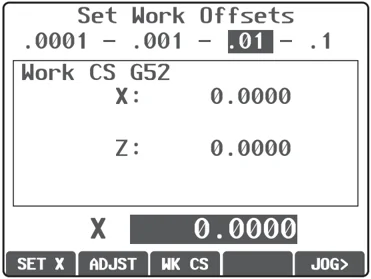
Work Offsets (Remote Jog Handle) Select WK CS to change the work offset G code. Manually jog the selected axis with the shuttle or pulse knob when the axis field at the bottom of the screen is highlighted. Press SET to record the current position of the current axis into the work offset table. Move the axis selector to the next axis and repeat the process to set that axis. To make adjustments to a set value, move the axis selector to the desired axis. Press ADJST and use the pulse knob to increase or decrease the adjustment value, then press ENTER to apply the adjustment.
Set Work Offsets
- 0001 - .001 - .01 - .1
Work CS G52 X: 0.0000 Z: 0.0000
X 0.0000 SET X ADJST WK CS JOG>
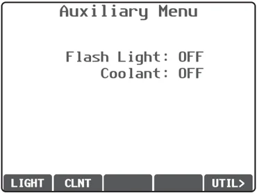
Auxiliary Menu The RJH-C auxiliary menu features controls for machine coolant and the RJH flashlight. Access the menu by moving the axis selector to the far right position (indicated by a page icon molded into the RJH-C case). Toggle the available features by pressing the corresponding function key. Press UTIL to access the utility menu for technician diagnosis, and press AUX to return to the Auxiliary Menu.
Program Display (Run Mode) This mode displays the currently running program. Enter run mode by pressing MEM or MDI on the control pendant. The tab options at the bottom of the screen provide controls for coolant on/off, single block, optional stop, and block delete. Toggled commands such as COOL will appear highlighted when turned on. The CYCLE START and FEED HOLD buttons function just as the buttons on the pendant. Return to jogging by pressing HAND JOG on the control pendant, or place the RJH-E back in the radle to continue running the program from the pendant.
96-8700 rev U June 2008 Operation 31
OPERATION
MACHINE POWER-UP
Turn the machine on by pressing the Power-On button on the pendant.
The machine will go through a self test and display either the Messages screen, if a message was left, or the Alarms screen. In either case, the lathe will have one alarm. Pressing the Reset button a couple times will clear the alarms. If an alarm cannot be cleared, the machine may need servicing. If this is the case, call your dealer.
Once the alarms are cleared, the machine needs a reference point from which to start all operations. This point is called "Home". To home the machine, press the Power-Up Restart button. Note that this will not work for toolroom lathes, subspindle lathes, or automatic parts loader (APL). For these machines, each axis must be homed separately.
CAUTION: Automatic motion will begin once this button is pressed. Keep away from the inside of the machine and the tool changer.
After home is found, the Current Commands page is displayed, and the machine is now ready to run.
PROGRAMMING INTRODUCTION
Manual Data Input (MDI)
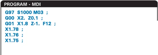
Manual Data Input (MDI) is a means to command automatic CNC moves without using a formal program.
Press the MDI button to enter this mode. Programming code is entered by typing in the commands and pressing Enter at the end of each line. Note that an End of Block (EOB) will be automatically inserted at the end of each line.
 PROGRAM - MDI
G97 S1000 M03 ;
G00 X2. Z0.1 ;
G01 X1.8 Z-1. F12 ;
X1.78 ;
X1.76 ;
X1.75 ;
To edit the MDI program, use the keys to the right of the Edit button. Cursor to the point that is changing, then the different edit functions can be used.
To enter an additional command to the line, type the command and press Enter.
To change a value, use the arrow buttons or the jog handle to highlight the command, enter the new command and press Alter
To delete a command, highlight the command and press Delete.
The Undo key will reverse changes (up to 9 times) that have been made to the MDI program.
The data in MDI is retained after exiting MDI mode and when the machine is turned off. To clear the current MDI commands press the Erase Prog button.
Numbered Programs
To create a new program, press List Prog to enter the program display and the list of programs mode. Enter a program number (Onnnnn) and press Select Prog key or Enter. If the program exists, it will be selected. If it does not yet exist, it will be created. Press Edit to show the new program. A new program will consist of only the program name and an End of Block (;). Numbered programs are retained when the machine is turned off
Basic Editing of MDI and Numbered Programs
The only difference between an MDI program and a numbered program is the O code. To edit an MDI program, simply press MDI. To edit a numbered program, select it, then press Edit.
Type in the program data and press enter. Program data falls into three categories, addresses, comments, or EOBs.
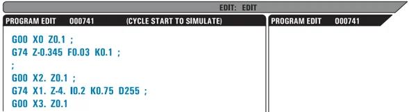
To add program code to an existing program, highlight the area the additional code will go in front of, type in the data, and press Insert key. More than one code; such as X and Z, can be entered before pressing Insert.
Address data is a letter followed by a numeric value. For example: G04 P1.0. The G04 commands a dwell (pause) and the P1.0 is the length (1 second) of the dwell.
Comments can be either alpha or numeric characters, but must be prefaced with parentheses. For example: (1 second dwell). Comments can be a maximum of 80 characters.
Lower-case text can be entered between parentheses (comments). To type lower case text, press the Shift key first (or hold it in) and then the letter or letters.
End of Blocks are entered by pressing the EOB button and are displayed as a semicolon (;). These are used like a carriage return at the end of a paragraph. In CNC programming, an EOB is entered at the end of a string of program code.
An example of a line of code using the three types of commands would be: G04 P1. (1 second dwell);
There is no need to enter spaces between commands. Spaces are automatically entered between elements for ease of reading and editing.
To alter characters, highlight a portion of the program using the arrow keys or the jog handle, enter the replacement code, and press Alter.
To remove characters or commands, highlight them and press Delete.
Use the Undo button to reverse any changes. The Undo button will work for the last nine entries.
There is no save command. The program is saved as each line is entered.
Converting an MDI program to a numbered program
An MDI program can be converted to a numbered program. To do so, cursor to the beginning of the program (or press Home), enter a program name (programs need to be named using the format Onnnnn; the letter "O" followed by up to 5 numbers) and press Alter. This will add the program to the list of programs and clear MDI. To re-access the program, press List Prog and select it.
Searching the program
While in Edit or Mem mode the cursor up and down keys can be used to search the program for specific codes or text. To search for particular character(s), enter the character(s) on the data entry line (i.e. G40) and press the cursor up or down keys. The cursor up key will search for the entered item backwards (toward the start of the program) and the cursor down key will search forward (toward the end of the program).
Deleting Programs
To delete a program, press List Prog. Use the cursor up or down keys to highlight the program number (or type in the program number) and press the Erase Prog key. To delete multiple programs, highlight each program to be deleted and press Write to select them. Press the Erase Prog key to delte the files.
Highlighting ALL at the end of the list and pressing the Erase Prog key will delete all the programs in the list. There are some important programs that you will receive with your machine; they are O02020 (spindle warm up) and O09997, O09999 (Visual Quick Code). You will want to save these programs before erasing all programs. Note that the Undo key will not recover programs that are deleted.
Renaming Programs
After creating a program, the program number can be renamed by changing the name (Onnnnn), in Edit mode, on the first line and pressing the Alter key.
Maximum Program Numbers
If the maximum number of programs (500) is in the controls memory, the message "Dir Full" will display and the program cannot be created.
Program Selection
Enter the program directory by pressing "List Prog"; this will display the stored programs. Scroll to the desired program and press "Select Prog" to select the program. Entering the program name and pressing "Select Prog" will also select a program.
Once "Select Prog" is pressed, the letter "A" appears next to the program name. This program is now active and will be run when the mode is changed to Mem and Cycle Start is pressed. It is also the program that you will see on the Edit display.
The active program will remain active after the machine is turned off.
CNC DATA TRANSFER
Numbered programs can be copied from the CNC control to a personal computer (PC) and back again. It is best if the programs are saved to a file that ends in ".txt". That way, they will be recognized by any PC as a simple text file. Programs can be transferred by many different methods such as RS-232, floppy disk DNC and USB. Settings, offsets and macro variables can be transferred between the CNC and a PC in a similar manner.
Unknown G-Code, if received by the CNC, is converted into a comment, stored in the program, and an alarm is generated. However, the data will still be loaded in to the control. This will also occur when trying to write Macros to the machine without the Macro option installed.
RS-232
RS-232 is one way of connecting the Haas CNC control to another computer. This feature enables the programmer to upload and download programs, settings and tool offsets from a PC.
Programs are sent or received through the RS-232 port (Serial Port 1) located on side of the control box (not the operator's pendant).
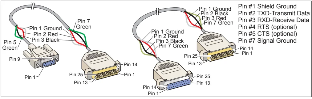
A cable (not included) is necessary to link the CNC control with the PC. There are two styles of RS-232 connections: the 25-pin connector and the 9-pin connector. The 9-pin connector is more commonly used on PCs.

WARNING! One of the biggest causes of electronic damage is a lack of a good ground on both the CNC lathe and the computer. The lack of grounding will damage the CNC, or the computer, or both.
Cable length
The following lists baud rate and the respective maximum cable length. 9,600 baud rate: 100 feet (30 m) RS-232 38,400 baud rate: 25 feet (8 m) RS-232 115,200 baud rate: 6 feet (2 m) RS-232
The settings between the CNC control and the other computer must match. To change the setting in the CNC control, enter the Settings page (press Setng/Graph) and scroll to the RS-232 settings (or enter "11" and press the up or down arrow). Use the up/down arrows to highlight the settings and the left and right arrows to change the values. Press Enter when the proper selection is highlighted.
The settings (and defaults) that control the RS-232 port are: 11 Baud Rate (9600) 12 Parity (Even) 13 Stop Bits (1) 14 Synchronization Xon/Xoff 24 Leader to Punch (None) 25 EOB Pattern (CR LF) 37 Number Data Bits (7)
There are a number of different programs that can link with the Haas control. An example is the Hyper Terminal program that is installed with most Microsoft Windows applications. To change the settings on this program go to the "File" drop down menu at the top left. Choose the "Properties" selection from the menu and then press the "Configure" button. This will open up the port settings; change these to match what is in the CNC control.
To receive a program from the PC, push the LIST PROG key. Move the cursor to the word All and push the RECV RS-232 key and the control will receive all main and sub programs until it receives a "%" indicating end of input. All programs sent to the control from the PC must begin with a line containing a single "%" and must end with a line containing a single "%". Note that when using All, your programs must have a Haas formatted program number (Onnnnn). If you do not have a program number, type in a program number before you push RECV RS-232 and the program will be stored under that number. You can also select an existing program for input and it will be replaced.
To send a program to the PC, use the cursor to select the program and push the SEND RS-232 key. You can select All to send all of the programs in the memory of the control. A setting (Setting 41) can be turned on to add spaces to the RS-232 output and improve the readability of your programs.
Parameters, settings, offsets, and macro variables pages may also be sent individually via RS-232 by selecting the LIST PROG mode, selecting the desired display screen, and pushing the SEND key. They can be received by pushing the RECV key and selecting the file on the PC that is to be received.
The file can be viewed on a PC by adding ".txt" to the file name from CNC control. Open the file on a PC. If an abort message is received, check the set-up between the lathe and the PC and the cable.
96-8700 rev U June 2008 Operation 35
FILE NUMERIC CONTROL (FNC)
A program can be run from its place on the network or from a storage device (USB memory device, floppy disk, hard drive). To run a program from such a location, go to the Device Manager screen (Press List Prog), highlight a program on the selected device and press "Select Prog". The program will be displayed in the active program pane, and an "FNC" next to the program name in List Prog indicates that it is the currently active FNC program. Sub-programs can be called using an M98, provided that the subprogram is in the same directory as the main program. Additionally, the subprogram must be named using the Haas naming convention with case sensitivity, e.g. O12345.nc.
CAUTION: The program can be modified remotely, and the change will take affect the next time the program is run. Subprograms may be changed while the CNC program is running.
Program editing is not allowed in FNC. The program is displayed and can be browsed through, but not edited. Editing can be done from a networked computer or by loading the program into memory.
To run a program in FNC:
- Press List Prog, then navigate to the tabbed menu for the appropriate device (USB, hard drive, Net Share).
- Cursor down to the desired program and press Select Prog. The program will appear in the Active Program pane and can be run directly from the memory device.
To Exit FNC, highlight the program again and press Select Prog, or select a program in CNC memory.
DIRECT NUMERIC CONTROL (DNC)
Direct Numeric Control (DNC) is another method of loading a program into the control. It is the ability to run a program as it is received through the RS-232 port. This feature differs from a program loaded through the RS-232 port in that there is no limit to the size of the CNC program. The program is run by the control as it is sent to the control; the program is not stored in the control.
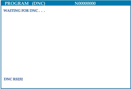
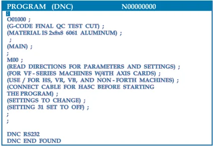
DNC Waiting for Program Program Received from DNC
DNC is enabled using Parameter 57 bit 18 and Setting 55. Turn the parameter bit on (1) and change Setting 55 to On. It is recommended that DNC be run with Xmodem or parity selected because an error in transmission will then be detected and will stop the DNC program without crashing. The settings between the CNC control and the other computer must match. To change the setting in the CNC control, enter the Settings page (press Setng/Graph) and scroll to the RS-232 settings (or enter 11 and press the up or down arrow). Use the up/down arrows to highlight the variables and the left and right arrows to change the values. Press Enter when the proper selection is highlighted. The recommended RS-232 settings for DNC are:
11 Baud Rate Select: 19200 12 Parity Select: NONE 13 Stop Bits:1 14 Synchronization: XMODEM 37 RS-232 Date Bits: 8
DNC is selected by pressing MDI twice at the top of the page. DNC requires a minimum of 8k bytes of user memory available. Checking the amount of free memory on the bottom of the List Programs page.
The program sent to the control must begin and end with a %. The data rate selected (Setting 11) for the RS-232 port must be fast enough to keep up with the rate of block execution of your program. If the data rate is too slow, the tool may stop in a cut. Start sending the program to the control before the Cycle Start button is pushed. Once the message "DNC Prog Found" is displayed, press Cycle Start.
USB / HARD DRIVE / ETHERNET DEVICE MANAGER
The Haas control incorporates a device manager which shows the available memory devices on the machine in a tabbed menu.
Enter the Device Manager by pressing "List Prog". Navigate the tabbed menu using the arrow keys to select the appropriate device tab and press Enter.
When browsing a list of programs within a device tab, use the up/down arrow keys to highlight programs and press Enter to add the highlighted program to the selection.
The following example shows the directory for the USB device. The selected program in memory is shown with an "A". The selected file will also show in the active program display.
Tabbed Menu Navigation
Cursor Arrows: Navigate Tabs WRITE/ENTER: Select a Tab CANCEL: Move Back One Tab Level
Program Selection
Cursor Arrows: Move Selection cursor WRITE/ENTER: Add Program to Selection (A Check Mark is Placed) SELECT PROG: Makes the Selected Program the Active Program ("A") or Selects Program for FNC INSERT: Create New Folder in Current Directory (Type Folder Name, then Insert) ALTER: Rename Folder or Program
Help Mode
Press HELP/CALC to Access the Pop-Up Help Menu. Navigate Using Cursor Arrow Keys. Choose Options for Selected Programs (Copy, Delete, Etc.)
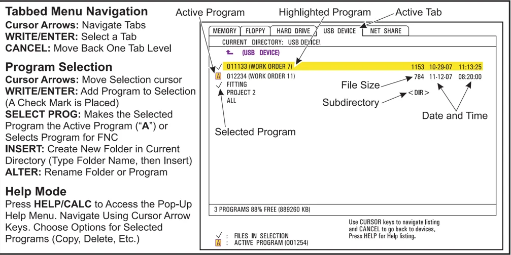
Navigating Directories
To enter a sub-directory, scroll to the sub-directory and press Enter.
To leave a sub-directory, go to the top of the sub-directory and press Enter or press Cancel. Both options will return to the device manager.
Create Directories
Create a new folder by entering a name and pressing "Insert".
To create a new Sub-directory, go to the directory where the new sub-directory will be located, enter a name and press "Insert". Sub-directories are displayed with their name followed by <DIR>.
Copying Files
Highlight a file and press "Enter" to select it. A check mark appears next to the file name. Choose a destination and press F2 to copy the file.
Note that files copied from the control's memory to a device will have the extension ".NC" added to the end of the file name. However the name can be changed by entering a new name, at the destination directory, and then pressing F2.
Duplicating a File
An existing file can be duplicated using the Device manager. Select a file by pressing "Enter", then press "Cancel" to return to the top level tabbed menu. Select the destination device tab, press "Enter", then select the destination directory on the device if applicable. Press F2 to duplicate the selected file, or type a new name and then press F2 to rename the file in the destination directory.
File Naming Convention
File names should be kept to a typical eight-dot-three format. For example: program1.txt. However, some CAD/CAM programs use ".NC" as a file type recognition, which is acceptable.
Files developed in the control will be named with the letter "O" followed by 5 digits. For example O12345.NC.
Renaming
To change the name of a file, highlight the file, type a new name and press "Alter".
Deleting
To delete a program file from a device, highlight the file and press “Erase Prog”.
On-Screen Help
On-Screen help is available by pressing “HELP/CALC”. Select functions from the popup menu and press “Enter” to execute, or use the hot key listed. To exit the Help screen, press the “Cancel” button to return to the device manager.
MACHINE DATA COLLECTION
Machine Data Collection is enabled by Setting 143, which allows the user to extract data from the control using a Q command sent through the RS-232 port (or by using an optional hardware package). This feature is software-based and requires an additional computer to request, interpret and store data from the control. Certain Macro variables can also be set by the remote computer.
Data Collection Using the RS-232 Port
The control only responds to a Q command when Setting 143 is ON. The following output format is used:
<STX> <CSV response> <ETB> <CR/LF> <0x3E>
- STX (0x02) marks the start of data. This control character is for the remote computer.
- CSV is the Comma Separated Variables, one or more data variables separated by commas.
- ETB (0x17) is the end of the data. This control character is for the remote computer.
- CR/LF tells the remote computer data segment is complete and to move to the next line.
- 0x3E Displays the “ > “ prompt.
If the control is busy, it outputs “Status, Busy”. If a request is not recognized, the control outputs “Unknown” and a new prompt “ > “. The following commands can be used:
| Command | Description | Example |
|---|---|---|
| Q100 | Machine Serial Number | >Q100S/N, 12345678 |
| Q101 | Control Software Version | >Q101SOFTWARE, VER M16.01 |
| Q102 | Machine Model Number | >Q102MODEL, VF2D |
| Q104 | Mode (LIST PROG, MDI, etc.) | >Q104MODE, (MEM) |
| Q200 | Tool Changes (total) | >Q200TOOL CHANGES, 23 |
| Q201 | Tool Number in use | >Q201USING TOOL, 1 |
| Q300 | Power-on Time (total) | >Q300P.O. TIME, 00027:50:59 |
| Q301 | Motion Time (total) | >Q301C.S. TIME, 00003:02:57 |
| Q303 | Last Cycle Time | >Q303LAST CYCLE, 000:00:00 |
| Q304 | Previous Cycle Time | >Q304PREV CYCLE, 000:00:00 |
| Q402 | M30 Parts Counter #1 (resettable at control) | >Q402M30 #1, 553 |
| Q403 | M30 Parts Counter #2 (resettable at control) | >Q403M30 #2, 553 |
| Q500 | Three-in-one (PROGRAM, Oxxxxx, STATUS, PARTS, xxxxx) | >Q500STATUS, BUSY |
| Q600 | Macro or system variable | >Q600 801MACRO, 801, 333.339996 |
96-8700 rev U June 2008 Operation 39
The user has the ability to request the contents of any macro or system variable by using the Q600 command, for example, “Q600 xxxx”. This will display the contents of macro variable xxxx on the remote computer. In addition, macro variables #1-33, 100-199, 500-699, 800-999 and #2001 thru #2800 can be “written to” using an “E” command, for example, “Exxxx yyyyyy.yyyyyy” where xxxx is the macro variable and yyyyyy.yyyyyy is the new value. Note that this command should only be used when there are no alarms present.
Data Collection Using Optional Hardware
This method is used to provide machine status to a remote computer, and is enabled with the installation of an 8 Spare M-code relay board (all 8 become dedicated to below functions and cannot be used for normal M-code operation), a power-on relay, an extra set of Emergency Stop contacts, and a set of special cables. Contact your dealer for pricing information on these parts.
Once installed, output relays 40 thru 47, a power-on relay and the Emergency Stop switch are used to communicate the status of the control. Parameter 315 bit 26, Status Relays, must be enabled. Standard spare M-codes are still available for use.
The following machine statuses will be available:
- E-STOP contacts. This will be closed when the E-STOP button is pushed.
- Power ON - 115 VAC. Indicates the control is turned ON. It should be wired to a 115 VAC coil relay for interface.
- Spare Output Relay 40. Indicates that the control is In-Cycle (running.)
- Spare Output Relay 41 and 42:
- 11 = MEM mode & no alarms (AUTO mode.)
- 10 = MDI mode & no alarms (Manual mode.)
- 01 = Single Block mode (Single mode)
- 00 = other modes (zero, DNC, jog, list prog, etc.)
- Spare Output Relay 43 and 44:
- 11 = Feed Hold stop (Feed Hold.)
- 10 = M00 or M01 stop
- 01 = M02 or M30 stop (Program Stop)
- 00 = none of the above (could be single block stop or RESET.)
- Spare Output Relay 45 Feed Rate Override is active (Feed Rate is NOT 100%)
- Spare Output Relay 46 Spindle Speed Override active (Spindle Speed is NOT 100%)
- Spare Output Relay 47 Control is in EDIT mode
ALPHABETICAL ADDRESS CODES
The following is a list of the address codes used in programming the CNC.
A, B, C, U, V, W, X,Y, Z Axis motion – Specifies axis motion (distance or angle). D Depth of cut – Selects the depth of cut for each pass of a stock-removal cycle. E Feedrate, 6 place precision (same as F) – Selects feed rate applied to any interpolating G codes or canned cycles. F Feedrate – Used to enter a feedrate; the value is entered in inches per minute or mm per minute. See Setting 77 for feedrate settings. G, M Preparatory functions – See the chapters on G or M codes. I, J, K Canned cycle and circular optional data – These address characters are used to specify data for some canned cycles and circular motions. They are entered either as inches or mm. L Loop count for repeated cycles – Specifies a repetition count for some canned cycles and auxiliary functions. N Number of block – Identifies or numbers each block of a program (optional). O Program number/name – Used to identify a program. It is followed by a number between 0 and 99999. P Delay time or program number – Used to enter either a time in seconds or a program number for a subroutine call. Q Canned cycle optional data – Used in canned cycles as a positive number in inches/mm between 0 and 100.0, or to identify the final block of a stock-removal path. R Canned cycle and circular optional data – Defines the reference plane for canned cycles and circular interpolation. R is followed by a signed number between -7740.0000 and 7740.0000 for inches or between -196596.000 and 196596.000 for millimeters. S Spindle speed command – Used to specify the spindle speed. T Tool selection code – Used to select the tool number and to specify the tool shift, tool geometry or tool wear values.
PART SETUP
It is necessary to properly secure the part in the chuck. See the chuck or collet manufacturer’s manual for the proper procedure for fixturing a workpiece.
TOOLING
The Tnn code is used to select the tool to be used in a program.
Jog Mode
Jog Mode allows you to jog each of the axes to a desired location. Before jogging the axes it is necessary to home (beginning axes reference point) the axes.
To enter jog mode press the handle jog button, then press one of the desired axes (e.g. X, Z, etc.) and either use the handle jog buttons or the jog handle to move the axes. There are different increment speeds that can be used while in jog mode they are; .0001, .001, .01 and .1.
An optional Remote Jog Handle (RJH) can also be used to jog the axes. The RJH consists of a jog handle, Cycle Start button, Feed Hold button, Axes selection dial and an increment dial.
To jog the axes with the optional Remote Jog Handle (RJH) select the desired axes (X, U, Z, W, B, C or V) using the dial, choose the increment value (X1, X10 or X100) and use the jog handle to move the axes.
Setting the Tool Offset
The next step is to touch off the tools. Doing this defines the distance from the tip of the tool to the side of the part. Enter the Tool Geometry offset page. This should be the first page in the offsets screens; if not, use the page up button until the Tool Geometry page is selected, and press X Dia. Meas. The control will send a prompt to enter the diameter of the part. If the diameter is known, enter the value. You can also touch off the diameter of the part and press Z Face Meas. The control will add the diameter of the part to the location of the X-axis.
Offsets can also be entered manually by choosing one of the offsets pages, moving the cursor to the desired column, typing a number and pressing Write or F1. Pressing F1 will enter the number in the selected column. Entering a value and pressing Write will add the amount entered to the number in the selected column.
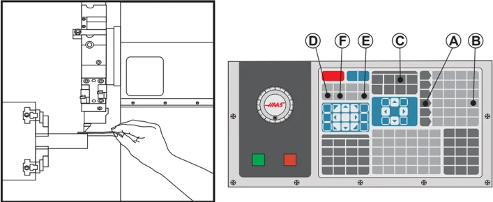
- Load a tool into the tool turret.
- Press the Handle Jog button (A)
- Press .1/100. (B) (The lathe will move at a fast rate when the handle is turned).
- Toggle between the X and Z jog buttons until the tool is touching the side of the part at about a 1/8 of an inch from the front edge.
- Place a sheet of paper between the tool and the part. Carefully move the tool as close as possible, and still be able to move the paper.

- Press Offset (C), the Tool Geometry page should be displayed. If not, page up until the Tool geometry page is displayed.
- Press X Diam. Mesur (D) the operator will then be prompted to add the diameter of the part. This will take the X position located in the bottom left of the screen and the diameter of the part and put it with the position of the tool.
- Back the tool from the part and position the tool tip so that it is touching the face of the stock.
- Press Z Face Meas. (E). This will take the current Z position and write it to the tool offset.
- The cursor will move to the Z-axis location for the tool.
- Press Next Tool (F).
Repeat all of the previous steps for each tool in the program.
Hybrid Turret VDI to BOT Centerline Offset Select Handle Jog and enter the Tool Geometry offset page. Select the centerline value row of and press F2.
SL-20/30 - Type in a value of 4.705 and press Write/Enter to offset the BOT tool position the correct amount from the VDI positions. 4.705 is a rough centerline. Physically measure for the correct centerline, then adjust accordingly (within a range of 4.697 - 4.713).
SL-40 - Type in a value of 5.520 and press Write/Enter to offset the BOT tool position the correct amount from the VDI positions. 5.520 is a rough centerline. Physically measure for the correct centerline, then adjust accordingly (within a range of 5.512 - 5.528).
Additional Tooling Setup There are other tool setup pages within the Current Commands. Press Curnt Comds and then use the Page Up/Down buttons to scroll to these pages.
The first is the page with “Spindle Load” at the top of the page. The programmer can add a tool load limit. The control will reference these values and they can be set to do a specific action should the limitation be reached (see Setting 84).
The second page is the Tool Life page. On this page there is a column called “Alarm”. The programmer can put a value in this column which will cause the machine to stop once the tool has been used that amount of times.
Setting Part (Work piece) Zero Part Zero is a user defined reference point that the CNC control will use to program all moves from.
- Select Tool #1 by pressing MDI, enter “T1” and press Turret Fwd.
- Jog X and Z until the tool is just touching the face of the part.
- Press Z Face Meas. to set part zero.
- Repeat steps 1-3 for each tool used in the program.
Graphics Mode A safe way to troubleshoot a program is by running it in Graphics mode. No movement will occur on the machine, instead the movement will be illustrated on the screen.
Graphics mode can be run from Memory, MDI, DNC or Edit modes. To run a program press the SETNG/GRAPH button until the Graphics page is displayed. In Edit mode, press Cycle Start from the active program pane to enter Graphics mode. To run DNC in graphics, you must select DNC first, then go to graphics display and send your program to the machine’s control (See the DNC section). There are three helpful display features in Graphics mode that can be accessed by pressing one of the function keys (F1, F2, F3 and F4). F1 is the help button, which will give a short description of each of the functions possible in Graphics mode. F2 is the zoom button, which will zoom-in on an area of the graphics screen by using the arrow buttons, Page Up and Page Down to control the zoom level, and pressing the Write button. F3 and F4 are used to control the simulation speed. Note that not all machine functions or motions are simulated in graphics.
Dry Run Operation The Dry Run function is used to check a program quickly without actually cutting parts. Dry Run is selected by pressing the Dry Run button while in MEM or MDI mode. When in Dry Run, all rapid's and feeds are run at the speed selected with the jog speed buttons.
Dry Run can only be turned on or off when a program has completely finished or the Reset button is pressed. Dry Run will still make all of the requested tool changes. The override keys can be used to adjust the Spindle speeds in Dry Run. Note: Graphics mode is just as useful and may be safer as it does not move the axes of the machine before the program is checked (see the previous section on the Graphics function).
Running Programs To run a program one must be loaded on the machine. Once a program is entered and the offsets are set, run the program by pressing the Cycle Start button. It is suggested that the program is run in Graphics mode before doing any cutting.
Background Edit Background Edit allows editing of one program while another program is running.
To activate Background Edit, press Edit until the background edit pane (on the right side of the screen) is active. Select a program to background edit (it must be a program loaded in Memory) from the list and press Write/Enter to begin editing. To select a different program to background edit, press Select Prog from the background edit pane and choose a new program from the list.
All of the changes made during Background Edit will not affect the running program, or its subprograms. The changes will go into affect the next time the program is run.
96-8700 rev U June 2008 Operation 43
The Cycle Start button may not be used while in Background Edit. If the program contains a programmed stop (M00) exit Background Edit (press F4) and then press Cycle Start to resume the program.
Background Edit is activated in Mem mode by pressing the Prgm/Convs button, typing the name (Onnnnn) of a program to edit and pressing F4. If no program name is entered, the Program Review is displayed, which allows the program currently running to be edited. Selecting any other display or pressing F4 exits from Background Edit. While a program is running, press List Prog to display a list of programs in the mill.
All of the changes made during Background Edit will not affect the running program, or its subprograms. The changes will go into affect the next time the program is run.
The Cycle Start button may not be used while in Background Edit. If the program contains a programmed stop (M00) exit Background Edit (press F4) and then press Cycle Start to resume the program.
SUBROUTINES
Subroutines (subprograms) are usually a series of commands that are repeated several times in a program. Instead of repeating the commands many times in the main program, subroutines are written in a separate program. The main program then has a single command that "calls" the subroutine program. A subroutine is called using M97 or M98 and a P address. The P code is the same as the program number (Onnnnn) number of the subroutine to be called.
The subroutines can include an L or repeat count. If there is an L, the subroutine call is repeated that number of times before the main program continues with the next block.
TOOL TURRET OPERATIONS
Low air pressure or insufficient volume will reduce the pressure applied to the turret clamp/unclamp piston and will slow down the turret index time or will not unclamp the turret.
To load or change tools, select MDI mode, and then press Turret Fwd or Turret Rev and the machine will index the turret on tool position. If you enter Tnn prior to pressing Turret Fwd or Turret Rev, the turret will bring the entered tool around to the cutting position.
IMPORTANT: Insert protective caps into any empty turret pockets to protect the pocket from accumulating debris.
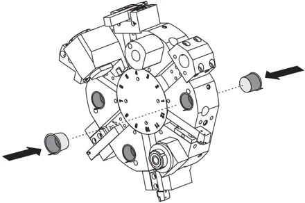
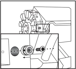
Eccentric Cam Locating Button (SL-Series only)
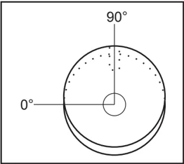
Bolt on turrets are equipped with eccentric locating buttons that allow for fine alignment of ID tool holders to spindle center line.
Mount the tool holder to the turret and align the tool holder to the spindle in the X-axis. Measure the alignment in the Y-axis. If necessary remove the tool holder and use a narrow tool in the cam button hole, to rotate the eccentric to correct misalignment.
The following table gives the result for specific positions of the cam button.
| Rotation | Result |
|---|---|
| 0° | No change |
| 15° | .0018" |
| 30° | .0035" |
| 45° | .0050" |
| 60° | .0060" |
| 75° | .0067" |
| 90° | .0070" |
96-8700 rev U June 2008 Operation 45
TOOL FUNCTIONS
The Tnn00 code is used to select the next tool (nn) and offset (oo). The use of this code differs slightly depending on Setting 33 FANUC or YASNAC coordinate system.
FANUC Coordinate System
T-codes have the format Txxyy where xx specifies the tool number from 1 to the value in Parameter 65; and yy specifies the tool geometry and tool wear indices from 1 to 50. The tool geometry X and Z values are added to the work offsets. If tool nose compensation is used, yy specifies the tool geometry index for radius, taper, and tip. If yy = 00 no tool geometry or wear is applied.
YASNAC Coordinate System
T-codes have the format Tnn00, nn has different meanings depending on whether the T-code is inside or outside a G50 block. The oo value specifies the tool wear from 1 to 50. If tool nose compensation is used, 50+oo specifies the tool shift index for radius, taper, and tip. If oo+00, no tool wear or tool nose compensations are applied.
Outside a G50 block, nn specifies the tool number from 1 to the value in Parameter 65.
Inside a G50 block, nn specifies the tool shift index from 51 to 100. The tool shift X and Z values are subtracted from the work offsets (and thus are of opposite sign than the tool geometries used in the FANUC coordinate system).
Tool Offsets Applied by T0101, FANUC vs YASNAC
Setting a negative tool wear in the tool wear offsets will move the tool further in the negative direction of the axis. Thus, for O.D. turning and facing, setting a negative offset in the X-axis will result in a smaller diameter part and setting a negative value in the Z-axis will result in more material being taken off the face.
NOTE: There is no X or Z motion required prior to performing a tool change and it would waste time in most cases to return X or Z to the home position. However, if your work piece or fixture is quite large, you may need to position X or Z prior to a tool change in order to prevent a crash between the tools and your fixture or part.
Low air pressure or insufficient volume will reduce the pressure applied to the turret clamp/unclamp piston and will slow down the turret index time or will not unclamp the turret.
After Power Up/Restart and Zero Ret, the control will insure that the tool turret is in a normal position. To load or change tools, select MDI mode, and then press Turret Fwd or Turret Rev and the machine will index the turret on tool position. The Curnt Comds display will show what tool is currently in position.
DRAWTUBE OPERATION
The hydraulic unit provides the pressure necessary to clamp a part.
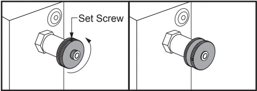
Clamping Force Adjustment Procedure
- Go to Setting 92 on the Settings page and choose either 'I.D.' or 'O.D. Clamping'. Do not do this with a program running.
- Loosen the locking knob at the base of the adjustment knob.
- Turn the adjustment knob until the gauge reads the desired pressure.
- Tighten the locking knob.
Set Screw
46 Programming 96-8700 rev U June 2008
Drawtube Warnings
Warning! Check the workpiece in the chuck or collet after any power loss. A power outage can reduce the clamping pressure on the workpiece, which may shift in the chuck or collet.
Never attach dead length stops to the hydraulic cylinder, damage will result.
Do not machine parts larger than the chuck.
Follow all of the warnings of the chuck manufacturer.
Hydraulic pressure must be set correctly.
See the "Hydraulic System Information" on the machine for safe operation. Setting a pressure beyond the recommendations will damage the machine and/or inadequately hold the workpiece.
Chuck jaws must not protrude beyond the diameter of the chuck.
Improperly or inadequately clamped parts will be ejected with deadly force.
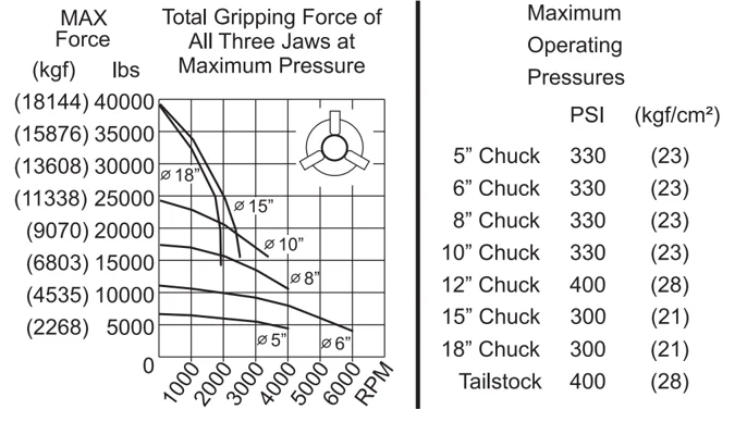
Do not exceed rated chuck RPM.
Higher RPM reduces chuck clamping force. See the following chart.
NOTE: Chucks must be greased weekly and kept free from debris.
CHUCK AND COLLET REPLACEMENT
Chuck Removal
- Move both axes to their zero positions. Remove the chuck jaws.
- Remove the three (3) screws that mount the center cup (or plate) from the center of the chuck and remove the cup.
- Clamp the chuck and remove the six (6) SHCS that mount the chuck to the collet.
- Place a chuck wrench inside the center bore of the chuck and unscrew the chuck from the drawtube. If equipped, removed adapter plate.
Collet Removal
- Loosen the set screw on the side of the spindle nose. Using the collet wrench, unscrew the collet from the spindle nose.
- Remove the six (6) SHCS from the spindle nose and remove it.
- Remove the collet adapter from the drawtube.
 Drive Dog
Draw Tube
Collet Adapter
Set Screw
Set Screw Slot
Collet
Spindle Face
O Ring
Spindle Nose
Collet Wrench
6X SHCS Chuck Adapter Plate 6X SHCS Chuck
Chuck Installation
Note: If necessary, install an adapter plate before installing the chuck
- Clean the face of the spindle and the back face of the chuck. Position the drive dog at the top of the spindle.
- Remove the jaws from the chuck. Remove the center cup or coverplate from the front of the chuck. If available, install a mounting guide into the drawtube and slide the chuck over it.
- Orient the chuck so that one of the guide holes are aligned with the drive dog. Use the chuck wrench to thread the chuck onto the drawtube.
- Screw the chuck all the way onto the drawtube and back it off 1/4 turn. Align the drive dog with one of the holes in the chuck. Tighten the six (6) SHCS.
- Install the center cup or plate with three (3) SHCS .
- Install the jaws. If necessary replace the rear cover plate. This is located on the left side of the machine.
Collet Installation
- Thread the collet adapter into the drawtube.
- Place the spindle nose on the spindle and align one of the holes on the back of the spindle nose with the drive dog.
- Fasten the spindle nose to the spindle with six (6) SHCS.
- Thread the collet onto the spindle nose and align the slot on the on the collet with the set screw on the spindle nose. Tighten the setscrew on the side of the spindle nose.
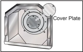
DRAW TUBE COVER PLATE
It is necessary to remove the cover plate at the far end of the drawbar when using a barfeeder. Replace the cover plate anytime bar stock is not being fed automatically.
 Cover Plate
RE-POSITIONING CHUCK JAWS
Re-position chuck jaws when the jaw stroke travel cannot generate sufficient clamp force to hold the material, e.g., when changing to a smaller diameter stock.
The part will not be sufficiently clamped if there is not extra stroke before bottoming out the jaws.