Addressing
7.1 Slot-specific addressing of modules
Preface
For slot-specific addressing (default addressing mode if you have not yet downloaded any configuration data to the CPU), every slot number is assigned a module start address. This is a digital or analog address, based on the type of module.
This section shows you which module start address is assigned to which slot number. You need this information to determine the start addresses of the installed modules.
Maximum assembly and the corresponding module start addresses
The picture below shows the layout of an S7-300 on 4 racks, including the available slots and their module start addresses.
The input and output addresses for I/O modules begin at the same module start address.
Note
On a CPU 31xC system you cannot insert any modules into slot 11 of rack 3. The address range is reserved for the integrated I/O.
127
Addressing
7.1 Slot-specific addressing of modules
The figure below shows the slots of an S7-300 and the corresponding module start addresses:
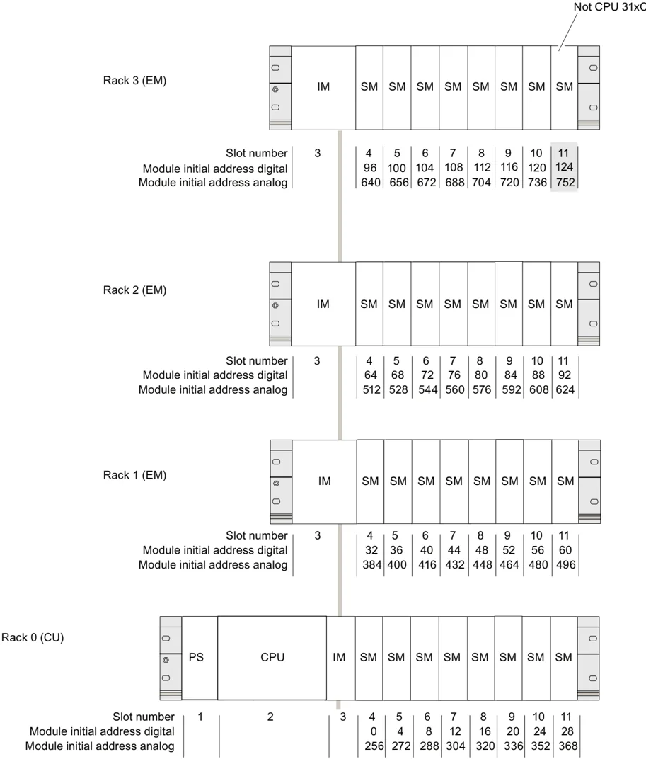
Not CPU 31xC
Rack 3 (EM) IM SM SM SM SM SM SM SM SM Slot number 3 4 5 6 7 8 9 10 11 Module initial address digital 96 100 104 108 112 116 120 124 Module initial address analog 640 656 672 688 704 720 736 752
Rack 2 (EM) IM SM SM SM SM SM SM SM SM Slot number 3 4 5 6 7 8 9 10 11 Module initial address digital 64 68 72 76 80 84 88 92 Module initial address analog 512 528 544 560 576 592 608 624
Rack 1 (EM) IM SM SM SM SM SM SM SM SM Slot number 3 4 5 6 7 8 9 10 11 Module initial address digital 32 36 40 44 48 52 56 60 Module initial address analog 384 400 416 432 448 464 480 496
Rack 0 (CU) PS CPU IM SM SM SM SM SM SM SM SM Slot number 1 2 3 4 5 6 7 8 9 10 11 Module initial address digital 0 4 8 12 16 20 24 28 Module initial address analog 256 272 288 304 320 336 352 368
128
Addressing
7.2 User-specific addressing of modules
7.2 User-specific addressing of modules
7.2.1 User-specific addressing of modules
User-specific addressing
User-specific addressing means that you can assign an address of your choice to any module (SM/FM/CP). The addresses are assigned in STEP 7. There you specify the module start address that forms the basis for all other addresses of the module.
Advantages in user-specific addressing:
- Optimization of available address space as there are no "address gaps" between the modules.
- In your standard software configuration, you can define addresses which are independent of the relevant S7-300 configuration.
Note
You always configure the hardware in HW Config of STEP 7 when using PROFIBUS DP or PROFINET IO field devices. User-specific addressing is automatically set in this case. There is no fixed slot addressing for such a configuration.
129
Addressing 7.2 User-specific addressing of modules
7.2.2 Addressing digital modules
This section describes how to assign addresses to digital modules. You need this information in order to be able to address the channels of the digital module in the user program.
Addresses of digital modules
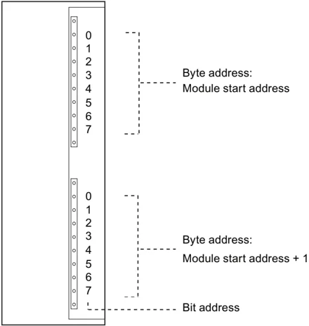
The address of an input or output of a digital module consists of a byte address plus a bit address.
Example: I 1.2
The example consists of:
- input I,
- byte address 1 and
- bit address 2
The byte address is based on the module start address. The bit address is the number printed on the module.
When the first digital module is located in slot 4, its default start address is 0. The start address of each further digital module increments by the count of 4.
The figure below shows you how the scheme by which the addresses of the various channels of a digital module are derived.
130
Addressing 7.2 User-specific addressing of modules
An example of digital modules
The example in the figure below shows which default addresses are derived when a digital module is located in slot 4 (that is, when the module start address is 0). Slot number 3 is not assigned, because the example does not contain an interface module.
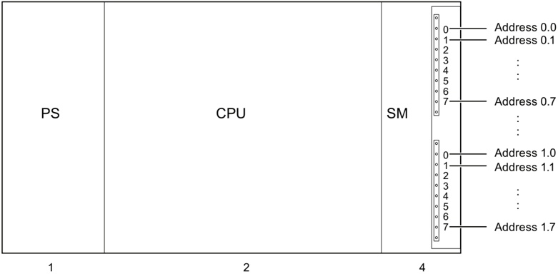
Slot number 1 2 4
7.2.3 Addressing analog modules
This section describes how to address analog modules. You need this information in order to be able to address the channels of the analog modules in your user program.
Addresses of analog modules
The analog input or output channel is always assigned a word address. The channel address is based on the module start address. When the first analog is located in slot 4, its default start address is 256. The start address of each further analog module increments by the count of 16.
An analog I/O module has the same start addresses for its input and output channels.
131
Addressing 7.2 User-specific addressing of modules
An example of analog modules
The example in the figure below shows you which default channel addresses are derived for an analog module located at slot 4. You can see that all analog I/O channels of an analog I/O module are assigned the same start address, which is the module start address.
Slot number 3 is not assigned, because the example does not contain an interface module.
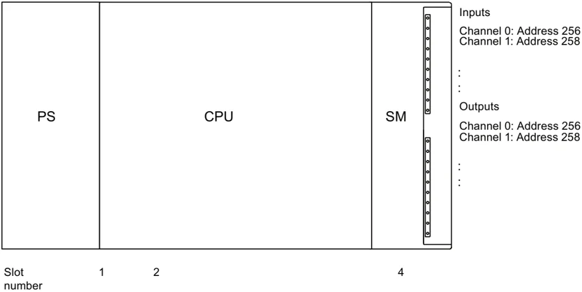
Figure 7-1 I/O addresses of an analog module at slot 4
7.2.4 Addressing the integrated I/Os of CPU 31xC
CPU 312C
The integrated inputs and outputs of this CPU have the following addresses:
Table 7- 1 Integrated I/Os of CPU 312C
Inputs / outputsDefault addressesComments10 digital inputs124.0 to 125.1All digital inputs can be assigned anof which 8 Inputs are forinterrupt function.technological functions:124.0 to 124.7Optional technological functions:6 digital outputs124.0 to 124.5• Countingof which 2 inputs are for• Frequency measurementtechnological functions:• Pulse width modulation124.0 to 124.1
132
CPU 313C
Addresses of the integrated I/Os of this CPU:
Table 7-2 Integrated I/Os of CPU 313C
| Inputs / outputs | Default addresses | Comments |
|---|---|---|
| 24 digital inputs | 124.0 to 126.7of which 12 inputs are for technological functions:124.0 to 125.0125.4 to 125.6 | All digital inputs can be assigned an interrupt function.Optional technological functions:• Counting• Frequency measurement• Pulse width modulation |
| 16 digital outputs | 124.0 to 125.7of which 3 inputs are for technological functions:124.0 to 124.2 | |
| 4 + 1 analog inputs | 752 to 761 | |
| 2 analog outputs | 752 to 755 |
CPU 313C-2 PtP and CPU 313C-2 DP
Addresses of the integrated I/Os of these CPUs:
Table 7-3 Integrated I/Os of CPU 313C-2 PtP/DP
| Inputs / outputs | Default addresses | Comments |
|---|---|---|
| 16 digital inputs | 124.0 to 125.7of which 12 inputs are for technological functions:124.0 to 125.0125.4 to 125.6 | All digital inputs can be assigned an interrupt function.Optional technological functions:• Counting• Frequency measurement• Pulse width modulation |
| 16 digital outputs | 124.0 to 125.7of which 3 inputs are for technological functions:124.0 to 124.2 |
Addressing
7.2 User-specific addressing of modules
CPU 314C-2 PtP and CPU 314C-2 DP
Addresses of the integrated I/Os of these CPUs:
Table 7-4 Integrated inputs/outputs of CPUs 314C-2 PtP and 314C-2 DP
| Inputs / outputs | Default addresses | Comments |
|---|---|---|
| 24 digital inputs | 124.0 to 126.7of which 16 inputs are for technological functions:124.0 to 125.7 | All digital inputs can be assigned an interrupt function.Optional technological functions:• Counting• Frequency measurement• Pulse width modulation• Positioning |
| 16 digital outputs | 124.0 to 125.7of which 4 inputs are for technological functions:124.0 to 124.3 | |
| 4 + 1 analog inputs | 752 to 761 | |
| 2 analog outputs | 752 to 755 |
CPU 314C-2 PN/DP
The integrated inputs and outputs of this CPU have the following addresses:
Table 7-5 Integrated inputs/outputs of the CPU 314C-2 PN/DP
| Inputs/outputs | Default addresses | Comments |
|---|---|---|
| 24 digital inputs | 136.0 to 138.7of which 16 Inputs are for technological functions:136.0 to 137.7 | All digital inputs can be assigned an interrupt function.Optional technological functions:• Counting• Frequency measurement• Pulse width modulation• Positioning |
| 16 digital outputs | 136.0 to 137.7of which 4 inputs are for technological functions:136.0 to 136.3 | |
| 4 + 1 analog inputs | 800 to 809 | |
| 2 analog outputs | 800 to 803 |
Special features
You cannot influence outputs with transfer instructions if they are assigned to technological functions.
I/Os not configured for technological functions can be used as standard I/Os.
7.3 Addressing on PROFIBUS DP
Overview
The corresponding DP slaves must be commissioned for operation on PROFIBUS DP in order to enable addressing of distributed I/O in the user program.
This commissioning includes
- the assignment of PROFIBUS addresses to DP slaves
- the assignment of address ranges to the input/output modules or the slots in order to enable their addressing in the user program. the assignment of a diagnostic address to slots which do not contain user data.
This applies likewise when the CPU is operated as DP slave.
For more information about the commissioning of the CPUs as DP master or DP slave, refer to chapter: Commissioning PROFIBUS DP (Page 166).
User-specific addressing of distributed PROFIBUS IO
Distributed PROFIBUS DP IO requires user-specific addressing.
For more information, refer to chapter: User-specific addressing of modules (Page 129).
Addressing consistent user data areas
The table below shows items to be taken into consideration in terms of communication in a PROFIBUS DP master system when transferring I/O areas with "Total length" consistency.
| Rule for 1 to 32 bytes data consistency on PROFIBUS DP: |
|---|
| The address range of consistent data in the process image is updated automatically. |
| You can also use SFC14 "DPRD_DAT" and SFC15 "DPWR_DAT" to read and write consistent data. SFC14 and SFC15 are required to read and write consistent data of address ranges which are not available in the process image. |
| The length of areas with "Total length" consistency accessed by the SFC must match the programmed range. |
| Direct access to consistent areas is also possible (L PEW or T PAW, for example). |
| PROFIBUS DP supports the transfer of up to 32 bytes of consistent data. |
Addressing 7.4 Addressing PROFINET IO
7.4 Addressing PROFINET IO
Overview
The corresponding I/O devices must be commissioned for operation on PROFINET in order to enable addressing of distributed peripherals on PROFINET IO in the user program.
This commissioning includes
- the assignment of address ranges to the input/output modules or the slots/subslots in order to enable their addressing in the user program. the assignment of a diagnostic address to slots which do not contain user data.
- The definition of device numbers and names for the IO devices
- the definition of I/O device names in order to enable the assignment of IP addresses and access to the IO devices by the CPU 31x PN/DP operated as IO controller.
Note Naming IO devices after "Device replacement without removable medium" If the functionality "Device replacement without removable medium" is configured in HW Config, IO devices can be replaced without the user having to assign a name. To do so, the IO device has to be reset to the state of delivery by using "Reset to factory setting".
Note Use different method to obtain IP address parameters/device names (PROFINET CPUs)
- IP address parameters/device name via DCP:
IP address parameters/device name are assigned by means of DCP (Discovery and Configuration Protocol). This can be achieved in two ways:
- using a setup tool such as PST or STEP 7, for example, via "Edit Ethernet node"
- using the higher-level controller, provided the CPU is operated as an I device.
- IP address parameters/device name via user program: The IP address parameters and/or device names are assigned in the user program of the CPU (using SFB 104)
For more information about the commissioning of the CPU as IO controller, refer to chapter Commissioning PROFINET IO (Page 180)
User-specific addressing of distributed PROFINET IO Distributed peripherals on PROFINET IO require user-specific addressing. For more information, refer to chapter User-specific addressing of modules (Page 129).
136
Addressing
7.5 Assigning IP address parameters and the device name
Addressing consistent user data areas
The table below shows items to be taken into consideration in terms of communication in a PROFINET IO system when transferring I/O areas with "Total length" consistency.
Rule for 1 to 1024 bytes data consistency on PROFINET IO:
The address range of consistent data in the process image is updated automatically. You can also use SFC14 "DPRD_DAT" and SFC15 "DPWR_DAT" to read and write consistent data. SFC14 and SFC15 are required to read and write consistent data of address ranges which are not available in the process image. The length of areas with "Total length" consistency accessed by the SFC must match the programmed range. Direct access to consistent areas is also possible (L PEW or T PAW, for example). PROFINET IO supports the transfer of up to 1024 bytes of consistent data.
7.5 Assigning IP address parameters and the device name
IP address parameters/device name
Similar to any other PROFINET device, the CPU (or its PROFINET interface) also needs the IP address parameters and device name for communication via PROFINET.
The IP address parameters consist of three sections:
- IP address
- Subnet mask
- Router address
Retentivity of IP address parameters and device names
The retentivity of IP address parameters and device names depends on the way it is assigned. The non-retentive, temporary assignment means that:
- IP address parameters and device names are valid until the next POWER OFF or memory reset. After POWER OFF/POWER ON or memory reset, the CPU can be reached at its MAC address only.
- Loading a temporary IP address also deletes non-retentive IP address parameters from memory.
137
Addressing
7.5 Assigning IP address parameters and the device name
Assigning IP address parameters and device names
The following methods are available for the assignment of IP address parameters and device names:
\begin{tabular}{|p{0.25\textwidth}|p{0.45\textwidth}|p{0.25\textwidth}|} \hline \textbf{Assigning IP address parameters and device names} & & \textbf{Retentivity} \ \hline Default method: Permanent assignment in STEP 7 & IP address parameters/device names are assigned permanently in the \textit{STEP 7} configuration. The IP address parameters/device names are saved to retentive memory on the CPU along with the download of configuration data to the CPU. & Data is retentive: \newline \bullet on POWER OFF/POWER ON \newline \bullet after memory reset \newline \bullet after the configuration data was deleted (SDBs) \newline \bullet after the MMC was removed \ \hline Permanent assignment with the settings "Use different method to obtain IP address parameters/device names" & IP address parameters/device names are assigned by means of DCP (Discovery and Configuration Protocol): \newline \bullet Using a setup tool such as PST, or in \textit{STEP 7}, for example, using the "Edit Ethernet nodes" function. \newline \bullet By the higher-level IO controller, provided the CPU is operated as intelligent device with prioritized power up. & \ \hline Temporary assignment in STEP 7 & IP address parameters/device names are assigned by means of DCP (Discovery and Configuration Protocol): \newline \bullet For automatic IP address assignments via "Available nodes" in \textit{STEP 7}, if the CPU does not yet have an IP address. & Data is not retentive \ \hline Temporary assignment with the setting "Use different method to obtain IP address parameters/device names" & IP address parameters/device names are assigned by means of DCP (Discovery and Configuration Protocol): \newline \bullet If not operated with prioritized power up, an intelligent device is assigned the IP address by the higher-level controller. & \ \hline Assignment in the user program & IP address parameters/device names are assigned in the user program using SFB 104. The retentivity of IP address parameters/device names can be specified in a corresponding parameter data record. & Retentivity in accordance with specifications in the parameter data record \ \hline \end{tabular}
138
Addressing 7.5 Assigning IP address parameters and the device name
Resetting retentive IP address parameters and device names
Retentive IP address parameters and device names can be reset as follows:
- With "Reset to factory settings"
- With a firmware update
NOTICE
- The temporary assignment of IP address parameters/device names resets all retentive IP address parameters/device names in memory.
- During the permanent assignment of IP address parameters/device names, the parameters previously saved to retentive memory will be replaced with the new parameters.
NOTICE Reusing devices Always perform a "Reset to factory settings" before you install a device that contains retentive IP address parameters/device names in other subnets/systems, or before you put it on shelf.
Reference
For more information about IP address assignments for the intelligent device, refer to the PROFINET System Description (http://support.automation.siemens.com/WW/view/en/19292127).
139
Addressing 7.5 Assigning IP address parameters and the device name
140
Commissioning
8.1 Overview
This section contains important notes on commissioning which you should strictly observe in order to avoid injury or damage to machines.
Note Your commissioning phase is determined primarily by your application, so we can only offer you general information, without claiming completeness of this topic.
Reference Note the information about commissioning provided in the descriptions of your system components and devices.
8.2 Commissioning procedure
8.2.1 Procedure: Commissioning the hardware
Hardware requirements
- S7-300 is installed.
- S7-300 is wired.
Prepare the interfaces for a networked S7-300 as follows:
- MPI/ PROFIBUS – The MPI/PROFIBUS addresses are set. – The terminating resistors at the segment boundaries are enabled.
- PROFINET – The integrated PROFINET interface of CPU 31x PN/DP is configured in STEP 7 (IP address and device name are set, for example, in HW Config). – The CPU is connected to the subnet.
141
Commissioning
8.2 Commissioning procedure
Recommended procedure: Hardware
The S7-300 system can be very large and extremely complex due to its modular structure and versatile expansion options. It is therefore inappropriate to initially start up an S7-300 with multiple racks and all inserted (installed) modules. Rather, we recommend a step-by-step commissioning procedure.
We recommend the following initial commissioning procedure for an S7-300:
Table 8-1 Recommended commissioning procedure: Hardware
| Tasks | Comments | Information can be found |
|---|---|---|
| An installation and wiring check according to checklist | - | in the chapter: Checklist for commissioning |
| Disconnecting drive aggregates and control elements | This prevents negative effects on your system as a result of program errors.Tip: By redirecting data from your outputs to a data block, you can always check the status at the outputs | - |
| Preparing the CPU | Connecting the PG | in the chapter: Connecting the programming device (PG). |
| Central unit (CU): commission the CPU and power supply, check the LEDs | Commission the CU with inserted power supply module and CPU.First, switch on the expansion devices (EMs) which are equipped with their own power supply module, and then switch on the power supply module of the CU. | in the chapter: Initial power on |
| Check the LED displays on both modules. | in the chapter: Debugging functions, diagnostics and troubleshooting | |
| Reset CPU memory and check the LEDs | - | in the chapter: CPU memory reset by means of mode selector switch |
| CU: commission the remaining modules | Insert additional modules into the CU and commission these, working successively. | in the Module specifications Manual |
| Expansion module (EM): Interconnect | Interconnect the CU with EMs as required: Insert only one send IM into the CU, and insert the matching receive IM into into the EM. | in the chapter: Installation |
| EM: Commissioning | Insert additional modules into the EMs and commission these, working in successively. | See above. |

DANGER
Proceed step-by-step. Do not go to the next step unless you have completed the previous one without error/error message.
Commissioning 8.2 Commissioning procedure
Reference Important notes can also be found in the section Debugging Functions, Diagnostics and Troubleshooting.
See also Procedure: Software commissioning (Page 143)
8.2.2 Procedure: Software commissioning
Requirements
- You must have installed and wired up your S7-300.
- You are using the current programming package of STEP 7 in order to utilize the complete functional scope of your CPU.
- In case of networking of the S7-300 with MPI or PROFIBUS – The MPI/PROFIBUS addresses are configured – You have switched on the terminating resistors at the segment borders.
- In case of networking of the S7-300 with PROFINET – The integrated PROFINET interface of CPU 31x PN/DP is configured in STEP 7 (IP address and device names are set in HW Config) – The CPU is connected to the subnet.
Note Observe the procedure for commissioning the hardware.
143
Commissioning
8.2 Commissioning procedure
Recommended procedure: Software
Table 8- 2 Recommended commissioning procedure - Part II: Software
DANGER
Proceed step-by-step. Do not go to the next step unless you have completed the previous one without error/error message.
Reaction to errors
React to errors as follows:
• Check the system with the help of the check list in the chapter below.
• Check the LED displays on all modules. For information on their meaning, refer to the chapters describing the relevant modules.
• If required, remove individual components to trace the error.

Reference
Important notes can also be found in the section Debugging Functions, Diagnostics and Troubleshooting.
See also
Procedure: Commissioning the hardware (Page 141)
8.3 Commissioning check list
Introduction
After you have installed and wired your S7-300, we advise you to check all previous steps once again.
The check list tables below are a guide for your examination of the S7-300. They also provide cross-references to chapters containing additional information on the relevant topic.
Racks
| Points to be examined are in the manual | S7-300: Installation in chapter |
|---|---|
| Are the rails mounted firmly to the wall, in the frame or in the cabinet? | Configuring, Installation |
| Have you maintained the free space required? | Configuring, Installation |
| Are the cable ducts installed properly? | Configuring |
| Is the air circulation OK? | Installing |
Concept of grounding and chassis ground
| Points to be examined are in the manual | S7-300: Installation in chapter |
|---|---|
| Have you established a low-impedance connection (large surface, large contact area) to local ground? | Configuring, Appendix |
| Are all racks (rails) properly connected to reference potential and local ground (direct electrical connection or ungrounded operation)? | Configuring, Wiring, Appendix |
| Are all grounding points of electrically connected modules and of the load power supply units connected to reference potential? | Configuring, Appendix |
145
Commissioning
8.3 Commissioning check list
Module installation and wiring
| Points to be examined are in the manual | S7-300: Installation in chapter |
|---|---|
| Are all modules properly inserted and screwed in? | Installing |
| Are all front connectors properly wired, plugged, screw-tightened or latched to the correct module? | Installation, Wiring |
Mains voltage
| Points to be examined | S7-300: Installation in chapter | See manual; Section |
|---|---|---|
| Is the correct mains voltage set for all components? | Wiring | Module data |
Power supply module
| Points to be examined | S7-300: Installation in chapter | See manual; Section |
|---|---|---|
| Is the mains plug wired correctly? | Wiring | - |
| Is mains voltage connected? | - | - |
146
Commissioning 8.4 Commissioning the Modules
8.4 Commissioning the Modules
8.4.1 Inserting/replacing a Micro Memory Card
SIMATIC Micro Memory Card (MMC) as memory module
The memory module used on your CPU is a SIMATIC Micro Memory Card. You can set up the SIMATIC Micro Memory Card as a load memory or a portable data medium.
Note A SIMATIC Micro Memory Card must be inserted for CPU operation.
Note The CPU goes into STOP and requests a memory reset when you remove the SIMATIC MMC while the CPU is in RUN state.
CAUTION Data on a SIMATIC Micro Memory Card can be corrupted if you remove the card while it is being accessed by a write operation. You may then have to delete the SIMATIC Micro Memory Card on the PG or format it in the CPU. DO NOT remove the SIMATIC Micro Memory Card when the system is in RUN mode; always shut down power or set the CPU to STOP mode when no PG write access is taking place. When the CPU is in STOP mode and you cannot not determine whether or not a PG is writing to the card (e.g. load/delete block), disconnect the communication lines.
WARNING Make sure that the SIMATIC Micro Memory Card to be inserted contains a user program which is suitable for the CPU (system). The wrong user program may have fatal processing effects.
147


Commissioning 8.4 Commissioning the Modules
Inserting/replacing the SIMATIC Micro Memory Card
- Switch the CPU to STOP mode.
- Is a SIMATIC Micro Memory Card inserted? If yes, ensure that no write operations are running on the PG (such as loading a block). If you cannot ensure this state, disconnect all communication lines of the CPU. Press the ejector and remove the SIMATIC MMC. The frame of the module slot is equipped with an ejector for removing the SIMATIC MMC (see CPU 31xC and CPU 31x Manual, Technical Data, Chapter CPU31x Operator Control and Display Elements). You need a small screwdriver or ball-point pen to eject the SIMATIC Micro Memory Card.
- Insert the ("new") SIMATIC MMC into the card slot with its beveled edge facing the ejector.
- Carefully push the SIMATIC MMC into the CPU slot to engage the interlock.
- Reset CPU memory (see Resetting CPU memory by means of mode selector switch)
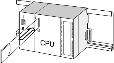
Inserting and removing a SIMATIC MMC when CPU power is switched off
After you replaced a SIMATIC MMC in POWER OFF state, the CPUs
- automatically detect a physically identical SIMATIC MMC with changed content
- automatically detect a new MMC with contents to the previous SIMATIC MMC It automatically performs a CPU memory reset after POWER ON.
Reference
- Chapter Properties of the SIMATIC Micro Memory Card, CPU 31xC and CPU 31x Manual, Technical data
- Chapter Technical data of the SIMATIC Micro Memory Card (MMC), CPU 31xC and CPU 31x Manual, Technical data
148
Commissioning 8.4 Commissioning the Modules
8.4.2 Initial power on
Requirements
- You must have installed and wired up the S7-300.
- Insert the Micro Memory Card into the CPU.
- Your CPU's mode selector switch must be set to STOP.
Initial power on of a CPU with Micro Memory Card Switch on the PS 307 power supply module.
Result:
- The 24 VDC LED is lit on the power supply module.
- On the CPU
- the 5 VDC LED is lit.
- The STOP LED flashes at 2 Hz while the CPU executes an automatic memory reset.
- The STOP LED is lit after memory reset.
149
Commissioning 8.4 Commissioning the Modules
8.4.3 CPU memory reset by means of mode selector switch
When to reset CPU memory
You reset CPU memory
- in order to clear all retentive memory bits, timers and counters, and to initialize work memory with the start values of the retentive DBs in load memory.
- if the new retentive new memory bits, timers and counters downloaded to the CPU user program using the "Download user program to Memory Card" function are liable to cause unwanted reactions.
Reason: the "Download user program to Memory Card" function does not delete any retentive memory areas.
- if the CPU requests a memory reset, indicated by the STOP LED flashing at 0.5 Hz intervals.
Table 8- 3 Possible reasons of a CPU request to reset memory
\begin{tabular}{|l|l|} \hline Causes of a CPU request to reset memory & Special features \ \hline The SIMATIC MMC has been replaced. & – \ \hline RAM error in CPU & – \ \hline Insufficient work memory for loading all user program blocks from a SIMATIC MMC. & CPU with inserted SIMATIC Micro Memory Card: Recursive request of a CPU memory reset. \ \hline Attempts to load faulty blocks; if a wrong instruction was programmed, for example. & For additional information on the behavior of the SIMATIC MMC during CPU memory reset, refer to the CPU 31xC and CPU 31x Manual, Technical data, Memory Reset and Restart \ \hline \end{tabular}
How to reset memory
There are two ways to reset CPU memory:
\begin{tabular}{|l|l|} \hline CPU memory reset using the mode selector switch & CPU memory reset using the PG \ \hline ... is described in this chapter. & ... is only possible when the CPU is in STOP mode (see STEP 7 Online Help). \ \hline \end{tabular}
150
Commissioning 8.4 Commissioning the Modules
Resetting CPU memory using the mode selector switch
The table below shows the steps in resetting CPU memory.
Table 8-4 Procedure for CPU memory reset \begin{tabular}{|l|p{12cm}|} \hline \textbf{Step} & \textbf{Reset CPU memory} \ \hline 1 & Turn the key to STOP position ①. \ \hline 2 & Turn the key to MRES position. Hold the key in this position until the STOP LED lights up for the second time and remains on (this takes 3 seconds) ②. Now release the key. \ \hline 3 & You must turn the key to MRES position again within 3 seconds and hold it there until the STOP LED flashes (at 2 Hz) ③. You can now release the switch. When the CPU has completed memory reset, the STOP LED stops flashing and remains lit. The CPU has reset the memory. \ \hline \end{tabular}
The procedure described earlier is only required to reset CPU memory when the CPU has not requested (indicated by slow flashing of the STOP LED) a memory reset. If the CPU requests a memory reset you only have to briefly set the mode selector switch to the MRES position in order to initiate the memory reset.
The figure below shows how to use the mode selector switch to reset CPU memory:
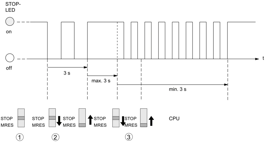
You may have to format the SIMATIC MMC if memory was successfully reset and the CPU once again requests a memory reset (see Formatting the SIMATIC Micro Memory Card).
151