Appendix
A.1 General rules and regulations for S7-300 operation
I ntroduction
Seeing that an S7-300 can be used in many different ways, we can only describe the basic rules for the electrical installation in this document.
WARNING Always observe these basic rules for electrical installation in order to achieve a fully functional S7-300 system.
EMERGENCY-OFF equipment
EMERGENCY-OFF equipment to IEC 204 (corresponds to VDE 113) must remain effective in all operating modes of the plant or system.
System startup after specific events
The table below shows what you have to observe when restarting a plant after specific events.
Table A- 1 System startup after specific events
261

Appendix A.1 General rules and regulations for S7-300 operation
Mains voltage
The table below shows what you have to watch with respect to the mains voltage.
Table A- 2 Mains voltage
\begin{tabular}{|l|l|} \hline In the case of ... & the ... \ \hline Stationary systems or systems without all-pole mains disconnect switch & building installation must contain a mains disconnect switch or a fuse. \ \hline Load power supplies, power supply modules & set rated voltage range must correspond to local mains voltage. \ \hline All circuits of the S7-300 & rated mains voltage fluctuation / deviation must lie within the permitted tolerance (refer to Technical Data of S7-300 modules). \ \hline \end{tabular}
24 VDC power supply
The table below shows what you must observe for the 24 VDC power supply.
Table A- 3 Protection against external electrical interference
\begin{tabular}{|l|l|l|} \hline In the case of ... & you need to observe ... & \ \hline Buildings & external lightning protection. & Install lightning protection (for example, lightning conductors) \ \hline 24 VDC power supply cables, signal cables & internal lightning protection. & \ \hline 24 VDC power supply & safe (electrical) extra-low voltage isolation & \ \hline \end{tabular}
Protection against external electrical interference
The table below shows how you must protect your system against electrical interference or faults.
Table A- 4 Protection against external electrical interference
\begin{tabular}{|l|l|} \hline In the case of ... & Make sure that ... \ \hline All plants or system in which the S7-300 is installed & the plant or system is connected to a protective conductor for the discharge of electromagnetic interference. \ \hline Supply / signal / bus cables & the cable routing and installation is correct. \ \hline Signal and bus cables & a cable/conductor break does not cause undefined plant or system states. \ \hline \end{tabular}
262
Appendix A.2 Protection against electromagnetic interference
A.2 Protection against electromagnetic interference
A.2.1 Basic Points for EMC-compliant system installations
Definition: EMC EMC (electromagnetic compatibility) describes the capability of electrical equipment to operate free of errors in a given electromagnetic environment, without being subject to external influence and without influencing external devices in any way.
Introduction Although your S7-300 and its components are developed for an industrial environment and high electromagnetic compatibility, you should draw up an EMC installation plan before you install the controller taking into consideration all possible sources of interference.
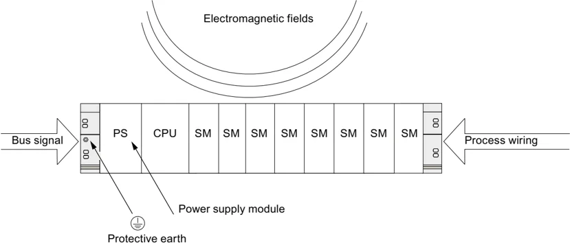
Possible interferences Electromagnetic interference can influence a PLC in various ways:
- Electromagnetic fields having a direct influence on the system
- Interference coupling caused by bus signals (PROFIBUS DP etc.)
- Interference coupling via the system wiring
- Interference influencing the system via the power supply and/or protective ground
The figure below shows the likely paths of electromagnetic interference.
263
Appendix A.2 Protection against electromagnetic interference
Coupling mechanisms
Depending on the emitting media (line or isolated) and the distance between the interference source and the device, four different coupling mechanisms can influence the PLC.
Table A- 5 Coupling mechanisms
Appendix A.2 Protection against electromagnetic interference
A.2.2 Five basic rules for securing EMC
A.2.2.1 1. Basic rule for ensuring EMC
If you comply with theses five basic rules ... you can ensure EMC in many cases!
Rule 1: Large area grounding contact
When you install the automation equipment, make sure that the surfaces of inactive metal parts are properly bonded to chassis ground.
- Bond all passive metal parts to chassis ground, ensuring large area and low-impedance contact.
- When using screw connections on varnished or anodized metal parts, support contact with special contact washers or remove the protective insulating finish on the points of contact.
- Wherever possible, avoid the use of aluminum parts for ground bonding. Aluminum oxidizes very easily and is therefore less suitable for ground bonding.
- Create a central connection between chassis ground and the equipotential grounded/protective conductor system.
A.2.2.2 2. Basic rule for ensuring EMC
Rule 2: Proper cable routing
Always ensure proper cable routing when wiring your system.
- Sort your wiring system into groups (high-voltage/power supply/signal/data cables).
- Always route high-voltage, signal or data cables through separated ducts or in separate bundles.
- Install the signal and data cables as close as possible to grounded surfaces (e.g. supporting beans, metal rails, steel cabinet walls ).
See also
Cable routing inside buildings (Page 275) Outdoor routing of cables (Page 277)
265
Appendix A.2 Protection against electromagnetic interference
A.2.2.3 3. Basic rule for ensuring EMC
Rule 3: Fixing the cable shielding
Ensure proper fixation of the cable shielding.
- Always use shielded data cable. Always connect both ends of the shielding to ground on a large area.
- Analog cables must always be shielded. For the transmission of low-amplitude signals it might prove to be more efficient to have only one side of the shielding connected to ground.
- Directly behind the cable entry in the cabinet or enclosure, terminate the shielding on a large area of the shielding/protective ground bar and fasten it with the help of a cable clamp. Then, route the cable to the module; however, do not connect the shielding once again to ground in this place.
- Connections between the shielding/protective ground conductor bar and the cabinet/enclosure must be of a low impedance.
- Always install shielded data cables in metal/metallized connector housings.
See also Cable shielding (Page 272)
A.2.2.4 4. Basic rule for ensuring EMC
Rule 4: Special EMC measures
Take special EMC measures for particular applications.
- Connect anti-surge elements to all inductive devices not controlled by S7-300 modules.
- For cabinet or cubicle lighting in the immediate range of your controller, use incandescent lamps or interference suppressed fluorescent lamps.
See also How to protect digital output modules against overvoltages caused by inductance (Page 290)
266
Appendix A.2 Protection against electromagnetic interference
A.2.2.5 5. Basic rule for ensuring EMC
Rule 5: Homogeneous reference potential
Create a homogeneous reference potential and ground electrical equipment whenever possible (refer to the section on Equipotential bonding).
- Route your equipotential conductors over a wide area if potential differences exist or are expected between your system components.
- Make sure you carefully direct your grounding measures. Grounding measures protect the controller and its functions.
- Form a star circuit to connect the equipment in your system and the cabinets containing central/expansion units to the grounding/protective conductor system. This prevents the formation of ground loops.
See also
Equipotential bonding (Page 273)
A.2.3 EMC-compliant installation of automation systems
Introduction
Quite often it is the case that interference suppression measures are not taken until corruption of user signals is detected after the controller is actually in operation.
Frequently, the causes of such interference are found in inadequate reference potentials as a result of faulty installation. This section shows you how to avoid such errors.
Inactive metal parts
Inactive parts are referred to as electrically conductive elements, separated from active elements by a basic insulating and only subject to electrical potential if an error occurs.
Installation and ground bonding of inactive metal parts
Bond all inactive metal parts to a large-surface ground when you install the S7-300. Proper ground bonding ensures a homogeneous reference potential for the controller and reduces the effect of interference coupling.
The ground connection establishes an electrically conductive interconnection of all inactive parts. The sum of all interconnected inactive parts is referred to as chassis ground.
This chassis ground must never develop a hazardous potential even if a fault occurs. Therefore, chassis ground must be connected to the protective conductor using cables with an adequate conductor cross-section. To avoid ground loops, physically separate chassis ground elements (cabinets, parts of the building construction or machine) must be bonded to the protective conductor system in a star circuit.
267
Appendix
A.2 Protection against electromagnetic interference
Observe the following for ground connection:
- In the same way as with active elements, exercise meticulous care to interconnect inactive metal elements.
- Always make sure that you have a low-impedance interconnection between metal elements (e.g. large and highly conductive contact surface).
- The protective insulating finish on varnished or anodized metal elements must be pierced or removed. Use special contact washers or completely remove the finish on the point of contact.
- Protect your connecting elements against corrosion (e.g. with a suitable grease).
- Interconnect moving chassis ground elements (e.g. cabinet doors) with flexible ground straps. Always use short ground straps with a large surface (the surface is decisive for the diversion of high-frequency currents).
268
Appendix A.2 Protection against electromagnetic interference
A.2.4 Examples of an EMC-compliant installation: Cabinet configuration
Cabinet configuration The figure below shows a cabinet installation with the measures described above (bonding of inactive metal parts to chassis ground and connecting the cable shielding to ground). This sample applies only to grounded operation. Note the points in the figure when you install your system.
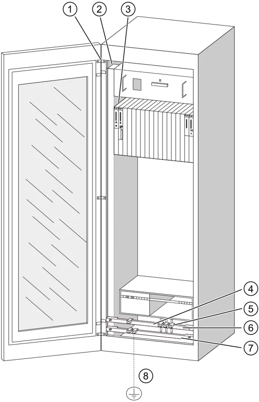
Figure A-1 Example of an EMC compatible cabinet installation
269
Appendix A.2 Protection against electromagnetic interference
Key to installation
The numbers in the following list refer to the numbers in the figure above.
| Number | Identifier | Explanation |
|---|---|---|
| ① | Ground straps | If no large-surface metal-to-metal connections are available, you must either interconnect inactive metal parts (e.g. cabinet doors or mounting plates) or bond them to chassis ground using ground straps. Use short ground straps with a large surface. |
| ② | Supporting bars | Interconnect the supporting bars on a large area to the cabinet walls (metal-to-metal connection). |
| ③ | Mounting the rail | The mounting bar and rack must be interconnected with large-area metal-to-metal connections. |
| ④ | Signal cables | Connect the shielding of signal cables on a large area of the protective conductor/additional shielding conductor bar and fasten them with cable clamps. |
| ⑤ | Cable clamp | The cable clamp must cover a large area of the shielding braid and ensure good contact. |
| ⑥ | Shielding conductor bar | Interconnect the shielding conductor bar on a large surface with the supporting bars (metal-to-metal connection). The cable shielding is terminated on the conductor bar. |
| ⑦ | Protective ground bar | Interconnect the protective conductor bar on a large surface with the supporting bars (metal-to-metal connection). Interconnect the grounding busbar with the protective ground system, using a separate cable (minimum cross-section 10 ²). |
| ⑧ | Cable to the protective ground system (equipotential ground) | Interconnect the cable on a large area with the protective ground system (equipotential ground). |
A.2.5 Examples of an EMC-compliant installation: Wall mounting
Wall mounting
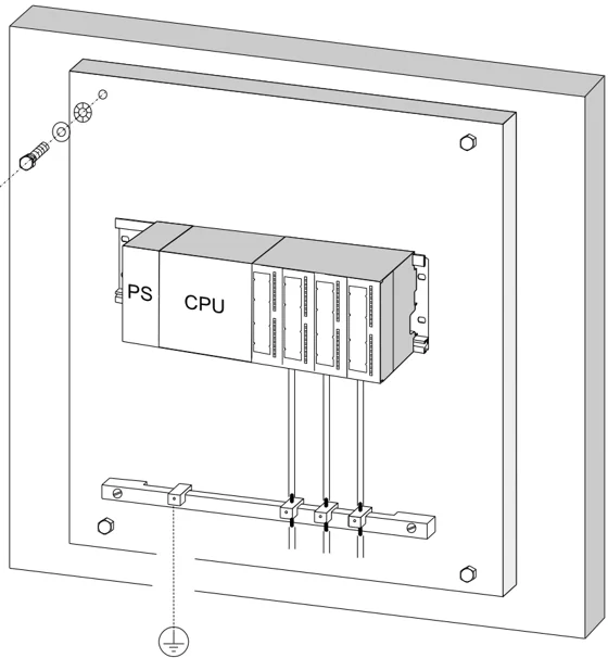
When operating your S7 in a low-noise environment that conform with permitted ambient conditions (see Appendix Ambient conditions), you can also mount your S7 in frames or to the wall.
Interference coupling must be diverted to large metal surfaces. Therefore, always mount standard profile/shielding/protective conductor rails on metal parts of the construction. Steel sheet panels reference potential surfaces have been found especially suitable for wall-mounting.
Provide a shielding conductor bar for connecting your cable shielding. This shielding conductor bar can also be used as protective ground bar.
Appendix A.2 Protection against electromagnetic interference
Reference for ambient conditions
For information on ambient conditions, refer to the S7-300 Automation System, Module data Reference Manual.
Please note
- When mounting on varnished or anodized metal parts, use special contact washers or remove the insulating layers.
- Provide a large-surface and low-impedance metal-to-metal connection for fastening the shielding/protective protective ground bar.
- Always touch-protect live mains conductors.
The figure below shows an example of EMC compatible wall-mounting of an S7.
271
Appendix A.2 Protection against electromagnetic interference
A.2.6 Cable shielding
Purpose of the shielding A cable is shielded to attenuate the effects of magnetic, electrical and electromagnetic interference on the cable.
Operating principle Interference currents on cable shielding is diverted to ground conductive interconnection between the shielding and the cabinet. To avoid interference as a result of these currents, it is imperative to provide a low-impedance connection to the protective conductor.
Suitable cables Whenever possible, use cables equipped with a shielding braid. Shielding density should be at least 80 %. Avoid cables with film shielding, because the film can be easily damaged by tensile or pressure stress, thus reducing its shielding effect.
Handling of the shielding Note the following points on handling the shielding:
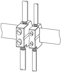
- Always use metal clamps to mount shielding braid. The clamps must contact a large area of the shielding and provide appropriate contact force.
- Directly behind the cabinet's cable entry, terminate the shielding on a shielding bus. Then, route the cable to the module; however, do not connect the shielding once again to ground in this place.
- In installations outside of cabinets (e.g. for wall-mounting) you can also terminate the shielding on a cable duct.
272
Appendix A.2 Protection against electromagnetic interference
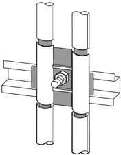
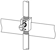
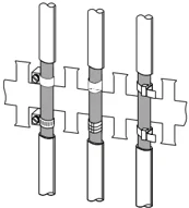
The figure below shows some options for mounting shielded cables, using cable clamps.

See also Terminating shielded cables on the shield connection element (Page 121)
A.2.7 Equipotential bonding
Potential differences Potential differences can occur between separate system elements. This can result in high equipotential currents, e.g. if the cable shielding is terminated at both ends and grounded to different system components.
The cause of potential difference can be differences in the power supplies.
WARNING Cable shielding is not suitable for equipotential bonding. Always use the prescribed cables (for example, with a cross-section of 16 mm²). When installing MPI/DP networks, make sure that you provide a sufficient conductor cross-section. Otherwise, interface hardware might be damaged or even destroyed.
273
Appendix A.2 Protection against electromagnetic interference
Equipotential bonding conductor
To reduce potential differences and ensure proper functioning of your electronic equipment, you must install equipotential bonding conductors.
Note the following points on the use of equipotential bonding conductors:
- The lower the impedance of an equipotential bonding conductor, the more effective is equipotential bonding.
- When shielded signal cables interconnect two system components and the shielding is connected on both ends to ground/protective conductors, the impedance of the additional equipotential bonding conductor must not exceed 10 % of the shielding impedance.
- Determine the cross-section of your equipotential bonding conductor on the basis of the maximum equalizing current that will flow through it. The equipotential bonding conductor cross-section that has proven best in practice is 16 mm².
- Always use equipotential bonding conductors made of copper or galvanized steel. Always connect the cables on a large surface to the equipotential conductor bar/protective conductor and protect it against corrosion.
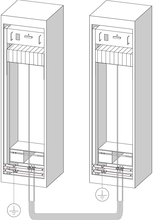
- Route your equipotential bonding conductor to minimize the area between the equipotential bonding conductor and signal lines as far as possible (see the figure below).
274
Appendix A.2 Protection against electromagnetic interference
A.2.8 Cable routing inside buildings
Introduction Inside buildings (inside and outside cabinets), clearances must be maintained between groups of different cables to achieve the necessary electromagnetic compatibility (EMC). The following table contains information on the general rules governing clearances to enable you to choose the correct cables.
How to read the table To find out how to run two cables of different types, proceed as follows:
- Look up the type of the first cable in column 1 (Cables for ...).
- Look up the type of the second cable in the corresponding section in column 2 (and cables for ...).
- Note the applicable directives in column 3 (Run ...).
Table A- 6 Cable routing inside buildings
\begin{tabular}{|p{0.3\textwidth}|p{0.3\textwidth}|p{0.3\textwidth}|} \hline \textbf{Cables for ...} & \textbf{and cables for ...} & \textbf{Run ...} \ \hline \begin{itemize} \item Bus signals, shielded (for example, PROFIBUS, PROFINET) \item Data signals, shielded (programming devices, operator panels, printers, counter inputs, etc.) \item Analog signals, shielded \item DC voltage (≤ 60 V), unshielded \item Process signals (≤ 25 V), shielded \item AC voltage (≤ 5 V), unshielded \item Monitors (coaxial cable) \end{itemize} & \begin{itemize} \item Bus signals, shielded (for example, PROFIBUS, PROFINET) \item Data signals, shielded (programming devices, operator panels, printers, counter inputs, etc.) \item Analog signals, shielded \item DC voltage (≤ 60 V), unshielded \item Process signals (≤ 25 V), shielded \item AC voltage (≤ 25 V), unshielded \item Monitors (coaxial cable) \end{itemize} & In common bundles or cable ducts \ \cline{2-3} & \begin{itemize} \item DC voltage (> 60 V and ≤ 400 V), unshielded \item AC voltage (> 25 V and ≤ 400 V), unshielded \end{itemize} & In separate bundles or cable ducts (no minimum clearance necessary) \ \cline{2-3} & \begin{itemize} \item DC and AC voltage (> 400 V), unshielded \end{itemize} & \textbf{Inside cabinets:}\newline In separate bundles or cable ducts (no minimum clearance necessary)\newline \textbf{Outside cabinets:}\newline On separate cable racks with a clearance of at least 10 cm \ \hline \end{tabular}
275