Maintenance
9.1 Overview
Maintenance in terms of the S7-300
- refers to the backup of the operating system to a SIMATIC Micro Memory Card
- Updating of the operating system from a SIMATIC Micro Memory Card
- Updating of the firmware online
- Backing up of project data on a SIMATIC Micro Memory Card
- Replacement of modules
- Replacement of fuses in digital output modules
9.2 Backing up firmware on a SIMATIC Micro Memory Card
Situations which require backup of the firmware
It is advisable in certain situation to backup your CPU firmware:
You may want to replace the CPU in your system with a CPU out of storage. In this case you should make sure that the firmware of the shelf CPU and of the system firmware are identical.
It is also advisable to create an emergency backup copy of the firmware.
On which CPUs can you back up the firmware?
Backup of the firmware is possible as of the following CPU versions:
| CPU | Order number | Firmware as of | Required Micro Memory Card ≥ in MByte |
|---|---|---|---|
| 312 | as of 6ES7312-1AD10-0AB0 | V2.0.0 | 2 |
| as of 6ES7312-1AE13-0AB0 | V2.0.12 | ||
| as of 6ES7312-1AE14-0AB0 | V3.0 | ||
| 312C | as of 6ES7312-5BD00-0AB0 | V1.0.0 | 2 |
| as of 6ES7312-5BE03-0AB0 | V2.0.12 | ||
| as of 6ES7312-5BF04-0AB0 | V3.3.1 | ||
| 313C | as of 6ES7313-5BE00-0AB0 | V1.0.0 | 2 |
| as of 6ES7313-5BF03-0AB0 | V2.0.12 | ||
| as of 6ES7313-5BG04-0AB0 | V3.3.1 |
189
Maintenance
9.2 Backing up firmware on a SIMATIC Micro Memory Card
| CPU | Order number | Firmware as of | Required Micro Memory Card ≥ in MByte |
|---|---|---|---|
| 313C-2 PtP | as of 6ES7313-6BE00-0AB0 | V1.0.0 | 2 |
| as of 6ES7313-6BF03-0AB0 | V2.0.12 | ||
| as of 6ES7313-6BG04-0AB0 | V3.3.1 | ||
| 313C-2 DP | as of 6ES7313-6CE00-0AB0 | V1.0.0 | 4 |
| as of 6ES7313-6CF03-0AB0 | V2.0.12 | ||
| as of 6ES7313-6CG04-0AB0 | V3.3.1 | ||
| 314 | as of 6ES7314-1AF10-0AB0 | V2.0.0 | 2 |
| as of 6ES7314-1AG13-0AB0 | V2.0.12 | ||
| as of 6ES7314-1AG14-0AB0 | V3.0 | ||
| 314C-2 PtP | as of 6ES7314-6BF00-0AB0 | V1.0.0 | 2 |
| as of 6ES7314-6BG03-0AB0 | V2.0.12 | ||
| as of 6ES7314-6BH04-0AB0 | V3.3.1 | ||
| 314C-2 DP | as of 6ES7314-6CF00-0AB0 | V1.0.0 | 4 |
| as of 6ES7314-6CG03-0AB0 | V2.0.12 | ||
| as of 6ES7314-6CH04-0AB0 | V3.3.1 | ||
| 314C-2 PN/DP | as of 6ES7314-6EH04-0AB0 | V3.3 | 8 |
| 315-2 DP | as of 6ES7315-2AG10-0AB0 | V2.0.0 | 4 |
| as of 6ES7315-2AH14-0AB0 | V3.0 | ||
| 315-2 PN/DP | as of 6ES7315-2EG10-0AB0 | V2.3.0 | 4 |
| as of 6ES7315-2EH14-0AB0 | V3.1 | 8 | |
| 317-2 DP | as of 6ES7317-2AJ10-0AB0 | V2.1.0 | 4 |
| as of 6ES7317-2AK14-0AB0 | V3.3.1 | ||
| 317-2 PN/DP | as of 6ES7317-2EJ10-0AB0 | V2.2.0 | 4 |
| as of 6ES7317-2EK14-0AB0 | V3.1 | 8 | |
| 319-3 PN/DP | as of 6ES7318-3EL00-0AB0 | V2.4.0 | 8 |
| as of 6ES7318-3EL01-0AB0 | V3.2 | 8 |
190
This is how you back up the firmware of your CPU to the SIMATIC Micro Memory Card
Table 9-1 Backing up the firmware to the SIMATIC Micro Memory Card
| Step | Action required: | This happens in the CPU: |
|---|---|---|
| 1 | Insert the new SIMATIC Micro Memory Card into the CPU. | The CPU requests a memory reset. |
| 2 | Keep the mode selector in the MRES position. | - |
| 3 | POWER OFF/POWER ON and keep the mode selector in the MRES position until ... | ... the STOP, RUN and FRCE LEDs start flashing. |
| 4 | Mode selector in STOP position. | - |
| 5 | Switch mode selector briefly to MRES position, then let it return to STOP. | • The CPU starts to back up the operating system on the SIMATIC Micro Memory Card.• All LEDs are lit during the backup operation.• The STOP LED flashes when the backup is complete to indicate that the CPU requires a memory reset. |
| 6 | Remove the SIMATIC Micro Memory Card. | - |
9.3 Updating the firmware
Note
Communication shutdown during firmware updates on PROFINET CPUs with integrated switch
Note that the PROFINET interface and the integrated switch are shut down when you update the firmware on this CPU.
During the firmware update on a CPU operated in a line structure, communication via the CPU's integrated switch to downstream devices is shut down.
191
Maintenance
9.3 Updating the firmware
9.3.1 Firmware update using a Micro Memory Card
In which situations should I update the firmware?
After (compatible) function expansions, or after an enhancement of operating system performance, the firmware of the CPU should be upgraded (updated) to the latest version.
Where do I get the latest version of the firmware?
You can obtain the latest Firmware is available as *.UPD files from your Siemens contact partner, or download it from the Internet at the Siemens Homepage (http://www.siemens.com/automation/service&support)
Firmware update using a SIMATIC Micro Memory Card
Table 9-2 Firmware update using a SIMATIC Micro Memory Card
| Step | Action required: | This happens in the CPU: |
|---|---|---|
| 1 | RecommendationBefore you update the CPU firmware, create a backup copy of the "old" firmware on an empty SIMATIC Micro Memory Card. If problems occur during the update, you can reload your old firmware from the SIMATIC Micro Memory Card. | |
| 2 | Transfer the update files to a blank SIMATIC Micro Memory Card using STEP 7 and your programming device. | - |
| 3 | Switch off CPU power and insert a SIMATIC Micro Memory Card containing the firmware update. | - |
| 4 | Switch on power. | • The CPU automatically detects the SIMATIC Micro Memory Card with the firmware update and runs the update.• All LEDs are lit during firmware update.• The STOP LED flashes when the FW update is completed, and indicates that the CPU requires a memory reset. |
| 5 | Switch off CPU power and remove a SIMATIC Micro Memory Card containing the firmware update. | - |
192
Maintenance 9.3 Updating the firmware
Result
You updated the CPU with a new firmware version.
The address and baud rate of the first interface remain retentive. All other parameters were reset during the firmware update.
NOTICE Any cancellation of the firmware update caused by actions such as POWER OFF/ON or removal of the Micro Memory Card can lead to the loss of the CPU firmware. In this mode, only the SF-LED flashes at a frequency of 2 Hz, while all other LEDs are switched off. However, since the boot block is retained, you can restore the valid firmware by repeating the FW update as described above.
9.3.2 Updating the firmware online (via networks)
On which CPUs can you update the firmware online?
You can carry out a firmware update online for all CPUs as of V 2.2 and higher.
Information about the firmware update online using MPI or DP networks for older modules is available on the Service&Support pages (http://www.siemens.com/automation/service).
Requirements
- An online firmware update is possible in STEP 7 V 5.3 or higher.
- To update the firmware, you require the *.UPD files which contain the current firmware version.
- The files (*.UPD) containing the current firmware version must be available in the file system on your PG/PC. A folder may contain only the files of one firmware version.
- The CPU can be accessed online.
193
Maintenance 9.3 Updating the firmware
Performing a firmware update
- Run STEP 7 and change to HW Config.
- Open the station containing the CPU you want to update.
- Select the CPU.
- Select the menu command PLC > Update Firmware. The menu command can only be executed if the selected CPU supports the "Update Firmware" function.
- The Update firmware dialog box opens. Click Browse to select the path to the firmware update files (*.UPD)
- After you selected a file, the information in the lower fields of the Update Firmware dialog box shows you the firmware file and version for the corresponding modules.
- Click the Run button. STEP 7 verifies that the selected file can be interpreted by the module, and then downloads the file to the CPU. If this requires changing the operating state of the CPU, you will be asked to perform these tasks in the relevant dialog boxes. The CPU then automatically updates the firmware.
- In STEP 7 (reading the CPU diagnostics buffer), verify that the CPU can start with the new firmware.
Result
You have updated the CPU online with a new firmware version.
The address and baud rate of the first interface remain retentive. All other parameters were reset during the firmware update.
194
Maintenance 9.4 Backup of project data to a Micro Memory Card
9.4 Backup of project data to a Micro Memory Card
Function principles
Using the Save project to Micro Memory Card and Retrieve project from Micro Memory Card functions, you can save all project data to a SIMATIC Micro Memory Card, and retrieve these at a later time. The SIMATIC Micro Memory Card can be located in a CPU or in the Micro Memory Card programming adapter of a PG or PC.
Project data is compressed before it is saved to a SIMATIC Micro Memory Card, and uncompressed on retrieval.
Note
In addition to project data, you may also have to save your user data to the SIMATIC MMC. Always select a SIMATIC Micro Memory Card with sufficient memory capacity.
A message warns you of insufficient memory capacity on your SIMATIC Micro Memory Card.
The volume of project data to be saved corresponds with the size of the project's archive file.
Note
For technical reasons, you can only transfer the entire contents (user program and project data) using the Save project to Micro Memory Card action.
195
Maintenance
9.4 Backup of project data to a Micro Memory Card
Handling the functions
How you use the Save project to memory card / Retrieve project from memory card functions depends on the location of the SIMATIC micro memory card:
-
When the SIMATIC MMC is inserted in the MMC slot, select a project level (for example, CPU, programs, sources or blocks) which is uniquely assigned to the CPU from the project window in SIMATIC Manager. Select the PLC > Save project to Memory Card or PLC > Retrieve project from Memory Card menu command. The program now writes all configuration data to the SIMATIC Micro Memory Card, or retrieves these data from the card.
-
If project data are not available on the currently used programming device (PG/PC), you can select the source CPU from the "Accessible nodes" window. Select PLC > Display accessible nodes command to open the "Accessible nodes" window. Select the connection/CPU that contains your project data on SIMATIC Micro Memory Card. Now select menu command Retrieve project from Memory Card.
-
If the SIMATIC MMC is located in the MMC programming unit of a PG or PC, open the "S7 memory card window" using the File > S7 Memory Card > Open command. Select the PLC > Save project to Memory Card or PLC > Retrieve project from Memory Card menu command. to open a dialog in which you can select the source or target project.
Note
Project data can generate high data traffic. Especially in RUN mode with read/write access to the CPU, this can lead to waiting periods of several minutes.
Sample application
When you assign more than one member of your service and maintenance department to perform maintenance tasks on a SIMATIC PLC, it may prove difficult to provide quick access to current configuration data to each staff member.
However, CPU configuration data available locally on any CPU that is to be serviced can be accessed by any member of the service department. They can edit these data and then release the updated version to all other personnel.
196
Maintenance 9.5 Resetting to the Delivery State
9.5 Resetting to the Delivery State
Delivery state of the CPU
Default values set at the CPU properties:
Table 9-3 Properties of the CPU in the delivery state
Procedure
Proceed as follows in order to reset a CPU to the delivery state via the mode selector switch:
- Switch off the supply voltage.
- Remove the SIMATIC Micro Memory Card from the CPU.
- Hold the mode selector switch in the MRES setting and switch the supply voltage on again.
- Wait until LED lamp image 1 from the subsequent overview is displayed.
- Release the mode selector switch, set it back to MRES within 3 seconds and hold it in this position.
- Wait until LED lamp image 2 from the next overview is displayed. This lamp image lights up for approximately five seconds, that is for the duration of RESET. During this period you can abort the resetting procedure by releasing the mode selector switch.
- Wait until LED lamp image 3 from the subsequent overview is displayed and release the mode selector switch again.
The CPU is now reset to the delivery state. It starts without buffering (all LEDs are lit) and changes to the STOP mode.
197
Maintenance
9.6 Module installation/removal
Lamp images while the CPU is being reset
While you are resetting the CPU to the delivery state, the LEDs light up consecutively in the following lamp images:
Table 9-4 Lamp images
Note
When removing a PROFINET CPU for use at a different location, or when putting it on shelf, always restore the CPU to factory settings since its IP address and device name are usually stored in retentive memory.
\subsection*{9.6 Module installation/removal}
Installation and wiring rules
The table below shows you points to follow when wiring, installing or removing S7-300 modules.
Maintenance 9.6 Module installation/removal
Initial situation
The module you want to replace is still mounted and wired. You want to install the same type of module.
WARNING Disturbances can corrupt data if you insert or remove S7-300 modules while data are being transferred via the integrated interface of your CPU. You should never replace any modules of the S7-300 while data traffic is active at an integrated interface. If you are not certain whether or not data transfer is active on the interface, unplug the connector at the interface before you replace the module.
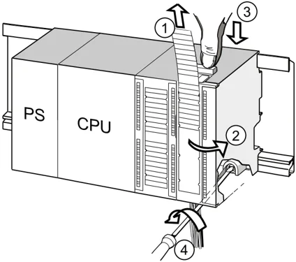
Removing the module (SM/FM/CP)
To remove the module:

Number Description ① Remove labeling strips. ② Open module. ③ Press unlocking mechanism/loosen mounting screw and pull out front connector. ④ Remove mounting screw of module and swing module out.
199
Maintenance 9.6 Module installation/removal
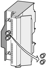
Removing the front connector coding from the module
Remove the top part of the front connector coding from the new module to be installed. Reason: This part is already inserted in the wired front connector.
Installing a new module
To install the new module:
- Hang in a new module of same type.
- Swivel the module down into place.
- Screw-tighten the module.
- Slide the labeling strips into the module.
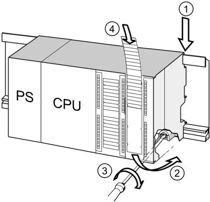
Number Description ① Hang module onto rail ② Swivel module downward ③ Screw-tighten the module ④ Insert labeling strips
200
Maintenance 9.6 Module installation/removal
Removing the front connector coding from the front connector
To rewire a "used" front connector for a different module, remove the front connector coding from the front connector:
Simply push the front connector coding out of the front connector using a screwdriver.
Reinsert the top part of the front connector coding into the front connector coding of the old module.
Putting a new module into service
Proceed as follows to put the new module into service:
- Open the front door.
- Reinstall the front connector.
- Close the front panel.
- Switch the load voltage back on.
- Reset the CPU to RUN mode.
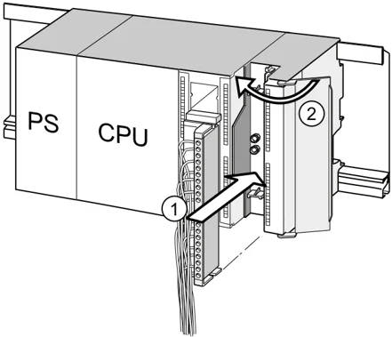
Number Description ① Move the front connector into operating position ② Close front panel
Reaction of the S7-300 after module replacement
After a module replacement, the CPU switches to run mode, provided no error has occurred. If the CPU stays in STOP mode, you can view the cause of error in STEP 7 (see the Programming with STEP 7 user manual).
201
Maintenance 9.7 Digital output module: Changing fuses
9.7 Digital output module: Changing fuses
Fuses for digital outputs The digital outputs of the following digital output modules are short-circuit protected by fusing of the channel groups:
- Digital output module SM 322; DO 16 x AC 120 V
- Digital output module SM 322; DO 8 x AC 120/230 V
System check Eliminate the causes of fuse tripping.
Replacement fuses If replacement is required, you can use the following fuses:
- 8 A, 250 V fuse – Wickmann 19 194-8 A – Schurter SP001.013 – Littlefuse 217.008
- Fuse holder – Wickmann 19 653
WARNING Injuries or damages can result from improper handling of the digital modules. There are dangerous voltages > 25 VAC or > 60 VDC beneath the covers to the right of the module. Before you open these covers, make sure that you have either unplugged the front connector from the module or isolated the module from power.
WARNING Injuries or damages can result from improper handling of front connectors. Dangerous voltages > 25 VAC or > 60 VDC may be present at the pins when you pull or insert the front connector during operation. If such voltages are present at the front connector, only qualified electricians or personnel instructed by such specialists may replace live modules, in such a way that they avoid touching the module pins in the process.
202


Maintenance 9.7 Digital output module: Changing fuses
Location of the fuses on the digital output module
Digital output modules are equipped with 1 fuse per channel group. The fuses are located at the left side of the digital output module. The following figure shows you where to find the fuses on the digital output modules.
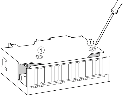
Replacing fuses
The fuses are located at the left side of the module. Replace the fuses as follows:
- Switch the CPU to STOP.
- Switch off the load voltage of the digital output module.
- Remove the front connector from the digital output module.
- Loosen the fixing screw of the digital output module.
- Swing out the digital output module.
- Remove the fuse holder from the digital output module ①.
- Replace the fuse.
- Screw the fuse holder back into the digital output module.
- Reinstall the digital output module.
203
Maintenance 9.7 Digital output module: Changing fuses
204
Debugging functions, diagnostics and troubleshooting 10
10.1 Overview
This chapter helps you to get acquainted with tools you can use to carry out the following tasks:
- Hardware/software error diagnostics.
- Elimination of hardware/software errors.
- Testing the hardware/software – for example, during commissioning.
Note
It would go beyond the scope of this manual to provide detailed descriptions of all the tools you can use for diagnostics, testing and troubleshooting functions. Additional notes are found in the relevant hardware/software manuals.
10.2 Reading out service data
Application (for CPUs ≥ V2.8)
In the case of a service, for example if the CPU signals the state "DEFECTIVE" (all LEDs blinking), you have the option of saving special information for analyzing the CPU state.
This information is stored in the diagnostic buffer and in the actual service data.
Select the "Target system -> Save service data" command to read and this information and save the data to a file to forward to Customer Support.
Procedure
-
If the CPU is in the state "DEFECTIVE" (all LEDs blinking), switch the power supply off and on (power off/on).
Result: The CPU is now in STOP mode.
-
As soon as the CPU goes to "STOP" mode, select the corresponding CPU with the menu command in the SIMATIC Manager: Target system > Available nodes".
-
Use the SIMATIC Manager menu command "Target system > Save service data" to save the service data.
Result: A dialog box opens in which you specify the storage location and name of the two files.
-
Save the file.
-
Forward these files to Customer Support on request.
205

Debugging functions, diagnostics and troubleshooting 10.3 Identification and maintenance data of the CPU
10.3 Identification and maintenance data of the CPU
Definition and properties
Identification and maintenance data (I&M) is information that is stored in a module for the purpose of providing you with support when:
- checking the system configuration
- locating modified plant hardware
- troubleshooting a plant
Identification data (I data) is information about the module (some of which may be printed on the module housing) such as the order and serial number. I data is manufacturer's information about the module. It is fixed and can only be read.
Maintenance data (M data) represent system-specific information such as the installation location. M data is created during configuration and written to the module.
I&M data can be used to identify modules uniquely on the network.
Reading and writing I&M data with STEP 7
Read
- STEP 7 returns I&M data in "Module status" ("General" and Identification" tab) and in "Accessible nodes" (detail view). See the STEP 7 Online Help.
- You can read I&M data by calling SFC51 in the user program. Declare the SSL parts list number and index at the input parameters of SFC51 (see the table below).
- CPUs which support reading of I&M data on the "Start page" and "Identification" page using the web server: