Configuring
4.9 Electrical assembly, protective measures and grounding
Example: Assembly with CPU 31xC and isolated modules
The figure below shows an example of such a configuration: A CPU 31xC with isolated modules. The CPU 31xC (1) is automatically grounded.
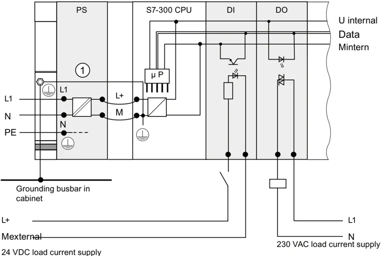
Grounding busbar in cabinet
L+ Mexternal 24 VDC load current supply
U internal Data Mintern
L1 N 230 VAC load current supply
Common potential modules
In a configuration containing modules with common potential, the reference potentials of the control circuit (Minternal) and analog circuit (Manalog) are not galvanically isolated.
47
Configuring
4.9 Electrical assembly, protective measures and grounding
Example: Installing an S7-300 with common potential modules
When using an SM 334 AI 4/AO 2 analog input/output module, connect one of the grounding terminals Manalog to the CPU chassis ground.
The figure below shows an example of such a configuration: An S7-300 with common potential modules
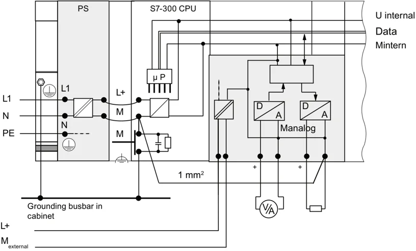
48
Configuring 4.9 Electrical assembly, protective measures and grounding
4.9.5 Grounding measures
Bonding to ground
Low-impedance connections to ground reduce the risk of electric shock as a result of a short-circuit or system fault. Low-impedance connections (large surface, large-surface contact) reduce the effects of interference on the system or the emission of interference signals. An effective shielding of cables and devices is also a significant contribution.
WARNING
All protection class 1 devices, and all larger metal parts, must be bonded to protective ground. That is the only way to safely protect operators from electrical shock. This also discharges any interference transmitted from external power supply cables, signal cables or cables to the I/O devices.
Measures for protective grounding
The table below shows an overview of the most important measures for protective grounding.
Table 4- 8 Measures for protective grounding
\begin{tabular}{|l|l|} \hline \textbf{Device} & \textbf{Measures} \ \hline Cabinet / mounting frame & Connection to a central grounding point (grounding busbar, for example) using cables with protective conductor quality. \ \hline Rack/ mounting rail & Connection to a central grounding point via cable with minimum cross-section of 10 mm$^2$ if the mounting rails are not installed in the cabinet and not interconnected with larger metal parts. \ \hline Module & None \ \hline I/O Device & Grounding via grounding-type plug \ \hline Sensors and final control elements & Grounding in accordance with regulations applying to the system \ \hline \end{tabular}
49

Configuring 4.9 Electrical assembly, protective measures and grounding
Rule: Connect the cable shielding to ground
You should always connect both ends of the cable shielding to ground / system ground. This is the only way to achieve an effective interference suppression in the higher frequency range.
Attenuation is restricted to the lower frequency range if you connect only one end of the shielding (that is, at the start or end of the cable) to ground. One-sided shielding connections could be more favorable in situations
- not allowing the installation of an equipotential bonding conductor,
- where analog signals (some mA or µA) are transferred,
- or if foil shielding is used (static shielding).
Note
Whenever potential differences develop between two grounding points, an equalizing current can develop on a shielding that is connected on both ends. Compensate for this situation by installing an additional equipotential cable.
CAUTION
Always avoid the flow of operating current to ground.
Rule: Grounding the load circuits
You should always ground the load circuits. This common reference potential (ground) ensures proper functioning.
Note
(not valid for CPU 31xC)
If you want to locate a ground fault, provide your load power supply (terminal L- or M) or the isolating transformer with a removable connection to the protective conductor (see Overview: Grounding Number 4).
50

Configuring
4.9 Electrical assembly, protective measures and grounding
Connecting the load voltage reference potential
A complex system containing many output modules requires an additional load voltage for switching the final control elements.
The table below shows how to connect the load voltage reference potential Mexternal for the various configurations.
Table 4- 9 Connecting the load voltage reference potential \begin{tabular}{|l|l|l|l|} \hline Installation & common potential modules & isolated modules & Comment \ \hline grounded & Connect Mexternal with M on the CPU & Connect or do not connect Mexternal to the grounding busbar & - \ \hline ungrounded & Connect Mexternal with M on the CPU & Connect or do not connect Mexternal to the grounding busbar & Ungrounded installation with CPU 31xC is not possible \ \hline \end{tabular}
Operating Instructions, 03/2011, A5E00105492-12 \hfill 51
Configuring 4.9 Electrical assembly, protective measures and grounding
4.9.6 Overview: Grounding
CPU 31xC
The figure below shows you the complete assembly of an S7-300 with CPU 31xC with a power supply from TN-S mains. The PS 307 supplies the CPU and the load current circuit of the 24 VDC modules. Remark: The layout of the power connections does not correspond with their physical arrangement; it was merely selected to give you a clear overview.
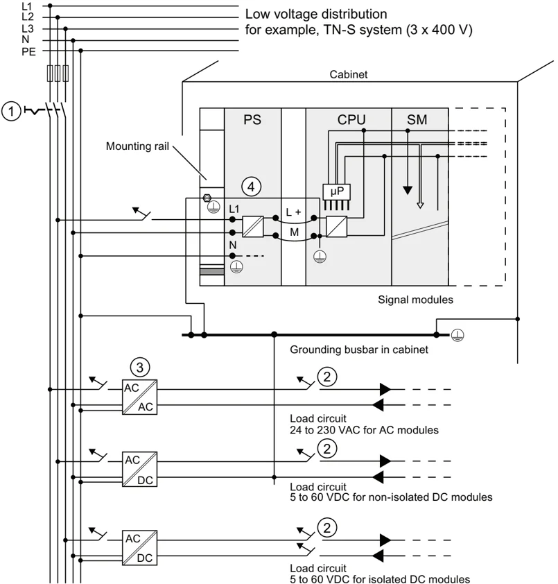
Number Description ① Master switch ② Short-circuit and overload protection ③ Load current supply (galvanic isolation) ④ This connection is made automatically for the CPU 31xC.
Figure 4-1 Connecting the load voltage reference potential
52
Configuring
4.9 Electrical assembly, protective measures and grounding
All CPUs except CPU 31xC
The figure below shows you the complete assembly of an S7-300 with TN-S mains supply (does not apply to CPU 31xC). The PS 307 supplies the CPU and the load current circuit of the 24 VDC modules.
Remark: The layout of the power connections does not correspond with their physical arrangement; it was merely selected to give you a clear overview.
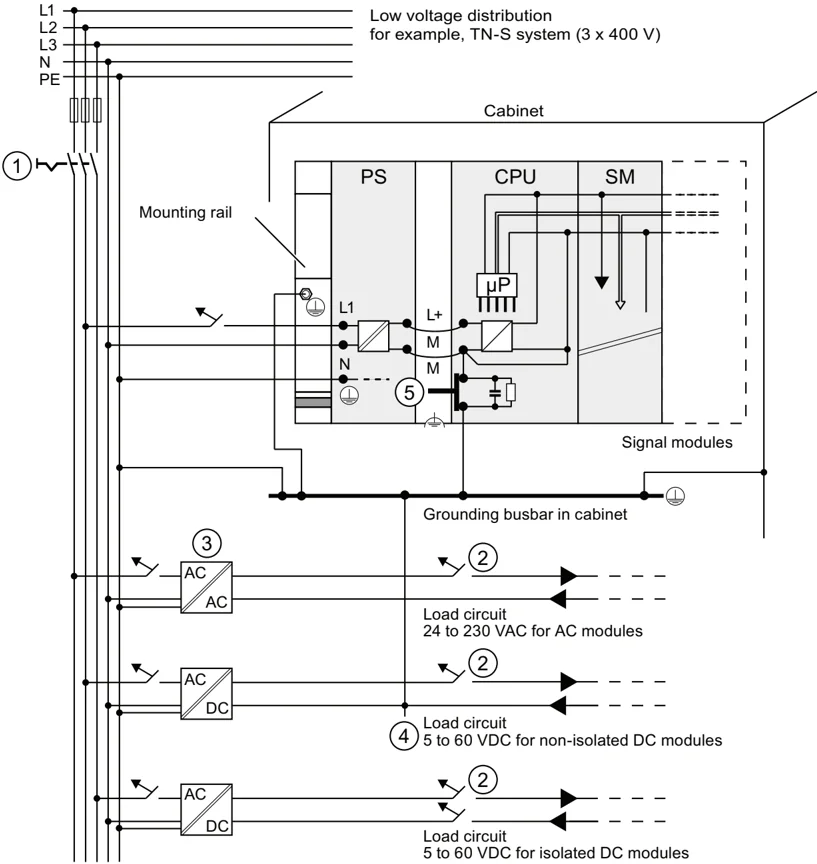
Number Description ① Master switch ② Short-circuit and overload protection ③ The load current supply (galvanic isolation) ④ Removable connection to the grounding conductor, for ground fault localization ⑤ Grounding slide contact of the CPU (not CPU 31xC)
Figure 4-2 Connecting the load voltage reference potential
53
Configuring 4.10 Selection of the load power supply
4.10 Selection of the load power supply
Task of the load power supply
The load power supply feeds the input and output circuits (load circuits), and the sensors and actuators.
Features of load power supply units
You will have to adapt the load power supply unit to your specific application. The table below shows a comparison of the various load power supply units and their features to help you make your choice:
Table 4- 10 Features of load power supply units
Load power supply requirements
Only an extra-low voltage of ≤ 60 VDC which is safely isolated from mains may be used as load voltage. Safe isolation can be achieved in accordance with the requirements in, for example, VDE 0100 Part 410/HD 384-4-41/IEC 364-4-41 (as functional extra-low voltage with safe isolation) or VDE 0805/EN 60950/IEC 950 (as safety extra-low voltage SELV) or VDE 0106 Part 101.
Load current determination
The required load current is determined by the accumulated load current of all sensors and actuators connected to the outputs.
A short-circuit induces a surge current at the DC outputs which is 2 to 3 times higher than the rated output current, until the clocked electronic short-circuit protection comes into effect. Make allowances for this increased short-circuit current when selecting your load power supply unit. Uncontrolled load power supplies usually provide this excess current. With controlled load power supplies, and particularly for low output power up to 20 A, always ensure that the supply can handle this excess current.
54
Configuring 4.10 Selection of the load power supply
Example: S7-300 with load power supply from PS 307
The figure below shows the overall S7-300 configuration (load power supply unit and grounding concept), with TN-S mains supply. The PS 307 supplies the CPU and the load current circuit of the 24 VDC modules.
Note
The layout of the power connections does not correspond with their physical arrangement; it was merely selected to give you a clear overview.
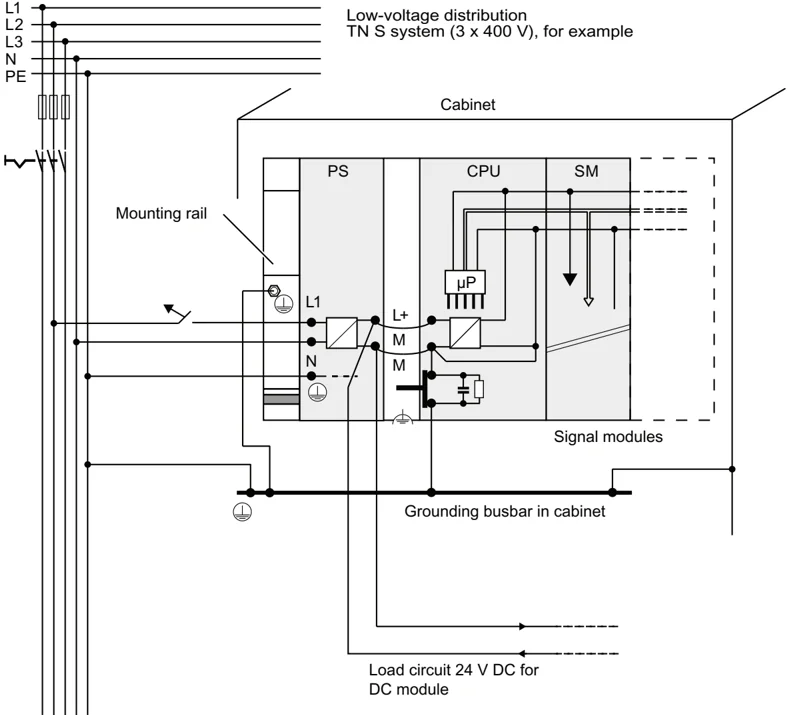
Example: S7-300 with load power supply from PS 307
55
Configuring 4.11 Planning subnets
4.11 Planning subnets
4.11.1 Overview
Subnets Subnets available in SIMATIC for the various automation levels (process, cell, field and actuator/sensor level ):
- Multi-Point Interface (MPI)
- PROFIBUS
- PROFINET (Industrial Ethernet)
- Point-to-point communication (PtP)
- Actuator/Sensor Interface (ASI)
Multi-Point Interface (MPI) Availability: For all CPUs described in this document. MPI is a small area subnet containing a small number of nodes at the field/cell level. It is a multipoint-capable interface in SIMATIC S7/M7 and C7. designed as PG interface, for networking a small number of CPUs, or for low volume data exchange with PGs. MPI always retains the last configuration of the transmission rate, node number and highest MPI address, even after CPU memory reset, power failure or deletion of the CPU parameter configuration. It is advisable to use the PROFIBUS DP network components for your MPI network configuration. The same configuration rules apply. Exception: OWG modules are not allowed in the MPI network.
PROFIBUS Availability: CPUs with the "DP" name suffix are equipped with a PROFIBUS interface (CPU 315-2 DP, for example). PROFIBUS represents the network at the cell and field level in the SIMATIC open, multivendor communication system. PROFIBUS is available in two versions:
- PROFIBUS DP field bus for high-speed cyclic data exchange, and PROFIBUS-PA for intrinsically safe applications (requires DP/PA coupler).
- The cell level as PROFIBUS (FDL or PROFIBUS FMS) for high-speed data exchange with communication partners at the same authorization level (can only be implemented via CP).
56
Configuring 4.11 Planning subnets
PROFINET (Industrial Ethernet)
Availability: CPUs with the "PN" name suffix are equipped with a PROFINET interface (CPU 317-2 PN/DP or CPU 319-3 PN/DP for example). A PROFINET interface, or communication processors, can be used to implement Industrial Ethernet in an S7-300 CPU system.
Industrial Ethernet, in an open multivendor communication system, represents the SIMATIC network at the process and cell level. PROFINET CPUs, however, also support real-time communication at the field level. This structure also supports S7 communication. Industrial Ethernet is suitable for high-speed and high-volume data exchange, and for remote network operations via gateway.
PROFINET is available in two versions:
- PROFINET IO and
- PROFINET CBA.
PROFINET IO is a communication concept for the implementation of modular, distributed applications. PROFINET IO allows you to create automation solutions you are familiar with from PROFIBUS.
PROFINET CBA (Component based automation) is an automation concept for the implementation of applications with distributed intelligence. PROFINET CBA lets you create distributed automation solutions, based on default components and partial solutions. This concept satisfies demands for a higher degree of modularity in the field of mechanical and systems engineering by extensive distribution of intelligent processes.
Component based automation allows you to use complete technological modules as standardized components in large systems.
Point-to-point communication (PtP)
Availability: CPUs with "PtP" name suffix are equipped with a second interface, namely the PtP interface (CPU 314C-2 PtP, for example)
PtP does not represent a subnet in the common sense, because it is used to interconnect only two stations.
If a PtP interface is not available, you require PtP Communication Processors (CP).
Actuator/Sensor Interface (ASI)
Implementation by means of communication processors (CP).
The ASI, or actuator/sensor interface, represents a subnet system on the lowest process level for automation systems. It is designed especially for networking digital sensors and actuators. The maximum data volume is 4 bit per slave station.
S7-300 CPUs require communication processor for the ASI connection.
Reference
For additional information on communication, refer to the Communication with SIMATIC manual.
57
Configuring 4.11 Planning subnets
4.11.2 Configuring MPI and PROFIBUS subnets
4.11.2.1 Overview
The next section contains all the information you require to configure MPI, PtP and PROFIBUS subnets:
Contents
- MPI, PtP and PROFIBUS subnets
- Multi-Point Interface
- PROFIBUS DP
- MPI and PROFIBUS network components
- Example of networks - MPI
4.11.2.2 Basic information relating to MPI and PROFIBUS subnets
Convention: device = node All devices you interconnect on the MPI or PROFIBUS network are referred to as nodes.
Segment A segment is a bus line between two terminating resistors. A segment may contain up to 32 nodes. It is also limited with respect to the permitted line length, which is determined by the transmission rate.
Baud rate Maximum transmission rates:
- MPI:
- CPU 314C-2 PN/DP, CPU 315-2 PN/DP, CPU 317 and CPU 319-3 PN/DP: 12 Mbit/s
- All other CPUs: 187,5 kbit/s
- PROFIBUS DP: 12 Mbit/s
58
Configuring 4.11 Planning subnets
Number of nodes
Maximum number of nodes per subnet.
Table 4- 11 Subnet nodes \begin{tabular}{|l|l|l|} \hline Parameters & MPI & PROFIBUS DP \ \hline Number & 127 & 126 $^1$ \ \hline Addresses & 0 to 126 & 0 to 125 \ \hline Comment & Default: 32 addresses & of those: \ & Reserved addresses: & \bullet 1 master (reserved) \ & \bullet Address 0 for PG & \bullet 1 PG connection (address 0 reserved) \ & \bullet Address 1 for OP & \bullet 124 slaves or other masters \ \hline \end{tabular}
$^1$ Note the CPU-specific maximum specifications in the relevant CPU manual.
MPI/PROFIBUS DP addresses
You need to assign an address to all nodes in order to enable intercommunication:
- On the MPI network: an "MPI address"
- On the PROFIBUS DP network: "a PROFIBUS DP address"
You can use the PG to set the MPI/PROFIBUS addresses for each one of the nodes (some of the PROFIBUS DP slaves are equipped with a selector switch for this purpose).
Default MPI/PROFIBUS DP addresses
The table below shows you the default setting of the MPI/PROFIBUS DP addresses, and the factory setting of the highest MPI/PROFIBUS DP addresses for the nodes.
Table 4- 12 MPI/PROFIBUS DP addresses \begin{tabular}{|l|l|l|l|} \hline Node & Default MPI/ & Default highest MPI & Default highest PROFIBUS \ (device) & PROFIBUS DP address & address & DP address \ \hline PG & 0 & 32 & 126 \ \hline OP & 1 & 32 & 126 \ \hline CPU & 2 & 32 & 126 \ \hline \end{tabular}
Rules: Assignment of MPI/PROFIBUS DP addresses
Note the following rules before assigning MPI/PROFIBUS addresses:
- All MPI/PROFIBUS subnet addresses must be unique.
- The highest MPI/PROFIBUS address must be greater than or equal to the actual MPI/ PROFIBUS address and must be identical for each node. (Exception: connecting a PG to multiple nodes; refer to the next chapter).
59
Configuring
4.11 Planning subnets
Differences in the MPI addresses of CPs/FMs in an S7300 system
Table 4- 13 MPI addresses of CPs/FMs in an S7-300 system
Recommendation for MPI addresses
Reserve MPI address "0" for a service PG, or "1" for a service OP, for temporary connections of these devices to the subnet. You should therefore assign different MPI addresses to PGs/OPs operating on the MPI subnet.
Recommended MPI address of the CPU for replacement or service operations:
Reserve MPI address "2" for the CPU. This prevents duplication of MPI addresses after you connect a CPU with default settings to the MPI subnet (for example, when replacing a CPU). You should assign an MPI address greater than "2" to CPUs in the MPI subnet.
Recommendation for PROFIBUS addresses
Reserve PROFIBUS address "0" for a service PG that you can subsequently connect briefly to the PROFIBUS subnet as required. You should therefore assign unique PROFIBUS addresses to PGs integrated in the PROFIBUS subnet.
PROFIBUS DP: Electrical cables or fiber-optic cables?
Use fiber optic cables on a field bus with greater length, rather than copper conductors, in order to be independent on the transmission rate, and to exclude external interference.
Configuring 4.11 Planning subnets
Equipotential bonding For information on what to take into account with respect to equipotential bonding in your network configuration, refer to the corresponding chapter in the appendix.
Reference For more information, refer to the Communication section in CPU 31xC and CPU 31x manual, technical data.
4.11.2.3 Multi-Point Interface (MPI)
Availability All the CPUs described here are equipped with an MPI interface A CPU equipped with an MPI/DP interface is configured and supplied as MPI interface.
Properties The MPI (Multi-Point Interface) represents the CPU interface for PG/OP connections, or for communication on an MPI subnet.
The default baud rate of all CPUs is 187.5 kbps. You can also set 19.2 kbps for communication with an S7-200. Baud rates up to max. 12 Mbps are possible with the CPU 314C-2 PN/DP, CPU 315-2 PN/DP, CPU 317-2 and with the CPU 319-3 PN/DP.
The CPU automatically broadcasts its bus configuration via the MPI interface (the transmission rate, for example). A PG, for example, can thus receive the correct parameters and automatically connect to a MPI subnet.
Devices capable of MPI communication
- PG/PC
- OP/TP
- S7-300 / S7-400 with MPI interface
- S7-200 (only at 19.2 kbps)
NOTICE You may only connect PGs to an MPI subnet which is in RUN. Do not connect other stations (for example, OP, TP) to the MPI subnet while the system is running. Otherwise, transferred data might be corrupted as a result of interference, or global data packages may be lost.
61
Configuring 4.11 Planning subnets
Clock synchronization
The CPU's MPI interface supports clock synchronization. Detailed information is available in the Manual CPU 31x and CPU 31x, Technical specifications, section Clock synchronization.
4.11.2.4 PROFIBUS DP interface
Availability
CPUs with the "DP" have at least one DP interface.
The CPU 314C-2 PN/DP, CPU 315-2 PN/DP and the CPU 317-2 PN/DP feature one MPI/DP interface. The 317-2 DP and 319-3 PN/DP CPUs feature an MPI/DP interface plus an additional DP interface. The factory setting of the CPU's MPI/DP interface is MPI mode. You need to set DP mode in STEP 7 if you want to use the DP interface.
Operating modes for CPUs with two DP interfaces
Table 4- 14 Operating modes for CPUs with two DP interfaces
\begin{tabular}{ll} \hline MPI/DP interface & PROFIBUS DP interface \ \hline \bullet MPI & \bullet not configured \ \bullet DP master & \bullet DP master \ \bullet DP slave $^1$ & \bullet DP slave $^1$ \ \hline \end{tabular}
$^1$ simultaneous operation of the DP slave on both interfaces is excluded
Properties
The PROFIBUS DP interface is mainly used to connect distributed I/O. PROFIBUS DP allows you to create large subnets, for example.
The PROFIBUS DP interface can be configured for operation in master or slave mode, and supports transmission rates up to 12 Mbps
The CPU broadcasts its bus parameters (transmission rate, for example) via the PROFIBUS DP interface when master mode is set. This functionality automatically provides the correct parameters for online operation of a programming device, for example. In your configuration you can specify to disable bus parameter broadcasting.
Note (for DP interface in slave mode only)
When you disable the "Test, Commissioning, Routing" check box in the DP interface properties dialog box in STEP 7, the transmission rate settings of the master automatically override corresponding user-specific settings. This disables the routing function at this interface.
62
Devices capable of PROFIBUS DP communication
- PG/PC
- OP/TP
- DP slaves
- DP master
- Actuators/Sensors
- S7-300/S7-400 with PROFIBUS DP interface
Clock synchronization
Clock synchronization is possible via the CPU's PROFIBUS DP interface. Detailed information is available in the manual CPU 31x and CPU 31x Manual, Technical specifications, Clock synchronization section.
Reference
Additional information on the PROFIBUS can be found on the Internet.
4.11.2.5 Network components of MPI/DP and cable lengths
MPI subnet segment
You can install cables with a length of up to 50 m in an MPI subnet segment. This length of 50 m is the distance between the first and the last node of the segment.
Table 4-15 Permissible cable length of a segment on the MPI subnet
| Baud rate | S7-300 CPUs (non-isolated MPI interface) without CPU 314C-2 PN/DP, CPU 315-2 PN/DP, CPU 317, CPU 319 | CPU 314C-2 PN/DP, CPU 315- PN/DP, CPU 317, CPU 319 |
|---|---|---|
| 19,2 kbit/s | 50 m | 1000 m |
| 187,5 kbit/s | ||
| 1,5 Mbit/s | - | 200 m |
| 3,0 Mbit/s | 100 m | |
| 6,0 Mbit/s | ||
| 12,0 Mbit/s |
63
Configuring 4.11 Planning subnets
Segment on the PROFIBUS subnet
The maximum cable length of a segment on the PROFIBUS subnet is determined by the set transmission rate.
Table 4- 16 Permissible cable length of a segment on the PROFIBUS subnet
\begin{tabular}{|l|l|} \hline Baud rate & Maximum cable length of a segment \ \hline 9,6 kbit/s to 187.5 kbit/s & 1000 m \ \hline 500 kbit/s & 400 m \ \hline 1,5 Mbit/s & 200 m \ \hline 3 Mbit/s to 12 Mbit/s & 100 m \ \hline \end{tabular}
Longer cable lengths via RS485 repeater/RS485 diagnostic repeater
You need to install RS485 repeaters for segments requiring cable lengths longer than the allowed length. For additional information about the RS485 Repeater refer to the Module Specifications Manual.
Stub cables
Make allowances for the maximum stub cable length when you connect bus nodes to a segment by means of stub cables, for example, a PG via standard PG cable.
For transmission rates up to 3 Mbit/s, you can use a PROFIBUS bus cable with bus connector as stub cable for connecting. For transmission rates of 3 Mbit/s and higher, use the PG patch cord to connect the PG or PC. You can connect several PG patch cords to the bus (for order numbers see table 4-20). Other types of stub cables are not permitted.
Length of stub cables
The table below shows the maximum permitted lengths of stub cables per segment:
Table 4- 17 Lengths of stub cables per segment
\begin{tabular}{|l|l|l|l|} \hline Baud rate & Max. length of stub cables per segment & \multicolumn{2}{l|}{Number of nodes with stub cable length of ...} \ \cline{3-4} & & 1.5 m or 1.6 m & 3 m \ \hline 9,6 kbit/s to 93.75 kbit/s & 96 m & 32 & 32 \ \hline 187,5 kbit/s & 75 m & 32 & 25 \ \hline 500 kbit/s & 30 m & 20 & 10 \ \hline 1,5 Mbit/s & 10 m & 6 & 3 \ \hline 3 Mbit/s to 12 Mbit/s & $^{1}$ & $^{1}$ & $^{1}$ \ \hline \end{tabular}
$^{1}$ To connect PGs or PCs for operation at transmission rates starting at 3 Mbit/s, use the PG patch cord with order number 6ES7901-4BD00-0XA0. In a bus configuration, you can use multiple PG patch cords with this order number. Other types of stub cables are not permitted.
64
Configuring 4.11 Planning subnets
PG connecting cable
Table 4- 18 PG connecting cable \begin{tabular}{|l|l|} \hline Type & Order number \ \hline PG connecting cable & 6ES7901-4BD00-0XA0 \ \hline \end{tabular}
PROFIBUS cables
For PROFIBUS DP or MPI networking we offer you the following bus cables for diverse fields of application:
Table 4- 19 Available bus cables \begin{tabular}{|l|l|} \hline Bus cable & Order number \ \hline PROFIBUS cable & 6XV1830-0AH10 \ \hline PROFIBUS cable, halogen-free & 6XV1830-0LH10 \ \hline PROFIBUS underground cable & 6XV1830-3FH10 \ \hline PROFIBUS trailing cable & 6XV1830-3BH10 \ \hline PROFIBUS cable with PUR sheath for environments subject to chemical and mechanical stress & 6XV1830-0JH10 \ \hline PROFIBUS cable with PE sheath for the food and beverages industry & 6XV1830-0GH10 \ \hline PROFIBUS cable for festooning & 6XV1830-3GH10 \ \hline \end{tabular}
Properties of PROFIBUS cables
The PROFIBUS bus cable is a 2-wire, shielded twisted pair cable with copper conductors. It is used for hardwired transmission in accordance with US Standard EIA RS485.
The table below lists the characteristics of these cables.
Table 4- 20 Properties of PROFIBUS cables \begin{tabular}{|l|l|} \hline Properties & Values \ \hline Wave impedance & approx. 135 \Omega to 160 \Omega (f = 3 MHz to 20 MHz) \ \hline Loop resistance & \leq 115 \Omega/km \ \hline Effective capacitance & 30 nF/km \ \hline Attenuation & 0.9 dB/100 m (f = 200 kHz) \ \hline Permitted conductor cross-sections & 0.3 mm$^2$ to 0.5 mm$^2$ \ \hline Permitted cable diameter & 8 mm ± 0.5 mm \ \hline \end{tabular}
65
Configuring
4.11 Planning subnets
Installation of bus cables
When you install PROFIBUS bus cables, you must not
- twist,
- stretch
- or compress them.
When wiring indoor bus cables, also maintain the following marginal conditions (dₐ = outer cable diameter):
Table 4-21 Marginal conditions for wiring interior bus cables
| Characteristics | Condition |
|---|---|
| Bending radius (one-off) | ≥80 mm (10 x dₐ) |
| Bending radius (multiple times) | ≥160 mm (20 x dₐ) |
| Permitted temperature range during installation | -5 °C to +50 °C |
| Shelf and static operating temperature range | -30 °C to +65 °C |
Reference
For information on the use of fiber-optic cables for PROFIBUS, refer to the SIMATIC NET, PROFIBUS Networks Manual.
Bus connector RS 485
Table 4-22 Bus connector
| Type | Order number |
|---|---|
| Bus connector RS 485 up to 12 Mbit/swith 90° cable exitwithout programming device interfacewith programming device interface | 6ES7972-0BA12-0XA06ES7972-0BB12-0XA0 |
| Fast connect bus connector RS 485 up to 12 Mbit/swith 90° cable outlet in insulation displacement methodwithout programming device interfacewith programming device interface | 6ES7972-0BA51-0XA06ES7972-0BB51-0XA0 |
| Bus connector RS 485 up to 12 Mbit/s with 35° cable outlet (not for CPU 31xC, 312, 314 and 315-2 DP)without programming device interfacewith programming device interface | 6ES7972-0BA41-0XA06ES7972-0BB41-0XA0 |
Configuring 4.11 Planning subnets
Field of application
You need bus connectors to connect the PROFIBUS bus cable to an MPI or PROFIBUS-DP interface.
You do not require a bus connector for:
- DP slaves with degree of protection IP 65 (ET 200pro, for example)
- RS 485 repeater
RS 485 repeater
\begin{tabular}{|l|l|} \hline Type & Order number \ \hline RS 485 repeater & 6ES7972-0AA01-0XA0 \ \hline RS 485 Diagnostic Repeater & 6ES7972-0AB01-0XA0 \ \hline \end{tabular}
Note
SFC 103 "DP_TOPOL" can be used to initiate identification of the bus topology of a DP master system by way of the interconnected diagnostic repeaters.
Purpose
RS485 repeaters are used to amplify data signals on bus lines and to couple bus segments. You require an RS 485 Repeater in the following situations:
- more than 32 network nodes
- when interconnecting a grounded with an ungrounded segment
- when exceeding the maximum line length in a segment
Longer cable lengths
If you want to implement cable lengths above those permitted in a segment, you must use RS485 repeaters. The maximum cable lengths between two RS 485 repeaters correspond to the maximum cable length of a segment. Please note that these maximum cable lengths only apply if there is no additional node interconnected between the two RS 485 repeaters. You can connect up to nine RS 485 repeaters in series. Note that you have to include the RS 485 repeater when counting the number of subnet nodes, regardless of whether or not it was assigned its own MPI/PROFIBUS address.
Reference
For additional information about the RS485 Repeater, refer to the Module Specifications Manual.
67
Configuring 4.11 Planning subnets
4.11.2.6 Cable lengths of MPI and PROFIBUS subnets
Example: Installation of an MPI subnet
The figure below shows you the block diagram of a MPI subnet.
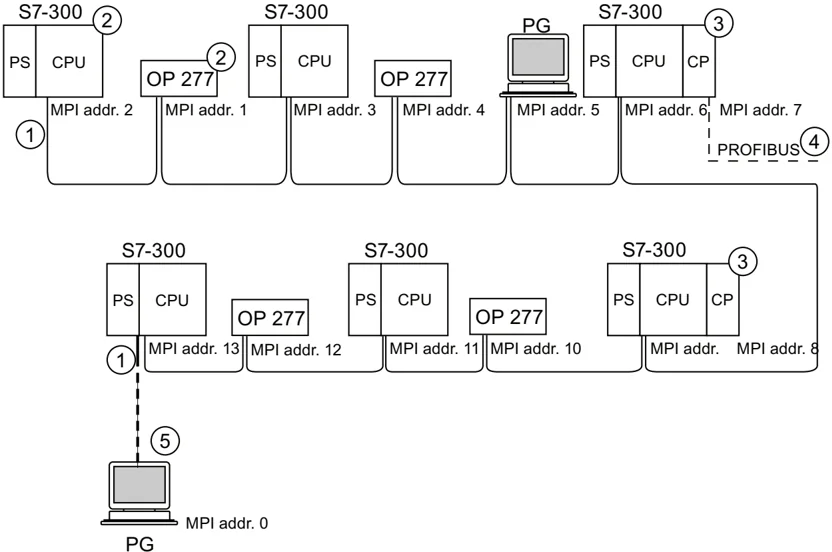
Number Description ① Terminating resistor enabled. ② S7-300 and OP 277 have subsequently been connected to the MPI subnet using their default MPI address. ③ CPU 31xC (except CPU 314C-2 PN/DP), 312, 314, CPU 315-2 DP: You can freely assign the MPI addresses of the CPs/FMs with these CPUs. CPU 314C-2 PN/DP, CPU 317-2 DP, 315-2 PN/DP, 317-2 PN/DP, 319-3 PN/DP: CPs or FMs do not have their own MPI address with these CPUs. ④ In addition to the MPI address, the CP also has a PROFIBUS address (7 in this case). ⑤ Connected via stub cable using the default MPI address only for commissioning/maintenance.
68
Configuring
4.11 Planning subnets
Example: Maximum distances in the MPI subnet
The figure below shows you:
- a possible MPI subnet configuration
- maximum distances possible in an MPI subnet
- the principle of "Line extension" using RS 485 repeaters
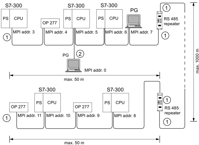
Number Description ① Terminating resistor enabled ② PG connected by means of stub cable for maintenance purposes
69
Configuring 4.11 Planning subnets
Example: Terminating resistor in the MPI subnet
The figure below shows you an example of an MPI subnet and where to enable the terminating resistor.
The figure below illustrates where the terminating resistors must be enabled in an MPI subnet. In this example, the programming device is connected via a stub cable only for the duration of commissioning or maintenance.
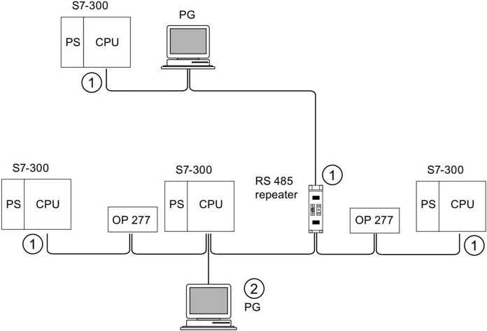
Number Description ① Terminating resistor enabled ② PG connected by means of stub cable for maintenance purposes
WARNING Disturbance of data traffic might occur on the bus. A bus segment must always be terminated at both ends with the terminating resistor. This, for example, is not the case if the last slave with bus connector is off power. The bus connector draws its power from the station, and the terminating resistor is thus disabled. Please make sure that power is always supplied to stations on which the terminating resistor is active. Alternatively, the PROFIBUS terminator can also be used as active bus termination.
70