Debugging functions, diagnostics and troubleshooting
10.8 Diagnostics using status and error LEDs
Table 10-7 BF LED flashes
| Possible problem | CPU reaction | Possible remedies |
|---|---|---|
| The CPU is DP master:• Failure of a connected station• At least one of the configured slaves cannot be accessed.• Incorrect configuration | Call of OB 86, if CPU is in RUN mode and operated DP slaves before the error occurred.CPU switches to STOP if OB 86 is not loaded. | Verify that the bus cable is connected to the CPU, or that the bus is not interrupted.Wait until the CPU has completed its startup. If the LED does not stop flashing, check the DP slaves or evaluate the diagnostic data for the DP slaves. |
| The CPU is active DP slave:Possible causes:• The watchdog time has elapsed.• PROFIBUS DP communication is down.• Wrong PROFIBUS address.• Incorrect configuration | Call of OB 86, if CPU is in RUN mode and communicated as a DP slave with the DP master before the error occurred.CPU switches to STOP if OB 86 is not loaded. | • Check the CPU.• Verify that the bus connector is properly seated.• Check for breaks in the bus cable to the DP master.• Check the configuration data and parameters. |
Reference
Details on the OBs and on the SFCs required for their evaluation are available
- in the STEP 7 Online Help
- in the System Software for S7-300/400, System and Standard Functions Reference Manual
225
Debugging functions, diagnostics and troubleshooting
10.8 Diagnostics using status and error LEDs
10.8.6 Status and error indicators: CPUs with PROFINET interface for the S7-300
Status and Error Indicators: PROFINET devices
Note
The RX and TX LEDs can also be grouped in one LED, e.g., as on CPU 317-2 PN/DP. The RX/TX LED on this device is located, for example, under the front cover.
| LED | LED status | Description of the status | ||
|---|---|---|---|---|
| Not lit | Flashes | Lit | ||
| LINK | – | – | X | There is no connection between the PROFINET interface of your PROFINET device and a communication partner in the Ethernet (a switch, for example). |
| – | X | – | A "Node flash test" initiated in SIMATIC Manager activates flashing of the LINK LED only for the IO devices.The LINK LEDs can also be set to flash on CPUs, for example, by calling the "Search network" function in HW Config (PLC → Ethernet → Edit Ethernet node → Search → Flash).Comment: On CPUs, the common "Node flash test" initiates flashing of the FORCE LED. | |
| X | – | – | The Ethernet connection between the PROFINET interface of the PROFINET device and the communication partner is down. | |
| RX | – | – | X (flickers) | At the current time, data are being received from a communication partner on Ethernet via PROFINET interface of the PROFINET device. |
| X | – | – | No data are currently received via the PROFINET interface. | |
| TX | – | – | X (flickers) | Data are currently sent to a communication partner on Ethernet via the PROFINET interface of the PROFINET device. |
| X | – | – | No data are currently transmitted via the PROFINET interface. | |
| MAINT | X | – | – | There is currently no maintenance request pending. |
| – | – | X | A maintenance request is pending | |
| BF2 or BF3 | – | – | X | Error on the PROFINET interface, communication no longer possible (for example, with a CPU as IO controller, when the connection to the switch is down)Remedy: See the table below |
| – | X | – | The BF LED always flashes if the communication cannot be set up correctly to all devices on the PROFINET IO controller (for example, station failure of one or several IO devices).However, communication is always possible via a port of the PROFINET interface (link to a partner device is active).On a CPU that is operated as intelligent device, the BF LED keeps flashing until at least one controller has correctly set up communication with this I-device.Remedy: See the table below | |
| X | – | – | No error at the PROFINET interface |
226
Debugging functions, diagnostics and troubleshooting 10.8 Diagnostics using status and error LEDs
Remedy of faults at the PROFINET interface - BF2/BF3 LED is lit
Table 10- 8 BF2/BF3 LED is lit
Remedy of faults at the PROFINET interface of an IO controller - BF2/BF3 LED flashes
Table 10- 9 BF2/BF3 LED flashes at a PROFINET IO controller
227
Debugging functions, diagnostics and troubleshooting 10.8 Diagnostics using status and error LEDs
Troubleshooting errors on the PROFINET interface of an I-device - BF2/BF3 LED flashes
Table 10- 10 BF2/BF3 LED flashes on an I-device
228
Debugging functions, diagnostics and troubleshooting
10.8 Diagnostics using status and error LEDs
10.8.7 Status and error indicators: PROFINET IO Devices
Troubleshooting errors on the PROFINET interface of an IO device and in mixed mode with IO controller/I-device - BF LED flashes
Table 10- 11 BF LED flashes on a PROFINET IO device
Tip: Identification of the PROFINET device in the cubicle
When they are first commissioned, PROFINET IO devices must be assigned a device name. In STEP 7/HW Config, you can make the LINK LED of a PROFINET IO device you are naming flash using PLC >Ethernet > Assign device name . This allows you, for example, to clearly identify a PROFINET IO device among several identical devices in a control cabinet.
Maintenance LED
This LED indicates that a maintenance request is pending, for example, loss of synchronization of the own station.
For additional information, refer to the STEP 7 online help.
Debugging functions, diagnostics and troubleshooting 10.9 Diagnostics of DP CPUs
10.9 Diagnostics of DP CPUs
10.9.1 Diagnostics of DP CPUs operating as DP Master
Evaluate diagnostics in the user program The figure below illustrates the procedure for evaluating diagnostics data in the user program.
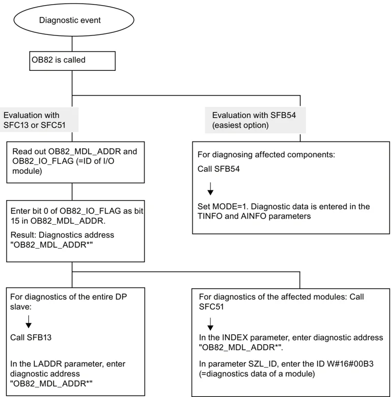
Note: SFC 13 is asynchronous, which means that it may be called multiple times until its state has changed to BUSY=0.
Initial call in OB82, finishing in the cycle
230
Diagnostic addresses for DP masters and DP slaves
For a CPU 31x-2, you assign diagnostic addresses for PROFIBUS DP. When configuring the project, make sure that the DP diagnostic addresses are assigned once to the DP master and once to the DP slave.
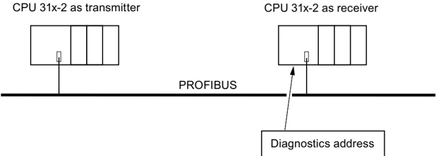
| Description of the DP master configuration | Description of the DP slave configuration |
|---|---|
| When you configure the DP master, assign two different diagnostic addresses for an intelligent slave, that is, one diagnostic address for slot 0, and one for slot 2. Functions of those two addresses:• The diagnostic address for slot 0 is used to report in the master all events relating to the entire slave (station substitute), for example, node failure.• The diagnostic address for slot 2 is used to report events concerning this slot. For example, if the CPU is acting as an I-slave, it returns the diagnostic interrupts for operating mode transitions.From now on, these diagnostic addresses is referred to as assigned to the DP master.These diagnostic addresses are used by the DP master to obtain information about the status of the DP slave or about bus interruptions. | When you configure the DP slave, you also assign it a diagnostic address (in the associated DP slave project).Below, this diagnostic address is referred to as assigned to DP slave.This diagnostic address is used by the DP slave to obtain information on the status of the DP master or on bus interruptions. |
231
Debugging functions, diagnostics and troubleshooting
10.9 Diagnostics of DP CPUs
Event detection
The table below shows how a CPU 31x-2 operating as DP master detects operating mode transitions of a CPU operating as DP slave, or data exchange interruptions.
Table 10- 12 Event detection of CPU 31x2 operating as DP master
Evaluation in the user program
The table below shows how you can, for example, evaluate RUN to STOP transitions of the DP slave in the DP master.
Table 10- 13 Evaluating RUN to STOP transitions of the DP slave in the DP master
Debugging functions, diagnostics and troubleshooting
10.9 Diagnostics of DP CPUs
10.9.2 Reading out slave diagnostic data
The slave diagnostic data is compliant with EN 50170, Volume 2, PROFIBUS. Depending on the DP master, diagnostic data for all DP slaves conforming to standard can be read with STEP 7.
Diagnostic addresses for the receiving station with direct data exchange
For direct data exchange, you assign a diagnostic address in the receiving station:
 CPU 31x-2 as transmitter
CPU 31x-2 as receiver
PROFIBUS
Diagnostics address
Figure 10-2 PROFIBUS DP diagnostics address
In this figure, you see that assign a diagnostic address to the receiving station in your configuration. The receiving station receives information about the status of the transmitting station or about a bus interruption by means of this diagnostic address.
Reading out the diagnostic data
The table below shows you how the various DP master systems can read diagnostic information from a slave.
Table 10- 14 Reading out diagnostic data in the master system, using STEP 5 and STEP 7
233
Debugging functions, diagnostics and troubleshooting
10.9 Diagnostics of DP CPUs
| Automation system with DP master | Blocks or registers in STEP 7 | Application | Additional Information |
|---|---|---|---|
| SFC 51 "RDSYSST" | Reading SSL sublists. In the diagnostic interrupt, call SFC 51 with the SSL ID W#16#00B4 and then read out the SSL of the slave CPU. | System and Standard Functions Reference Manual | |
| SFB 52 "RDREC" and SFC 59 "RD_REC" | Reading the data records of S7 diagnostics (stored in the data area of the user program) | System and Standard Functions Reference Manual | |
| FB 125/FC 125 | Evaluating slave diagnostic data | On the Internet (http://support.automation.siemens.com/WW/view/en/387257) | |
| SIMATIC S5 with IM 308-C operating in DP master mode | FB 192 "IM308C" | Reading slave diagnostic data (store in the data area of the user program) | Distributed I/O System ET 200 Manual |
Example for reading the slave diagnosis with FB 192 "IM308C"
This shows you an example of how to use FB 192 in the STEP 5 user program to read out slave diagnostics data for a DP slave.
Assumptions regarding the STEP 5 user program
For this STEP 5 user program it is assumed that:
- The IM 308-C operating in DP master mode uses the page frames 0 to 15 (number 0 of IM 308-C).
- The DP slave is assigned PROFIBUS address 3.
- Slave diagnostics data should be stored in DB 20. You may also use any other DB.
- Slave diagnostic data consists of 26 bytes.
STEP 5 user program
| STL | Explanation |
|---|---|
| :A DB 30 | |
| :SPA FB 192 | |
| Name :IM308C | |
| DPAD : KH F800 | //Default address range of IM 308-C |
| IMST : KY 0.3 | //IM no. = 0, PROFIBUS address of the DP slave = 3 |
| FCT : KC SD | //function: Read slave diagnostics |
| GCGR : KM 0 | //not evaluated |
| TYP : KY 0, 20 | //S5 data area: DB 20 |
| STAD : KF +1 | //Diagnostic data starting at data word 1 |
| LENG : KF 26 | //Length of diagnostic data = 26 bytes |
| ERR : DW 0 | //Error code storage in DW 0 of DB 30 |
Debugging functions, diagnostics and troubleshooting
10.9 Diagnostics of DP CPUs
Example of reading out S7 diagnostic data with SFC 59 "RD REC"
Here you will find an example of how to use SFC 59 in the STEP 7 user program to read S7 diagnostics data records for a DP slave. The process of reading the slave diagnostics is similar for SFC 13.
Assumptions regarding the STEP 7 user program
Exceptions for this STEP 7 user program:
- Diagnostic data for the input module at address 200H is to be read.
- Data record 1 is to be read out.
- Data record 1 is to be stored in DB 10.
STEP 7 user program
STLExplanation CALL SFC 59 REQ :=TRUE //Request to read IOID :=B#16#54 //Identifier of the address range, here the I/O input //Logical address of the module LADDR :=W#16#200 //Data record 1 is to be read RECNUM :=B#16#1 //An error code is output if an error occurs RET_VAL :=MW2 //Read operation not finished BUSY :=M0.0 //DB 10 is target area for the read data record 1 RECORD :=P# DB10.DBX 0.0 BYTE 240
Note:
Data is only returned to the target area if BUSY is reset to 0 and if no negative RET_VAL has occurred.
235
Debugging functions, diagnostics and troubleshooting
10.9 Diagnostics of DP CPUs
Diagnostic addresses
For a CPU 31x-2, you assign diagnostic addresses for PROFIBUS DP. When configuring the project, make sure that the DP diagnostic addresses are assigned once to the DP master and once to the DP slave.
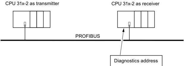
Figure 10-3 PROFIBUS DP diagnostics address
| Description of the DP master configuration | Description of the DP slave configuration |
|---|---|
| When you configure the DP master, assign two different diagnostic addresses for an intelligent slave, that is, one diagnostic address for slot 0, and one for slot 2. Functions of those two addresses:• The diagnostics address for slot 0 is used to report in the master all events relating to the entire slave (station substitute), for example, node failure.• The diagnostics address for slot 2 is used to report events concerning this slot. For example, if the CPU is acting as an I-slave, it returns the diagnostic interrupts for operating mode transitions.From now on, these diagnostic addresses is referred to as assigned to the DP master.These diagnostic addresses are used by the DP master to obtain information about the status of the DP slave or about bus interruptions. | When you configure the DP slave, you also assign it a diagnostic address (in the associated DP slave project).Below, this diagnostic address is referred to as assigned to DP slave.This diagnostic address is used by the DP slave to obtain information on the status of the DP master or on bus interruptions. |
236
Debugging functions, diagnostics and troubleshooting 10.9 Diagnostics of DP CPUs
Event recognition
The table below shows how CPU 31x-2 operating as DP slave recognized operating state transitions or data exchange interruptions.
Table 10- 15 Event recognition of CPUs 31x-2 operating in DP slave mode
Evaluation in the user program
The table below shows how you can, for example, evaluate RUN-STOP transitions of the DP master in the DP slave (see also the previous table).
Table 10- 16 Evaluating RUN-STOP transitions in the DP Master/DP Slave
237
Debugging functions, diagnostics and troubleshooting 10.9 Diagnostics of DP CPUs
10.9.3 Interrupts on the DP Master
Interrupts with S7 DP master
Process interrupts from an intelligent slave with SFC 7 In the CPU 31x-2 operating in DP slave mode, you can trigger a user-defined process interrupt from the DP master from the user program.
The call of SFC 7 "DP_PRAL" triggers a call of OB 40 in the user program of the DP master. The SFC 7 allows you to forward interrupt information to the DP master in a double word. This information can then be evaluated in the OB40_POINT_ADDR variable in the OB40. The interrupt information can be programmed user-specific. You will find a detailed description of SFC7 "DP_PRAL" in the System Software for S7-300/400, System and Standard Functions Reference Manual.
Setting user-defined interrupts of Intelligent Slaves using SFB 75 In the CPU 31x-2 operating in DP slave mode, you can trigger user-defined interrupts from the user program in the DP master. SFB 75 "SALRM" is used to send a process or diagnostic interrupt from a slot in the transfer area (virtual slot) to the associated DP master from the user program on an intelligent slave. This starts the associated OB on the DP master.
Additional interrupt-specific information may be included. You can read this additional information in the DP master using SFB 54 "RALRM."
Interrupts with another DP master When CPU 31x-2 operates with another DP master, an image of these interrupts is created in its device-specific diagnostic data. You have to post-process the relevant diagnostic events in the DP master's user program.
Note In order to allow the evaluation of diagnostics and process interrupts by means of device-specific diagnostics using a different DP master, please note that:
The DP master should be able to save the diagnostics messages to its ring buffer. For example, if the DP master can not save the diagnostic messages, only the last incoming diagnostic message would be saved.
In your user program, you have to poll the relevant bits in the device-specific diagnostic data in cyclic intervals. Make allowances for the PROFIBUS DP bus cycle time, for example, to be able to poll these bits at least once and in synchronism to the bus cycle time.
With an IM 308-C operating in DP master mode, you cannot utilize process interrupts in device-specific diagnostics, because only incoming events are reported, rather than outgoing events.
238
Debugging functions, diagnostics and troubleshooting 10.9 Diagnostics of DP CPUs
10.9.4 Structure of the slave diagnostics when the CPU is operated as I-slave
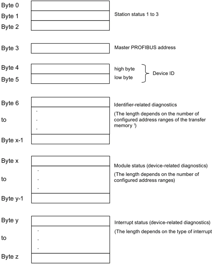
Syntax of the diagnostics datagram for slave diagnostics
Byte 0 Byte 1 Byte 2 Station status 1 to 3
Byte 3 Master PROFIBUS address
Byte 4 high byte Device ID Byte 5 low byte
Byte 6 Identifier-related diagnostics (The length depends on the number of configured address ranges of the transfer memory ¹) to . . . Byte x-1
Byte x Module status (device-related diagnostics) (The length depends on the number of configured address ranges) to . . . Byte y-1
Byte y Interrupt status (device-related diagnostics) (The length depends on the type of interrupt) to . . . Byte z
¹ Exception: In the case of an incorrect configuration from the DP master, the DP slave interprets 35 configured address ranges (46H in Byte 6)
Figure 10-4 Structure of slave diagnostic data
239
Debugging functions, diagnostics and troubleshooting 10.9 Diagnostics of DP CPUs
Station Status 1
Table 10- 17 Structure of station status 1 (Byte 0)
Debugging functions, diagnostics and troubleshooting 10.9 Diagnostics of DP CPUs
Station Status 2
Table 10- 18 Structure of station status 2 (Byte 1)
Station Status 3
Table 10- 19 Structure of station status 3 (Byte 2)
Master PROFIBUS address
The "Master PROFIBUS address" diagnostic byte stores the DP address of the DP master:
- that has configured the DP slave and
- that has read and write access to the DP slave
Table 10- 20 Structure of the Master PROFIBUS address (byte 3)
241
Debugging functions, diagnostics and troubleshooting 10.9 Diagnostics of DP CPUs
Device ID
The device ID is a manufacturer ID containing a code which specifies the type of the DP slave.
Table 10- 21 Structure of the device ID (bytes4, 5)
242
Debugging functions, diagnostics and troubleshooting
10.9 Diagnostics of DP CPUs
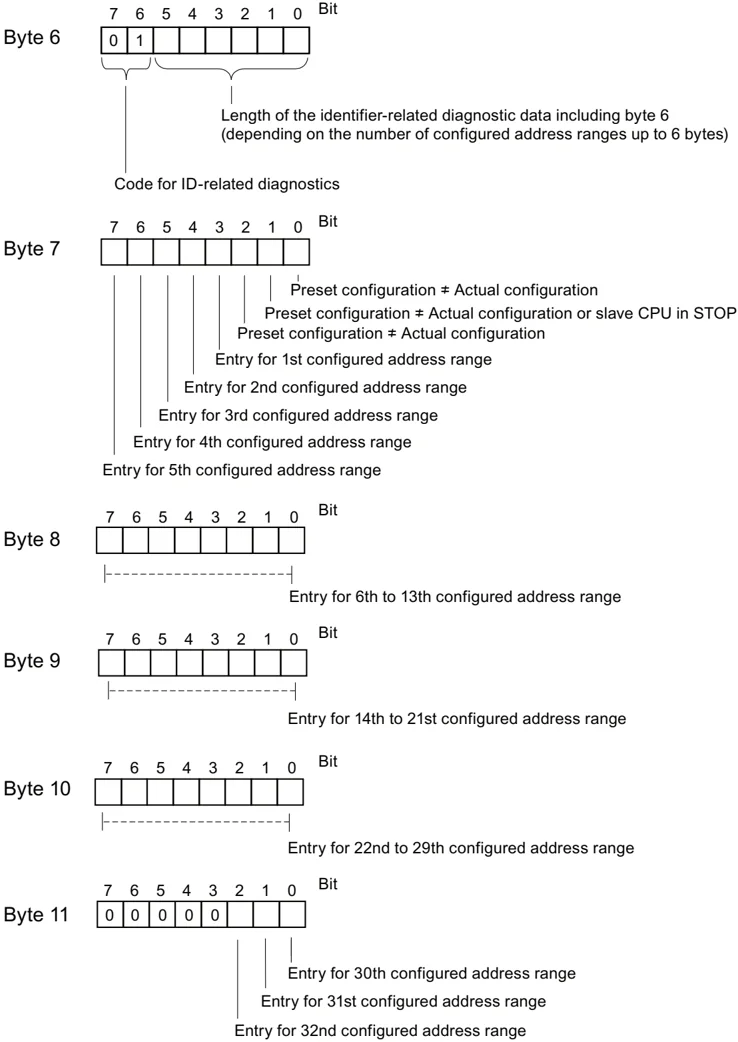
Structure of identifier-related diagnostics of CPU 31x-2/CPU 319-3
Module diagnostics indicate the configured address range of intermediate memory that has received an entry.
Byte 6 7 6 5 4 3 2 1 0 Bit 0 1 Length of the identifier-related diagnostic data including byte 6 (depending on the number of configured address ranges up to 6 bytes) Code for ID-related diagnostics
Byte 7 7 6 5 4 3 2 1 0 Bit Preset configuration ≠ Actual configuration Preset configuration ≠ Actual configuration or slave CPU in STOP Preset configuration ≠ Actual configuration Entry for 1st configured address range Entry for 2nd configured address range Entry for 3rd configured address range Entry for 4th configured address range Entry for 5th configured address range
Byte 8 7 6 5 4 3 2 1 0 Bit Entry for 6th to 13th configured address range
Byte 9 7 6 5 4 3 2 1 0 Bit Entry for 14th to 21st configured address range
Byte 10 7 6 5 4 3 2 1 0 Bit Entry for 22nd to 29th configured address range
Byte 11 7 6 5 4 3 2 1 0 Bit 0 0 0 0 0 Entry for 30th configured address range Entry for 31st configured address range Entry for 32nd configured address range
Figure 10-5 Identifier-related diagnostic data
243
Debugging functions, diagnostics and troubleshooting
10.9 Diagnostics of DP CPUs
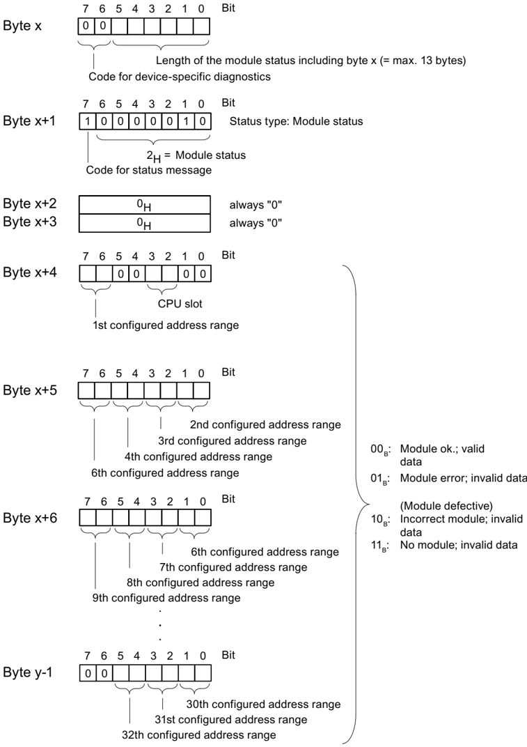
Structure of the module status
The module status reflects the status of the configured address ranges, and provides detailed ID-specific diagnostics with respect to the configuration. The module status follows the identifier-related diagnostics and consists of a maximum of 13 bytes.
Byte x 7 6 5 4 3 2 1 0 Bit [0][0][ ][ ][ ][ ][ ][ ] Length of the module status including byte x (= max. 13 bytes) Code for device-specific diagnostics
Byte x+1 7 6 5 4 3 2 1 0 Bit [1][0][0][0][0][0][1][0] Status type: Module status $2_H$ = Module status Code for status message
Byte x+2 $0_H$ always "0" Byte x+3 $0_H$ always "0"
Byte x+4 7 6 5 4 3 2 1 0 Bit [ ][ ][0][0][ ][ ][0][0] CPU slot 1st configured address range
Byte x+5 7 6 5 4 3 2 1 0 Bit [ ][ ][ ][ ][ ][ ][ ][ ] 2nd configured address range 3rd configured address range 4th configured address range 6th configured address range
Byte x+6 7 6 5 4 3 2 1 0 Bit [ ][ ][ ][ ][ ][ ][ ][ ] 6th configured address range 7th configured address range 8th configured address range 9th configured address range ... ...
Byte y-1 7 6 5 4 3 2 1 0 Bit [0][0][ ][ ][ ][ ][ ][ ] 30th configured address range 31st configured address range 32th configured address range
00_B: Module ok.; valid data 01_B: Module error; invalid data (Module defective) 10_B: Incorrect module; invalid data 11_B: No module; invalid data
Figure 10-6 Structure of the module status for CPU 31xC
244
Debugging functions, diagnostics and troubleshooting
10.9 Diagnostics of DP CPUs
Structure of the interrupt status
The interrupt status of module diagnostics provides details on a DP slave. Device-related diagnostics starts at byte y and has a maximum length of 20 bytes.
The following figure describes the structure and content of the bytes for a configured address range of transfer memory.
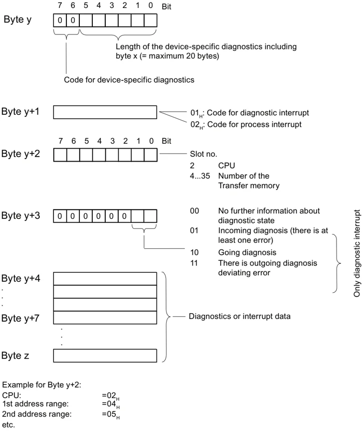
Example for Byte y+2: CPU: =02H 1st address range: =04H 2nd address range: =05H etc.
Figure 10-7 Device-specific diagnostics
Structure of the interrupt data for a process interrupt (from byte y+4)
During a hardware interrupt (in byte y+1, code 02H stands for hardware interrupt), as of byte y+4, the four bytes of interrupt information which you transferred in the I-slave using SFC 7 "DP_PRAL" or SFB 75 "SALRM" during generation of the hardware interrupt for the master are transferred.
245
Debugging functions, diagnostics and troubleshooting 10.9 Diagnostics of DP CPUs
Structure of the interrupt data when a diagnostic interrupt is generated in response to an operating status change by the intelligent slave (after byte y+4)
Byte y+1 contains the code for a diagnostic interrupt ($01_H$). The diagnostic data contains the 16 bytes of status information from the CPU. The figure below shows the allocation of the first four bytes of diagnostic data. The next 12 bytes are always 0.
The data in these bytes correspond to the contents of data record 0 of diagnostic data in STEP 7 (in this case, not all bits are used).
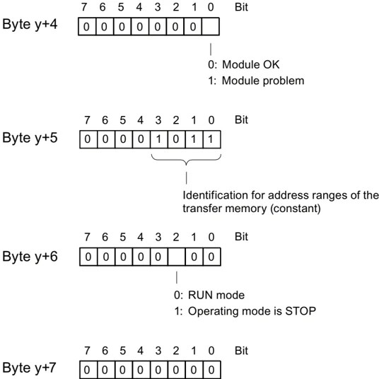
Note: Byte y+8 to Byte y+19 are always 0.
Figure 10-8 Bytes y+4 to y+7 for a diagnostic interrupt (operating status change by intelligent slave)
246
Debugging functions, diagnostics and troubleshooting 10.10 Diagnostics of PROFINET CPUs
Structure of the interrupt data when a diagnostic interrupt is generated by SFB 75 on the I-slave (as of byte y+4)
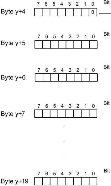
Figure 10-9 Bytes y+4 to y+19 for the diagnostics interrupt (SFB75)
10.10 Diagnostics of PROFINET CPUs
10.10.1 Diagnostics options of PROFINET IO
Diagnostics Concept
PROFINET IO supports you with an integrated diagnostics concept. The diagnostics concept of PROFINET IO is similar to that of PROFIBUS DP.
The diagnostics functions allow you
- to react to an error (event-related diagnostics, evaluation of interrupts) or
- to check the current status of the AS (status-related diagnostics).
247
Debugging functions, diagnostics and troubleshooting
10.10 Diagnostics of PROFINET CPUs
Overview of diagnostics information
You have three options of obtaining diagnostics information:
- Diagnostics using status LEDs
| Diagnostics option | Benefits | For detailed information refer ... |
|---|---|---|
| LEDs on a PROFINET interface | The LED displays indicate:• whether data are being sent or received• communication error. | this manual,chapter: Status and Error Indicators:CPUs with PROFINET interface for the S7-300 |
- Diagnostics using the STEP 7 and NCM PC configuration and engineering tool
| Diagnostics option | Benefits | For detailed information refer ... |
|---|---|---|
| Online diagnostics using a PG/PC/HMI | This allows you to evaluate the current status of your automation system. | the System Manual: PROFINET System Description,chapter: Support by STEP 7/NCM PC |
| Reporting system errors | Diagnostic information is output in plain text format to the PC / HMI. | the System Manual: PROFINET System Description,chapter: Support by STEP 7/NCM PC |
| Network diagnostics | The SNMP protocol allows you to determine the network infrastructure. | this manual,chapter: Network infrastructure diagnostics (SNMP) |
- Diagnostics in the STEP 7 user program
| Diagnostics option | Benefits | For detailed information refer ... |
|---|---|---|
| Reading system status lists (SSLs) | The SSLs will help you to track down an error. | the System Manual: PROFINET System Description,chapter: Evaluation of Diagnostics in the User ProgramReference manual: System software for S7-300/400 System and Standard Functions |
| Reading diagnostics data records | You can obtain detailed information about the type and source of faults by reading the diagnostic data records. | the System Manual: PROFINET System Description,chapter: Evaluation of Diagnostics in the User Program |
| Diagnostic interrupt | Can be used to evaluate diagnostics data in the user program. | the System Manual: PROFINET System Description,chapter: Evaluation of Diagnostics in the User Program |
248
Debugging functions, diagnostics and troubleshooting 10.10 Diagnostics of PROFINET CPUs
Evaluation of diagnostics information
PROFINET IO supports a vendor-independent structure of data records with diagnostics information. Diagnostics information is only generated for faulty channels.
The SSLs, SFB54 and SFB52 were enhanced to include information about the status of the PROFINET IO systems and the diagnostics information for an S7 user program:
- To read module status information of the PROFINET IO system, use SFC 51 (read system status lists) to read the information from SSL 0x0X96, for example.
- Call SFB52 (read data record) to read status-related diagnostics data records directly from a faulty module.
- Status-related diagnostic data is error information, for example.
- Call SFB54 (read additional interrupt info) in the corresponding error OB to read event-related diagnostics data records from a module.
- Event-related diagnostic data is interrupt information of the error OBs, for example.
Additional Information
Additional information about diagnostics and diagnostics data, on the structure of diagnostics data records and on SSLs for PROFINET is available in:
- the From PROFIBUS DP to PROFINET IO Programming Manual
- the PROFINET System Description System Manual
- the System Software for S7-300/400, System and Standard Functions Reference Manual
- in the STEP 7 Online Help
10.10.2 Maintenance
Enhanced maintenance concept
PROFINET devices support the comprehensive diagnostics and maintenance concept according to the IEC standard61158-6-10.
In addition to "ok" and "faulty" information, the PROFINET components can also display information for preventive maintenance when operating with STEP 7 V5.4 Servicepack 1 or higher.
Preventive maintenance is displayed, for example, if the attenuation of a fiber-optic cable deteriorates.
249
Debugging functions, diagnostics and troubleshooting
10.10 Diagnostics of PROFINET CPUs
Maintenance information
Maintenance information returns maintenance priorities. The concept distinguishes between maintenance information based on two levels:
| Maintenance information | Symbol in STEP 7 | Status of the MAINT LED | Example |
|---|---|---|---|
| Maintenance required (maintenance required):Maintenance recommended | green wrench | Off | The attenuation on a fiber-optic conductor is becoming too high. Although operation is still possible, the transmission link may fail completely in the near future. |
| Maintenance request (maintenance demanded):Maintenance required | yellow wrench | Yellow | Failure of the synchronization master in a synchronization domain for the IRT operation of a PNIO system. |
Additional Information
Additional information is available in:
- the From PROFIBUS DP to PROFINET IO Programming Manual
- PROFINET System Description system manual
- CPU 31xC and CPU 31x, Manual, Technical Data, chapter Webserver
- in the STEP 7 Online Help
See also
Diagnostics options of PROFINET IO (Page 247)
General technical specifications
11.1 Standards and certifications
Introduction Contents of general technical specifications:
- standards and test values satisfied by modules of the S7-300 automation system
- test criteria of S7-300 modules.
Note Information about the nameplate You will find the current identifiers and approvals on the rating plate of the respective product.
Safety information
WARNING Personal injury and damage to property may occur. In potentially explosive environments, there is a risk of personal injury and damage to property if you remove S7-300 connectors in runtime. In potentially explosive environments, always isolate the S7-300 before you remove any connectors.
WARNING Explosion hazard If you replace components, compliance with Class I, DIV. 2 could be compromised.
WARNING This device is only appropriate for use in Class I, Div. 2, Group A, B, C, D, or in non-hazardous areas.
Test logos and their meaning The section below describes the test logos attached to the module and explains their meaning.
251



General technical specifications 11.1 Standards and certifications
CE Label
 The S7-300 automation system satisfies requirements and safety-related objectives according to EC Directives listed below, and conforms with the harmonized European standards (EN) for programmable controllers announced in the Official Journals of the European Community:
- 2006/95/EC "Electrical Equipment Designed for Use within Certain Voltage Limits" (Low-Voltage Directive)
- 2004/108/EC "Electromagnetic Compatibility" (EMC Directive)
- 94/9/EC "Equipment and protective systems intended for use in potentially explosive atmospheres" (Explosion Protection Directive)
The EC declaration of conformity is held on file available to competent authorities at: Siemens AG Industry Sector I IA AS R&D DH A P.O. Box 1963 D-92209 Amberg
These files are also available for download on the Customer Support Internet pages, keyword "Declaration of Conformity".
UL approval
 Underwriters Laboratories Inc., complying with
- UL 508 (Industrial Control Equipment)
CSA approval
Canadian Standards Association to
- C22.2 No. 142 (Process Control Equipment) or
cULus approval
 Underwriters Laboratories Inc., complying with
- UL 508 (Industrial Control Equipment)
- CSA C22.2 No. 142 (Process Control Equipment) or
252

General technical specifications 11.1 Standards and certifications
cULus HAZ. LOC approval
 Underwriters Laboratories Inc., complying with
- UL 508 (Industrial Control Equipment)
- CSA C22.2 No. 142 (Process Control Equipment)
- UL 1604 (Hazardous Location)
- CSA C22.2 No. 213 (Hazardous Location) APPROVED for use in Class I, Division 2, Group A, B, C, D Tx; Class I, Zone 2, Group IIC Tx
FM approval
 Factory Mutual Research (FM) to
Approval Standard Class Number 3611, 3600, 3810
APPROVED for use in Class I, Division 2, Group A, B, C, D Tx;
Class I, Zone 2, Group IIC Tx
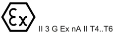
ATEX approval
In accordance with EN 60079-15 (Electrical Apparatus for Potentially Explosive Atmospheres; Type of Protection "n") and EN 60079-0 (Electrical apparatus for potentially explosive gas atmospheres - Part 0: General Requirements)
 II 3 G Ex nA II T4..T6
WARNING Personal injury and damage to property may occur. In potentially explosive environments, there is a risk of personal injury and damage to property if you remove S7-300 connectors in runtime. In potentially explosive environments, always isolate the S7-300 before you remove any connectors.
253

General technical specifications
11.1 Standards and certifications
Tick mark for Australia and New Zealand
The S7-300 automation system meets requirements of standards to AS/NZS CISPR 16.
Note
The UL/CSA or cULus approvals for your product are specified by the identifiers on the rating plate.
IEC 61131
The S7-300 automation system satisfies requirements and criteria to IEC 61131-2 (Programmable Controllers, Part 2: Equipment requirements and tests).
Marine approval
Classification societies:
- ABS (American Bureau of Shipping)
- BV (Bureau Veritas)
- DNV (Det Norske Veritas)
- GL (Germanischer Lloyd)
- LRS (Lloyds Register of Shipping)
- Class NK (Nippon Kaiji Kyokai)
Use in industrial environments
SIMATIC products are designed for industrial applications.
Table 11-1 Use in industrial environments
| Field of application | Noise emission requirements | Noise immunity requirements |
|---|---|---|
| Industry | EN 61000-6-4: 2007 | EN 61000-6-2: 2005 |
General technical specifications 11.2 Electromagnetic compatibility
Use in residential areas
Note The S7-300 is intended for use in industrial environments and can cause interference on radio/television reception if operated in residential areas.
To operate an S7-300 in a residential area, it's RF emission must comply with Limit Value Class B to EN 55011. Suitable measures for achieving RF interference level Class B include, for example:
- S7-300 installation in grounded switch cabinets / cubicles
- Use of noise filters in the supply lines
11.2 Electromagnetic compatibility
Definition
Electromagnetic compatibility (EMC) is the ability of an electrical installation to function satisfactorily in its electromagnetic environment without interfering with that environment. The S7-300 modules also satisfy requirements of EMC legislation for the European domestic market. Compliance of the S7-300 system with specifications and directives on electric design is prerequisite.
Pulse-shaped disturbance
The table below shows the electromagnetic compatibility of S7 modules in areas subject to pulse-shaped interference.
255
General technical specifications 11.2 Electromagnetic compatibility
Additional measures
When connecting an S7-300 system to the public network, always ensure compliance with Limit Value Class B to EN 55022.
Sinusoidal disturbance
The table below shows the electromagnetic compatibility of the S7-300 modules in areas subject to sinusoidal interference.
- RF radiation
\begin{tabular}{|l|l|l|} \hline \multicolumn{2}{|l|}{RF radiation to IEC 61000-4-3} & corresponds with degree \ \multicolumn{2}{|l|}{Electromagnetic RF field, amplitude-modulated} & of severity \ \hline 80 to 1000 MHz; 1.4 to 2 GHz & 2.0 GHz to 2.7 GHz & \multirow{3}{*}{3, 2, 1} \ \cline{1-2} 10 V/m & 1 V/m & \ \cline{1-2} 80 % AM (1 kHz) & & \ \hline \end{tabular}
- RF coupling
\begin{tabular}{|l|l|} \hline RF coupling to IEC 61000-4-6 & corresponds with degree \ & of severity \ \hline 0.15 to 80 MHz & \multirow{4}{*}{3} \ \cline{1-1} 10 V_rms unmodulated & \ \cline{1-1} 80 % AM (1 kHz) & \ \cline{1-1} 150 \Omega source impedance & \ \hline \end{tabular}
Emission of radio interference
Electromagnetic interference emission to EN 55016: Limit value class A (measured at a distance of 10 m).
\begin{tabular}{|l|l|} \hline Frequency & Emitted interference \ \hline 30 MHz to 230 MHz & < 40 dB (\muV/m)Q \ \hline 230 MHz to 1000 MHz & < 47 dB (\muV/m)Q \ \hline \end{tabular}
Noise emission via AC mains to EN 55016: Limit value class A, Group 1.
\begin{tabular}{|l|l|} \hline Frequency & Emitted interference \ \hline 0.15 to 0.5 MHz & < 79 dB (\muV/m)Q \ & < 66 dB (\muV/m)M \ \hline 0.5 MHz to 5 MHz & < 73 dB (\muV/m)Q \ & < 60 dB (\muV/m)M \ \hline 5 MHz to 30 MHz & < 73 dB (\muV/m)Q \ & < 60 dB (\muV/m)M \ \hline \end{tabular}
256
General technical specifications 11.3 Transportation and storage conditions for modules
11.3 Transportation and storage conditions for modules
Introduction
The shipping and storage conditions of S7-300 modules surpass requirements to IEC 61131-2. The data below apply to modules shipped or put on shelf in their original packing.
The modules are compliant with climatic conditions to IEC 60721-3-3, Class 3K7 (storage), and with IEC 60721-3-2, Class 2K4 (shipping.)
Mechanical conditions are compliant with IEC 60721-3-2, Class 2M2.
Shipping and storage conditions for modules
257
11.4 Mechanical and climatic environmental conditions for S7-300 operation
Operating conditions
S7-300 systems are designed for stationary use in weather-proof locations. The operating conditions surpass requirements to DIN IEC 60721-3-3.
- Class 3M3 (mechanical requirements)
- Class 3K3 (climatic requirements)
Use with additional measures
The S7-300 may not be used under the conditions outlined below without taking additional measures:
- At locations with a high degree of ionizing radiation
- In aggressive environments caused, for example, by
- The development of dust
- Corrosive vapors or gases
- Strong electric or magnetic fields
- In installations requiring special monitoring, for example
- Elevators
- Electrical plants in potentially hazardous areas
An additional measure could be an installation of the S7-300 in a cabinet or housing.
Mechanical environmental conditions
The table below shows the mechanical environmental conditions in the form of sinusoidal oscillations.
| Frequency band | Continuous | Infrequently |
|---|---|---|
| 10 ≤ f ≤ 58 Hz | 0,0375 mm amplitude | 0.75 mm amplitude |
| 58 ≤ f ≤ 150 Hz | 0,5 g constant acceleration | 1 g constant acceleration |
Reducing vibrations
If your S7-300 modules are exposed to severe shock or vibration, take appropriate measures to reduce acceleration or the amplitude.
We recommend the installation of the S7-300 on damping materials (for example, rubber-bonded-to-metal mounting.)
General technical specifications
11.4 Mechanical and climatic environmental conditions for S7-300 operation
Test of mechanical environmental conditions
The table below provides important information with respect to the type and scope of the test of ambient mechanical conditions.
| Condition tested | Test Standard | Comment |
|---|---|---|
| Vibration | Vibration test to IEC 60068-2-6 (sinusoidal) | Type of oscillation: Frequency sweeps with a rate of change of 1 octave/minute.5 Hz ≤ f ≤ 9 Hz, 3.5 mm constant amplitude9 Hz ≤ f ≤ 150 Hz, 1 g constant accelerationDuration of oscillation: 10 frequency sweeps per axis at each of three vertically aligned axes |
| Shock | Shock, tested to IEC 60068-2-27 | Type of shock: Half-sineShock intensity: 15 g peak value, 11 ms durationDirection of shock: 3 shocks in each direction (+/-) at each of three vertically aligned axes |
Climatic environmental conditions
The S7-300 may be operated on following environmental conditions:
| Environmental conditions | Permissible range | Comments |
|---|---|---|
| Temperature:horizontal mounting position:vertical mounting position: | 0°C to 60 °C0°C to 40 °C | - |
| Relative humidity | from 10 to 95% | No condensation, corresponds to relative humidity (RH) Class 2 to IEC 61131, Part 2 |
| Barometric pressure | 1080 hPa to 795 hPa | Corresponds with an altitude of -1000 m to 2000 m |
| Concentration of pollutants | SO₂: < 0.5 ppm;RH < 60 %, no condensationH₂S: < 0.1 ppm;RH < 60 %, no condensation | Test: 10 ppm; 4 daysTest: 1 ppm; 4 days |
| ISA-S71.04 severity level G1; G2; G3 | - |
259
General technical specifications
11.5 Specification of dielectric tests, protection class, degree of protection, and rated voltage of S7-300
Test voltage
Proof of dielectric strength must be provided in the type test at a test voltage to IEC 61131-2:
| Circuits with rated voltage Vₑ to other circuits or ground. | Test voltage |
|---|---|
| < 50 V | 500 VDC |
| < 150 V | 2500 V DC |
| < 250 V | 4000 V DC |
Protection class
Protection class I to IEC 60536, i.e., a protective conductor must be connected to the mounting rail!
Protection against the ingress of foreign matter and water
- Degree of protection IP 20 to IEC 60529, i.e., protection against contact with standard probes.
- No protection against the ingress of water.
11.6 Rated voltages of S7-300
Rated operating voltages
The S7-300 modules operate at different rated voltages. The table shows the rated voltages and corresponding tolerances.
| Rated voltages | Tolerance |
|---|---|
| 24 V DC | 19.2 V DC to 28.8 V DC |
| 120 VAC | 93 VAC to 132 VAC |
| 230 VAC | 187 VAC to 264 VAC |