Installation Sequence
We will start by showing you the sequence of steps you have to follow to install your system. Then we will go on to explain the basic rules that you should follow, and how you can modify an existing system.
I nstallation procedure

Basic rules for trouble-free operation of the S7 system
In view of the many and versatile applications, we can only provide basic rules for the electrical and mechanical installation in this section.
You have to at least keep to these basic rules in order to obtain a fully functional SIMATIC-S7 system.
23
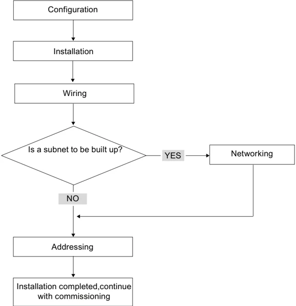
Installation Sequence
Modifying the existing S7 system structure
To modify the configuration of an existing system, proceed as described earlier.
Note
When adding a new signal module, always refer to the relevant module information.
Reference
Also refer to the description of the various modules in the manual: SIMATIC S7-300 Automation Systems, Module Data Manual.
24
S7-300 components
3.1 Example of an S7-300 configuration
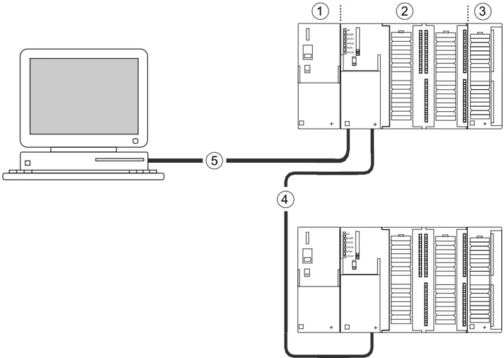
| Number | Description |
|---|---|
| ① | Power supply (PS) module |
| ② | Central processing unit (CPU); the example in the diagram shows a CPU 31xC with integrated I/O. |
| ③ | Signal module (SM) |
| ④ | PROFIBUS bus cable |
| ⑤ | Cable for connecting a programming device (PG) |
You use a programming device (PG) to program the S7300 PLC. Use the PG cable to interconnect the PG with the CPU.
To commission or program a CPU with PROFINET connection, you also have the choice to connect the programming device to the PROFINET port of the CPU via Ethernet cable.
Several S7-300 CPUs communicate with one another and with other SIMATIC S7 PLCs via the PROFIBUS cable. Several S7-300 are connected via the PROFIBUS bus cable.
25
S7-300 components 3.2 Overview of the most important S7-300 modules
3.2 Overview of the most important S7-300 modules
You can choose from a number of modules for installing and commissioning the S7-300. The most important modules and their functions are shown below.
Table 3- 1 S7-300 components:
26
S7-300 components
3.2 Overview of the most important S7-300 modules
| Component | Function | Illustration |
|---|---|---|
| Signal modules (SM)• Digital input modules• Digital output modules• Digital input/output module• Analog input modules• Analog output modules• Analog I/O modulesAccessories:• Front connectors | The SM matches different process signal levels to the S7-300. | |
| Function modules (FM)Accessories:• Front connectors | The FM performs time-critical and memory-intensive process signal processing tasks.Positioning or controlling, for example | |
| Communication processor (CP)Accessories: Connecting cable | The CP relieves the CPU of communication tasks.Example: CP 342-5 DP for connecting to PROFIBUS DP | |
| SIMATIC TOP connectAccessories:• Front connector module with ribbon cable terminals | Wiring of digital modules | |
| Interface module (IM)Accessories:• Connecting cable | The IM connects the various rows in an S7-300 with one another. | |
| PROFIBUS bus cable with bus connector | Connects the nodes of an MPI or PROFIBUS subnet with one another. | |
| PG cable | Connects a PG/PC to a CPU | |
| RS 485 repeaterRS 485 Diagnostic Repeater | The repeater is used to amplify the signals and to couple segments of an MPI or PROFIBUS subnet. |
CPU 31xC and CPU 31x: InstallationOperating Instructions, 03/2011, A5E00105492-12 27
S7-300 components
3.2 Overview of the most important S7-300 modules
| Component | Function | Illustration |
|---|---|---|
| Switch | A switch is used to interconnect the Ethernet nodes. | |
| Twisted-pair cables with RJ45 connectors. | Interconnects devices with Ethernet interface (a switch with a CPU 317-2 PN/DP, for example) | |
| Programming device (PG) or PC with the STEP 7 software package | You need a PG to configure, set parameters for, program and test your S7-300. |
28
Configuring
4.1 Overview
There, you can find all the necessary information
- for the mechanical configuration of an S7-300,
- for the electrical configuration of an S7-300,
- that has to be observed in networking.
Reference
For more detailed information, refer to
- the Communication with SIMATIC manual or
- the SIMATIC NET twisted pair and fiber optic networks manual (6GK1970-1BA10-0AA0)
4.2 Basic configuration principles
Important information for engineering
WARNING Open equipment S7-300 modules are open equipment. That is, the S7-300 must be installed in a cubicle, cabinet or electrical control room which can only be accessed using a key or tool. Only trained or authorized personnel are allowed access to such cubicles, cabinets or electrical operating rooms.
CAUTION Operation of an S7-300 in plants or systems is defined by special set of rules and regulations, based on the relevant field of application. Observe the safety and accident prevention regulations for specific applications, for example, the machine protection directives. This chapter and the appendix General rules and regulations on S7-300 operation provide an overview of the most important rules you need to observe when integrating an S7-300 into a plant or a system.
29


Configuring 4.2 Basic configuration principles
Central unit (CU) and expansion module (EM) An S7-300 PLC consists of a central unit (CU) and of one or multiple expansion modules. The rack containing the CPU is the central unit (CU). Racks equipped with modules and connected to the CU form the expansion modules (EMs) of the system.
Use of an expansion module (EM) You can use EMs if the CU runs out of slots for your application. When using EMs, you might require additional power supply modules in addition to the extra racks and interface modules (IM). When using interface modules you must ensure compatibility of the partner stations.
Racks The rack for your S7-300 is a mounting rail. You can use this rail to mount all modules of your S7-300 system.
30
Configuring 4.2 Basic configuration principles
Horizontal and vertical installation
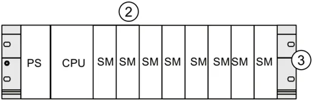
You can mount an S7-300 either vertically or horizontally. The following ambient air temperatures are permitted:
- Vertical assembly: 0 °C to 40 °C
- Horizontal assembly: 0 °C to 60 °C
Always install the CPU and power supply modules on the left or at the bottom.
Number Description ① Vertical structure of the S7-300 ② Horizontal structure of the S7-300 ③ Mounting rail
31
Configuring 4.3 Component dimensions
4.3 Component dimensions
Length of the mounting rails
Table 4- 1 Mounting rails - Overview \begin{tabular}{|l|l|l|} \hline Mounting rail length & Usable length for modules & Order number \ \hline 160 mm & 120 mm & 6ES7390-1AB60-0AA0 \ \hline 482.6 mm & 450 mm & 6ES7390-1AE80-0AA0 \ \hline 530 mm & 480 mm & 6ES7390-1AF30-0AA0 \ \hline 830 mm & 780 mm & 6ES7390-1AJ30-0AA0 \ \hline 2000 mm & cut to length as required & 6ES7390-1BC00-0AA0 \ \hline \end{tabular}
In contrast to other rails, the 2 m mounting rail is not equipped with any fixing holes. These must be drilled, allowing optimal adaptation of the 2 m rail to your application.
Installation Dimensions of the Modules
Table 4- 2 Module width \begin{tabular}{|l|l|} \hline Module & Width \ \hline Power supply module PS 307, 2 A & 40 mm \ \hline Power supply module PS 307, 5 A & 60 mm \ \hline Power supply module PS 307, 10 A & 80 mm \ \hline CPU & For information on assembly dimensions, refer to the technical data in CPU 31xC and CPU 31x manual, technical data. \ \hline Analog input/output modules & 40 mm \ \hline Digital input/output modules & 40 mm \ \hline Simulator module SM 374 & 40 mm \ \hline Interface modules IM 360 and IM 365 & 40 mm \ \hline Interface module IM 361 & 80 mm \ \hline \end{tabular}
- Module height: 125 mm
- Module height with shield connection element 185 mm
- Maximum assembly depth: 130 mm
- Maximum assembly depth of a CPU with an inserted DP connector with angled cable feed: 140 mm
- Maximum assembly depth with open front panel (CPU): 180 mm
Dimensions of other modules such as CPs, FMs etc. are found in the relevant manuals.
32
Configuring
4.3 Component dimensions
Shield connection element
The shield connection element provides you with a comfortable means of bonding all shielded cables of your S7 modules to ground, that is, via direct connection of the shield connection element with the mounting rail.
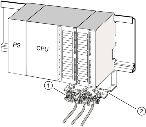
Number Description ① Shielding terminals ② Bracket
Mount the bracket (order number 6ES7390-5AA0-0AA0) to the rail using the two screw bolts. If you use a shield connection element, the dimension specifications apply from the lower edge of the shield connection element.
- Width of the shield connection element: 80 mm
- Number of shielding terminals you can install per shield connection element: max. 4
Table 4- 3 Shielding terminals - Overview \begin{tabular}{|l|l|} \hline Cable with shielding diameter & Shielding terminal order number \ \hline Cable with 2 mm to 6 mm shielding diameter & 6ES7390-5AB00-0AA0 \ \hline Cable with 3 mm to 8 mm shielding diameter & 6ES7390-5BA00-0AA0 \ \hline Cable with 4 mm to 13 mm shielding diameter & 6ES7390-5CA00-0AA0 \ \hline \end{tabular}
33
Configuring 4.4 Specified clearances
4.4 Specified clearances
You must maintain the clearance shown in the figure in order to provide sufficient space for installing the modules, and to allow the dissipation of heat generated by the modules.
The S7-300 assembly on multiple racks shown in the figure below shows the clearance between racks and adjacent components, cable ducts, cabinet walls etc.
For example, when routing your module wiring through cable duct, the minimum clearance between the bottom edge of the shield connection element and the cable duct is 40 mm.
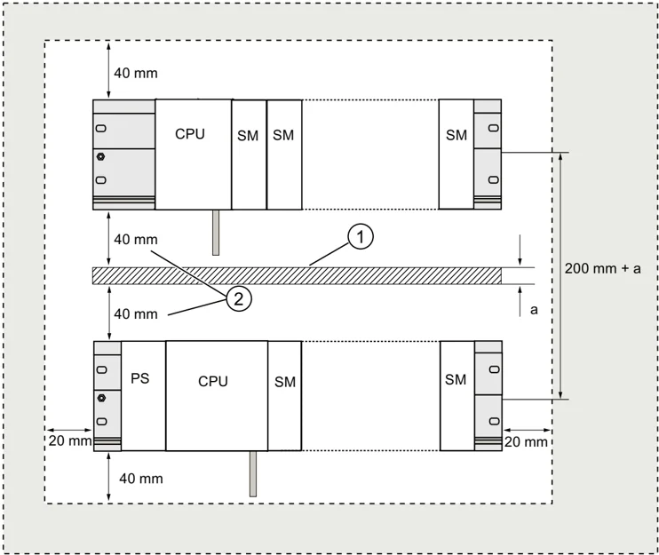
Number Description ① Wiring with cable duct ② Minimum clearance between the cable duct and the bottom edge of the shield connection element is 40 mm.
34
4.5 Arrangement of modules on a single rack
Reasons for using one or multiple racks
The number of racks you need will depend on your application.
| Reasons for using a single rack | Reasons for distributing modules between several racks |
|---|---|
| • Compact, space-saving use of all your modules• Local use of all modules• Fewer signals to be processed | • More signals to be processed• Insufficient number of slots |
Note
If you opt for the installation on a single rack, insert a dummy module to the right of the CPU (order no.: 6ES7370-0AA01-0AA0). This gives you the option of adding a second rack for your application if this is necessary later, simply by replacing the dummy module with an interface module, without having to reinstall and rewire the first rack.
Rules: Layout of modules on a single module rack
The following rules apply to module installations on a single rack:
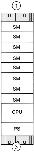
- No more than eight modules (SM, FM, CP) may be installed to the right of the CPU.
- The accumulated power consumption of modules mounted on a rack may not exceed 1.2 A on the S7-300 backplane bus.
Reference
Additional information is available in the technical data, for example, in the SIMATIC S7-300 Automation Systems Manual, Module data, or in the S7-300 Manual, CPU 31xC and CPU 31x, Technical Data.
Example
The figure below shows a layout with eight signal modules in an S7-300 assembly.
35
Configuring 4.6 Distribution of modules to several racks
4.6 Distribution of modules to several racks
Exceptions With CPU 312 and CPU 312C, only a single-row configuration on a rack is possible.
Using interface modules If you are planning an assembly in multiple racks, then you will need interface modules (IM). An interface module routes the backplane bus of an S7-300 to the next rack. The CPU is always located on rack 0.
Table 4- 4 Interface modules - Overview
\begin{tabular}{|l|l|l|} \hline Properties & Two or more rows & Cost-effective 2-row configuration \ \hline Send IM in rack 0 & IM 360 \newline order no.: 6ES7360-3AA01-0AA0 & IM 365 \newline order no.: 6ES7365-0AB01-0AA0 \ \hline Receiver IM in racks 1 to 3 & IM 361 \newline order no.: 6ES7361-3CA01-0AA0 & IM 365 \newline (hard-wired to send IM 365) \ \hline Maximum number of expansion modules & 3 & 1 \ \hline Length of connecting cables & 1 m (6ES7368-3BB01-0AA0) \newline 2.5 m (6ES7368-3BC51-0AA0) \newline 5 m (6ES7368-3BF01-0AA0) \newline 10 m (6ES7368-3CB01-0AA0) & 1 m (hard-wired) \ \hline Comments & - & Rack 1 can only receive signal modules; the accumulated current load is limited to 1.2 A, whereby the maximum for rack 1 is 0.8 A. These restrictions do not apply to operation with interface modules IM 360/IM 361 \ \hline \end{tabular}
Rules: Distribution of modules to several racks Please note the following points if you wish to arrange your modules on multiple racks:
- The interface module always uses slot 3 (slot 1: power supply module; slot 2: CPU, slot 3: Interface module)
- It is always on the left before the first signal module.
- No more than 8 modules (SM, FM, CP) are permitted per rack.
- The number of modules (SM, FM, CP) is limited by the permitted current consumption on the S7-300 backplane bus. The cumulative current consumption of 1.2 A in row 0 (CPU) and 0.8 A each in the expansion rows 1 to 3 must not be exceeded.
Note The current consumption of specific modules is listed in the SIMATIC S7-300 Automation Systems Manual, Module data.
36
Configuring 4.6 Distribution of modules to several racks
Rules: Interference-proof interfacing
Special shielding and grounding measures are not required if you interconnect the CU and EM using suitable interface modules (Send IM and Receive IM).
However, you must ensure
- a low impedance interconnection of all racks,
- that the racks of a grounded assembly are grounded in a star pattern,
- that the contact springs on the racks are clean and not bent, thus ensuring that interference currents are properly discharged to ground.
37
Configuring 4.6 Distribution of modules to several racks
Example: Full assembly using four racks
The figure shows the arrangement of modules in an S7-300 assembly on 4 racks.
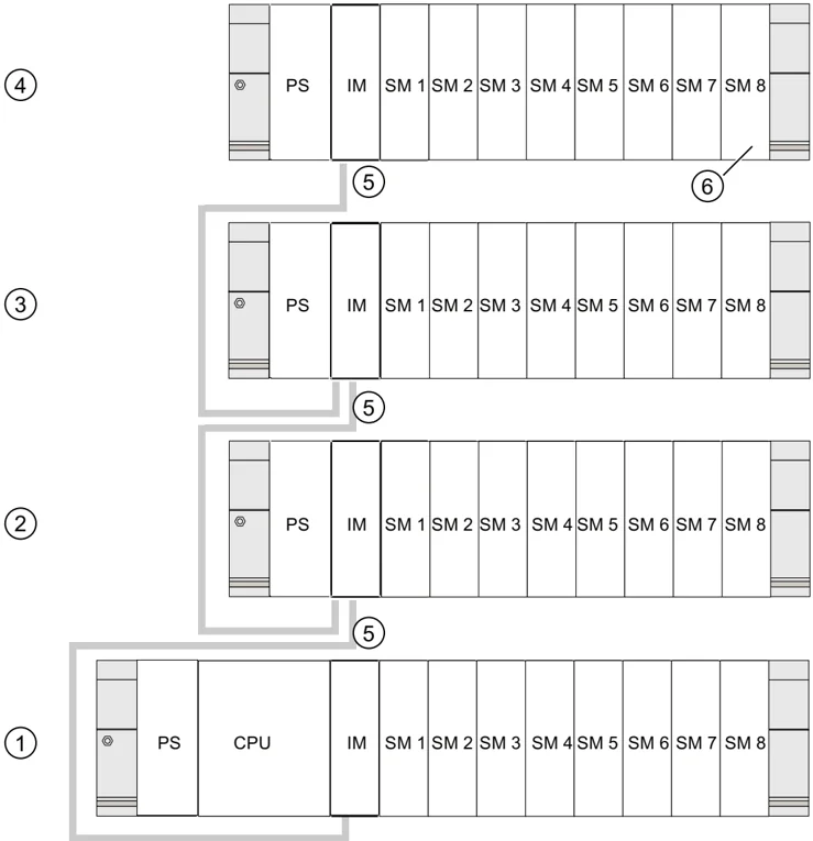
Number Description ① Rack 0 (central unit) ② Rack 1 (expansion module) ③ Rack 2 (expansion module) ④ Rack 3 (expansion module) ⑤ Connection line 368 ⑥ Limitation for CPU 31xC When this CPU is used, do not insert signal module 8 into Rack 4.
38
Configuring 4.7 Selection and installation of cabinets
4.7 Selection and installation of cabinets
Reasons for installing an S7-300 in a cabinet
Your S7-300 should be installed in a cabinet,
- if you plan a larger system,
- if you are using your S7-300 systems in an environment subject to interference or contamination, and
- to meet UL/CSA requirements for cabinet installation.
Selecting and dimensioning cabinets
Take the following criteria into account:
- ambient conditions at the cabinet's place of installation
- the specified mounting clearance for racks (mounting rails)
- accumulated power loss of all components in the cabinet.
The ambient conditions (temperature, humidity, dust, chemical influence, explosion hazard) at the cabinet's place of installation determine the degree of protection (IP xx) required for the cabinet.
Reference for degrees of protection
For additional information on the degrees of protection, refer to IEC 60529 and DIN 40050.
The power dissipation capability of cabinets
The power dissipation capability of a cabinet depends on its type, ambient temperature and on the internal arrangement of devices.
Reference for power loss
For detailed information on dissipatable power loss, refer to the Siemens catalogs. You can find these at: https://mall.automation.siemens.com/de/guest/guiRegionSelector.asp (https://mall.automation.siemens.com/de/guest/guiRegionSelector.asp)
39
Configuring
4.7 Selection and installation of cabinets
Specification of cabinet dimensions
Note the following specifications when you determine the dimensions of a cabinet for your S7-300 installation:
- Space required for racks (mounting rails)
- Minimum clearance between the racks and cabinet walls
- Minimum clearance between the racks
- Space required for cable ducts or fan assemblies
- Position of the stays

Reference for ambient temperatures
For information on permitted ambient temperatures, refer to the S7-300 Automation System, Module Data Manual.
Overview of typical cabinet types
The table below gives you an overview of commonly used cabinet types. It shows you the applied principle of heat dissipation, the calculated maximum power loss and the degree of protection.
Table 4-5 Cabinet types
| Open cabinets | Closed cabinets | |||
|---|---|---|---|---|
| Through-ventilation by natural convection | Increased through-ventilation | Natural convection | Forced convection with rack fan, improvement of natural convection | Forced convection with heat exchanger, internal and external auxiliary ventilation |
40
4.8 Example: Selecting a cabinet
Introduction
The sample below clearly shows the maximum permitted ambient temperature at a specific power loss for different cabinet designs.
Installation
The following device configuration should be installed in a cabinet:
- Central unit, 150 W
- Expansion modules, each with 150 W
- Load power supply under full load, 200 W
This results in an accumulated power loss of 650 W.
| Open cabinets | Closed cabinets | |||
|---|---|---|---|---|
| Mainly inherent heat dissipation, with a small portion across the cabinet wall. | Higher heat dissipation with increased air movement. | Heat dissipation only across the cabinet wall; only low power losses permitted. In most cases, the heat accumulates at the top of the cabinet interior. | Heat dissipation only across the cabinet wall. Forced convection of the interior air improves heat dissipation and prevents heat accumulation. | Heat dissipation by heat exchange between heated internal air and cool external air. The increased surface of the pleated profile of the heat exchanger wall and forced convection of internal and external air provide good heat dissipation. |
| Degree of protection IP 20 | Degree of protection IP 20 | Degree of protection IP 54 | Degree of protection IP 54 | Degree of protection IP 54 |
| Typical power dissipation under following marginal conditions: | ||||
| • Cabinet size: 600 mm x 600 mm x 2,200 mm• Difference between the outer and inner temperature of the cabinet is 20 °C (for other temperature differences refer to the temperature charts of the cabinet manufacturer) | ||||
| up to 700 W | up to 2,700 W (with fine filter up to 1,400 W) | up to 260 W | up to 360 W | up to 1,700 W |
41
Configuring
4.8 Example: Selecting a cabinet
Power loss dissipated
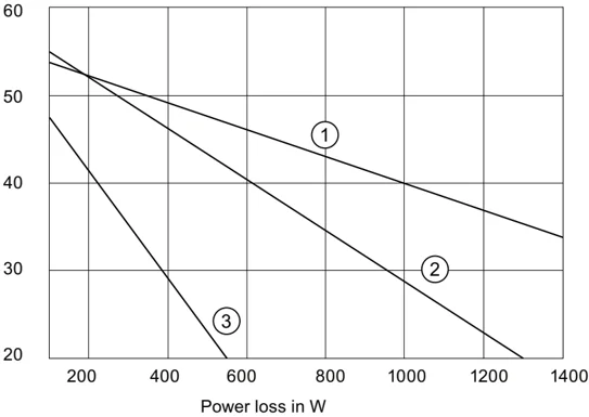
The diagram in the figure below shows guide values for the permitted ambient temperature of a cabinet with the dimensions 600 mm x 600 mm x 2000 mm, based on the accumulated power loss. These values only apply if you maintain the specified assembly and clearance dimensions for racks (rails).
Ambient temperature in °C
| Number | Description |
|---|---|
| ① | Closed cabinet with heat exchanger (heat exchanger size 11/6 (920 x 460 x 111 mm)) |
| ② | Cabinet with through-ventilation by natural convection |
| ③ | Closed cabinet with natural convection and forced convection by equipment fans |
Result
The figure below shows the resultant ambient temperatures, based on an accumulated power loss of 650 W:
Table 4-6 Cabinet selection
| Cabinet design | Maximum permitted ambient temperature |
|---|---|
| Closed with natural convection and forced convection (trend 3) | Operation not possible |
| Open with through-ventilation (trend 2) | approx. 38 °C |
| Closed with heat exchanger (trend 1) | approx. 45 °C |
Cabinet types suitable for horizontal installation of the S7-300:
- open, with closed ventilation
- closed, with heat exchanger
Configuring 4.9 Electrical assembly, protective measures and grounding
4.9 Electrical assembly, protective measures and grounding
4.9.1 Grounding concept and overall structure
This section contains information about the overall configuration of an S7-300 connected to a grounded TN-S network:
- Circuit-breaking devices, short-circuit and overload protection to VDE 0100 and VDE 0113
- Load power supplies and load circuits
- Grounding concept
Note An S7-300 can be used in many different ways, so we can only describe the basic rules for the electrical installation in this document. Those basic rules are a must in order to achieve a fully functional S7-300 system.
Definition: Grounded mains In a grounded mains network, the neutral conductor is always bonded to ground. A short-circuit to ground of a live conductor, or of a grounded part of the system, trips the protective devices.
Specified components and protective measures A number of components and protective measures are prescribed for plant installations. The type of components and the degree of compulsion pertaining to the protective measures will depend on the VDE specification applicable to your particular plant.
The table below shows components and protective measures.
Table 4-7 VDE specifications for the installation of a PLC system
\begin{tabular}{|p{0.35\textwidth}|c|p{0.25\textwidth}|p{0.25\textwidth}|} \hline Compare ... & 1) & VDE 0100 & VDE 0113 \ \hline Disconnect devices for control systems, signal generators and final control elements & (1) & ... Part 460: Master switch & ... Part 1: Load disconnect switch \ \hline Short-circuit / overload protection: In groups for signal generators and final control elements & (2) & ... Part 725: Single-pole fusing of circuits & ... Part 1: \newline \bullet With grounded secondary power circuit: single-pole fusing \newline \bullet Otherwise: fusing of all poles \ \hline Load power supply for AC load circuits with more than five electromagnetic devices & (3) & Galvanic isolation by transformer recommended & Galvanic isolation by transformer mandatory \ \hline \end{tabular}
- This column refers to the numbers in the figure in the chapter "Overview: Grounding".
43
Configuring 4.9 Electrical assembly, protective measures and grounding
Reference For additional information on protective measures, refer to the Appendix.
See also Overview: Grounding (Page 52)
4.9.2 Installing an S7-300 with grounded reference potential
Introduction When the S7-300 is configured with a grounded reference potential, any interference currents are discharged to the grounding conductor / ground. A grounding slide contact is used for this except with CPU 31xC.
Note Your CPU is supplied with grounded reference potential. Therefore, if you wish to install an S7-300 with grounded reference potential, you do not need to modify your CPU!
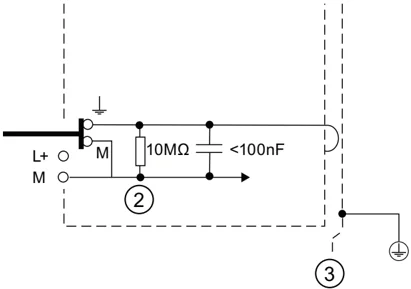
Grounded reference potential of the CPU 31x The figure shows an S7-300 configuration with grounded reference potential (factory state.)
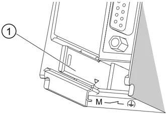
Number Description ① Grounding slide contact in grounded state ② Ground potential of the internal CPU circuitry ③ Mounting rail
Note Do not pull out the grounding slide contact when you install an S7-300 with grounded reference potential.
44
4.9.3 Installing an S7-300 with ungrounded reference potential (not CPU 31xC)
Introduction
When the S7-300 is configured with an ungrounded reference potential, interference currents are discharged to the ground conductor / to ground via an RC combination integrated in the CPU.
Note
An S7-300 with a CPU 31xC cannot be configured ungrounded.
Application
In large systems, the S7-300 may require a configuration with grounded reference potential due to ground-fault monitoring. This is the case, for example, in chemical industry and power stations.
Ungrounded reference potential of the CPU 31x
The figure demonstrates how to achieve a reference potential without grounding in an S7-300 installation.
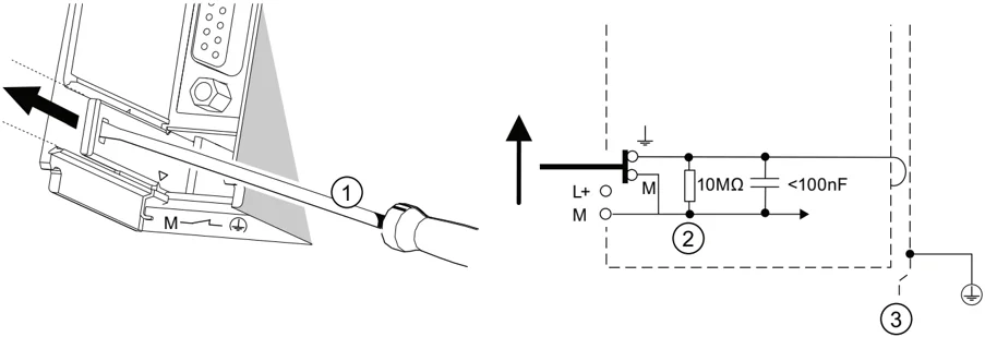
| Number | Description |
|---|---|
| ① | Creating an ungrounded reference potential in your CPUUse a screwdriver with 3.5 mm blade width to push the grounding slide contact forwards in the direction of the arrow until it snaps into place. |
| ② | Ground potential of the internal CPU circuitry |
| ③ | Mounting rail |
Note
You should set up the ungrounded reference potential before you mount the device on the rail. If you have already installed and wired up the CPU, you may have to disconnect the MPI interface before you pull out the grounding slide contact.
45
Configuring 4.9 Electrical assembly, protective measures and grounding
4.9.4 Isolated or non-isolated modules?
Isolated modules Isolated modules are installed with galvanic isolation between the reference potentials of the control circuit (Minternal) and load circuit (Mexternal).
Field of application Use isolated modules for:
- All AC load circuits
- DC load circuits with separate reference potential
Examples: – DC load circuits containing sensors which are connected to different reference potentials (for example, if grounded sensors are located at a considerable distance from the control system and equipotential bonding is not possible). – DC load circuits with grounded positive pole (L+) (battery circuits).
Isolated modules and grounding concept You can always use isolated modules, irrespective of the grounding state of the control system's reference potential.
46