Configuring
4.11 Planning subnets
Example: Installation of a PROFIBUS subnet
The figure below shows you the basic principles of a PROFIBUS subnet installation.
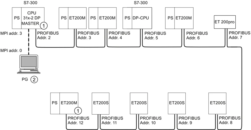
Number Description ① Terminating resistor enabled ② PG connected by means of stub cable for maintenance purposes
71
Configuring
4.11 Planning subnets
Example: CPU 314C-2 DP as MPI and PROFIBUS node
The figure below shows you an assembly with a CPU 314C-2 DP integrated in an MPI subnet and also operated as DP master in a PROFIBUS subnet.
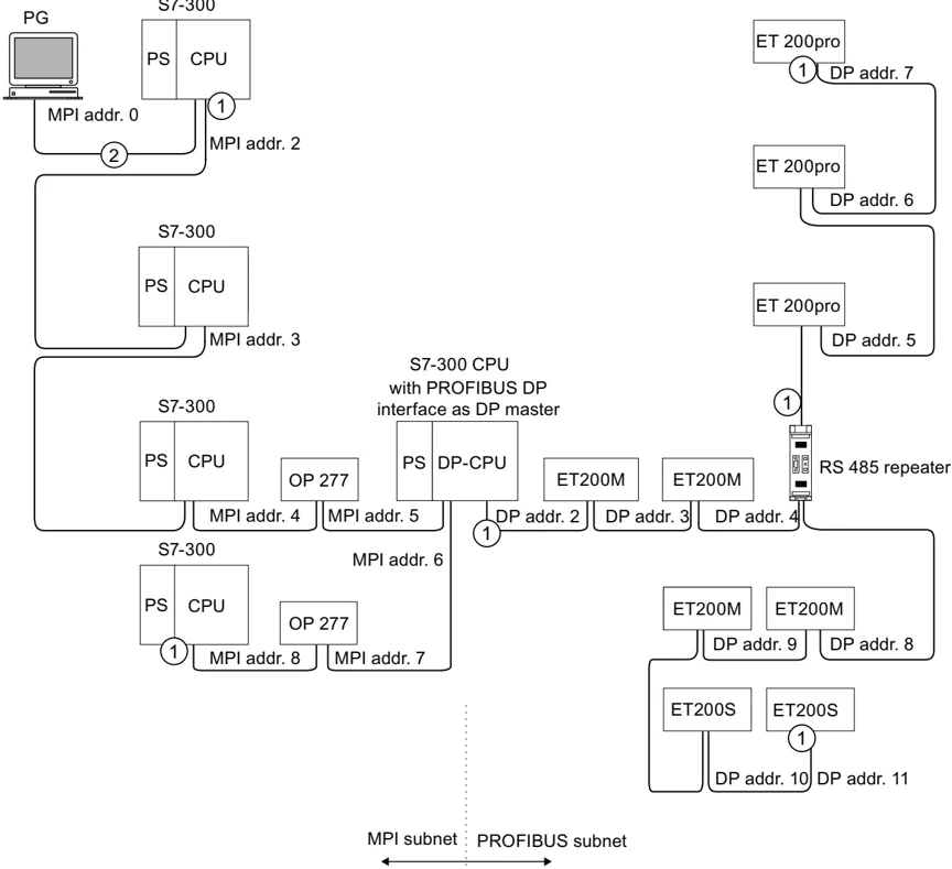
Number Description ① Terminating resistor enabled ② PG connected via a stub cable for maintenance or commissioning purposes
72
Configuring 4.11 Planning subnets
4.11.3 Configuring PROFINET subnets
4.11.3.1 Overview
The next section contains all the information you require to configure PROFINET subnets:
Contents
- PROFINET devices
- Integration of field bus system into PROFINET
- PROFINET IO and PROFINET CBA (Component-Based Automation)
- PROFINET cable lengths
- Ethernet bus cable and connector
- Example of a PROFINET subnet
- Example of a PROFINET IO system
4.11.3.2 PROFINET devices
Definition: Devices in the PROFINET environment
Within the context of PROFINET, "device" is the generic term for:
- Automation systems (e.g. PLC, PC)
- Field devices (for example, PLC, PC, hydraulic devices, pneumatic devices)
- Active network components (for example, switches, gateways, routers)
- PROFIBUS or other fieldbus systems
The main characteristic of a device is its integration into PROFINET communication by means of Ethernet or PROFIBUS.
The following device types are distinguished based on their attachment to the bus:
- PROFINET devices
- PROFIBUS devices
Definition: PROFINET devices
A PROFINET device always has at least one Industrial Ethernet port. A PROFINET device can also be operated as proxy to act as representative that safeguards Ethernet communication between PROFIBUS devices (PROFIBUS slaves connected to an existing PROFIBUS interface) and additional PROFINET devices on the Ethernet.
73
Configuring 4.11 Planning subnets
Definition: PROFIBUS devices
A PROFIBUS device has at least one PROFIBUS link with an electric interface (RS485) or an optical interface (polymer optical fiber, POF).
A PROFIBUS device cannot take part directly in PROFINET communication, but must be implemented by means of PROFIBUS master with PROFINET link or Industrial Ethernet/PROFIBUS link (IE/PB Link) with proxy functionality.
74
Configuring 4.11 Planning subnets
Comparison of the terminology in PROFIBUS DP and PROFINET IO
The following schematic shows you the general names of the most important devices in PROFINET IO and PROFIBUS DP. The table below shows the designation of the various components in the PROFINET IO and PROFIBUS DP context.
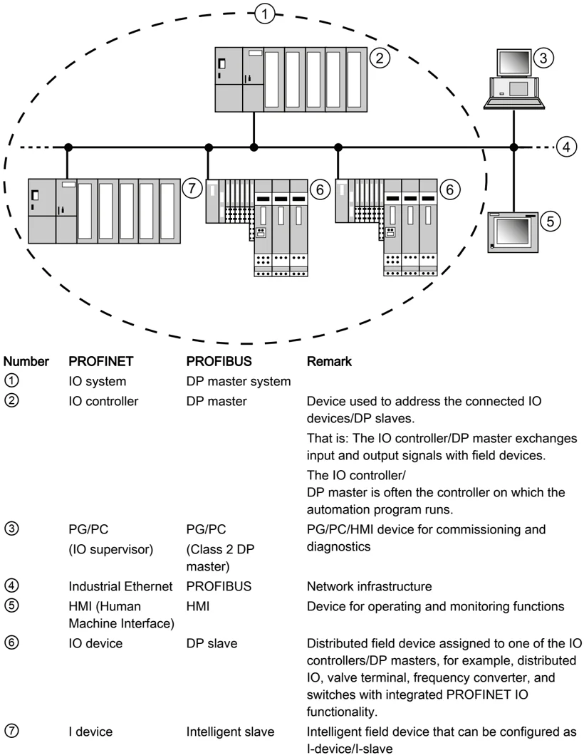
| Number | PROFINET | PROFIBUS | Remark |
|---|---|---|---|
| ① | IO system | DP master system | Device used to address the connected IO devices/DP slaves. |
| ② | IO controller | DP master | That is: The IO controller/DP master exchanges input and output signals with field devices. The IO controller/ DP master is often the controller on which the automation program runs. |
| ③ | PG/PC (IO supervisor) | PG/PC (Class 2 DP master) | PG/PC/HMI device for commissioning and diagnostics |
| ④ | Industrial Ethernet | PROFIBUS | Network infrastructure |
| ⑤ | HMI (Human Machine Interface) | HMI | Device for operating and monitoring functions |
| ⑥ | IO device | DP slave | Distributed field device assigned to one of the IO controllers/DP masters, for example, distributed IO, valve terminal, frequency converter, and switches with integrated PROFINET IO functionality. |
| ⑦ | I device | Intelligent slave | Intelligent field device that can be configured as I-device/I-slave |
Figure 4-3 PROFINET and PROFIBUS devices
75
Configuring 4.11 Planning subnets
Slots and Submodules
A PROFINET IO device is modularly structured - similar to a PROFIBUS DP slave. In doing so, modules are fitted to slots and submodules to subslots. Channels are located on the modules / submodules using which process signals can be read in and issued. The following graphic illustrates the situation.
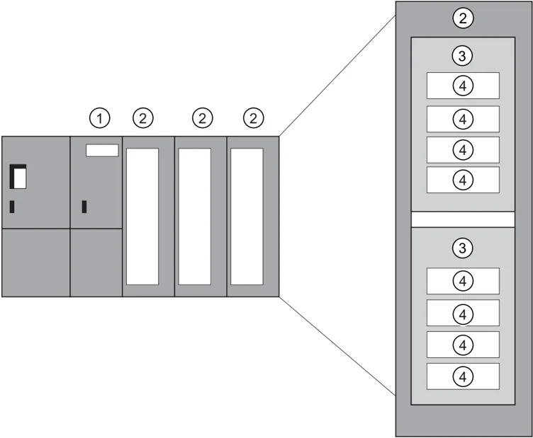
Figure 4-4 Module, Submodule, Slot, and Channel
Number Description ① Interface module ② Module with components ③ Submodule ④ Channel
In principle it is possible to divide a slot into additional subslots on which the submodules are connected.
76
Configuring 4.11 Planning subnets
4.11.3.3 Integration of fieldbuses into PROFINET
Fieldbus integration
PROFINET allows you to use a proxy to integrate existing fieldbus systems (for example, PROFIBUS, ASI) into PROFINET. In this way, you can set up hybrid systems consisting of fieldbus and Ethernet-based subsystems. A continuous technological transition to PROFINET is thus possible.
Interconnecting PROFINET and PROFIBUS
You can interconnect PROFIBUS devices to the local PROFIBUS interface of a PROFINET device. This allows you to integrate existing PROFIBUS configurations in PROFINET.
The following picture illustrates the network types that are supported for PROFINET:
- Industrial Ethernet and
- PROFIBUS.
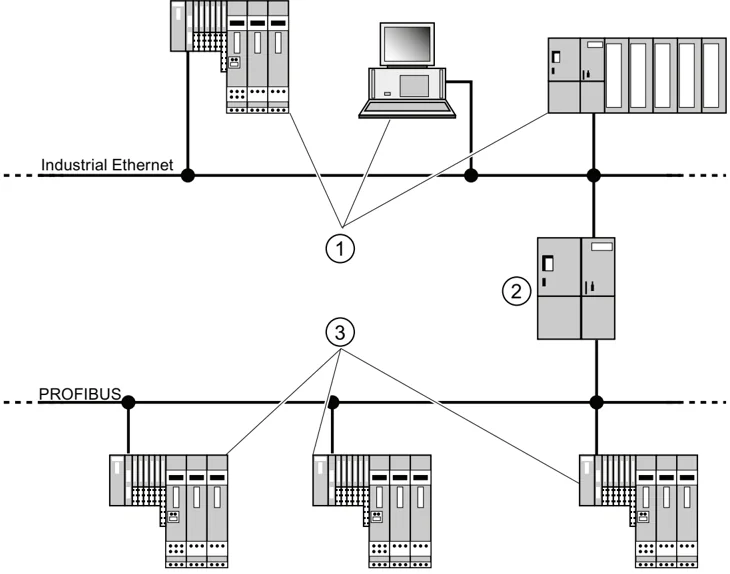
① PROFINET devices ② PROFINET devices with proxy functionality ③ PROFIBUS devices
77
Configuring 4.11 Planning subnets
PROFINET device with proxy functionality = substitute
The PROFINET device with proxy functionality is the substitute for a PROFIBUS device on Ethernet. The proxy functionality allows a PROFIBUS device to communicate not only with its master but also with all nodes on PROFINET.
With PROFINET, existing PROFIBUS systems can be integrated into the PROFINET communication with the aid of an IE/PB link, for example. The IE/PB link then handles communication via PROFINET on behalf of the PROFIBUS components.
In this way, you can link both DPV0 and DPV1 slaves to PROFINET.
Additional information
For information on the differences and common features of PROFINET IO and PROFIBUS DP and information on migrating from PROFIBUS DP to PROFIBUS IO, refer to the From PROFIBUS DP to PROFINET IO programming manual.
4.11.3.4 PROFINET IO and PROFINET CBA
What is PROFINET IO?
As part of PROFINET, PROFINET IO is a communication concept that is used to implement modular, distributed applications.
PROFINET IO allows you to create automation solutions, which are familiar to you from PROFIBUS.
PROFINET IO is implemented using the PROFINET standard for programmable controllers.
The STEP 7 engineering tool helps you to structure and configure an automation solution.
In STEP 7 you have the same application view, regardless of whether you are configuring PROFINET devices or PROFIBUS devices. Program your user program in the same way for both PROFINET IO and PROFIBUS DP, since you will use the extended blocks and system status lists for PROFINET IO.
Reference
Information on new and modified blocks and system status lists can be found in the From PROFIBUS DP to PROFINET IO programming manual.
78
Configuring 4.11 Planning subnets
What is PROFINET CBA?
As part of PROFINET, PROFINET CBA (Component Based Automation) is an automation concept that focuses on the following:
• Implementation of modular applications
• Machine - machine communication
PROFINET CBA lets you create distributed automation solutions, based on default components and partial solutions. This concept meets the demand for a greater modularity in the field of mechanical and systems engineering by extensive distribution of intelligent processes.
With Component Based Automation you can implement complete technological modules as standardized components that can be used in large systems.
You create the modular, intelligent components of the PROFINET CBA in an engineering tool (which may differ according to the device manufacturer). Components that are formed from SIMATIC devices are created with STEP 7, and are interconnected using the SIMATIC iMAP tool.
79
Configuring 4.11 Planning subnets
I nteraction between PROFINET IO and PROFINET CBA
PROFINET CBA is used to integrate PROFINET IO systems into machine-to-machine communication. A PROFINET component is created from a PROFINET IO system in STEP 7, for example. With SIMATIC iMap, you can configure systems consisting of several such components. The communication connections between the devices are configured simply as interconnection lines.
The following graphic illustrates a distributed automation solution with several components which communicate via PROFINET. The components on the right have IO devices and an IO controller on PROFINET IO.
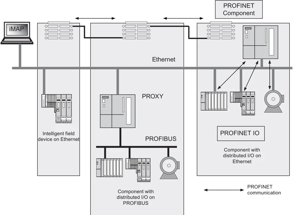
Figure 4-5 PROFINET CBA - modular concept
80
Configuring 4.11 Planning subnets
Extent of PROFINET CBA and PROFINET IO
PROFINET IO and CBA represent two different views of automation devices on Industrial Ethernet.
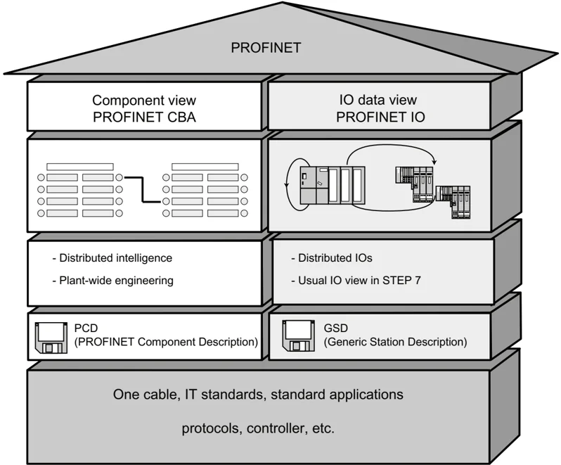
Figure 4-6 Extent of PROFINET CBA and PROFINET IO
Component Based Automation divides the entire system into various functions. These functions are configured and programmed.
PROFINET IO provides an image of the system that is very similar to the view obtained in PROFIBUS. You continue to configure and program the individual automation devices.
81
Configuring
4.11 Planning subnets
Controllers in PROFINET IO and PROFINET CBA
You can also use some PROFINET IO controllers for PROFINET CBA.
The following PROFINET devices can act as a PROFINET CBA and IO controller:
- Programmable logic controllers,
- S7-300 CPU 31x-2 PN/DP, firmware version V2.3 or later
- S7-300 CPU 314C-2 PN/DP, firmware version V3.3 or later
- S7-300 CPU 319-3 PN/DP, firmware version V2.4.0 or later
- CP 343-1 - as of version 6GK7343-1EX21-0XE0 and 6GK7343-1GX21-0XE0
- CP 443-1 Advanced with MLFB 6GK7443-1EX40 as of version V2.1 and 6GK7443-1EX41 as of version V1.0.
The following PROFINET devices can only act as a PROFINET IO controller:
- PCs that are linked to a PROFINET IO-compatible CP (CP 1616 for example) or via SOFTNET PN IO (with CP 1612 for example). With the CP 1616 and SOFTNET PN IO, the user program runs in the CPU of the PC.
- SIMOTION devices for particularly stringent real-time requirements.
Some PROFINET devices can only be used as PROFINET CBA controllers, for example, PCs with standard Ethernet interfaces and the WinLC software.
- CP443-1 EX 40 V2.1 or later or CP443-1 EX41 V 1.0 or later
Proxy in PROFINET IO and PROFINET CBA
The proxies for PROFINET IO and proxies for PROFINET CBA are different.
In PROFINET IO, the proxy for PROFINET IO represents each connected PROFIBUS DP slave as a PROFINET IO device on the PROFINET.
In PROFINET CBA, the proxy for PROFINET CBA represents every connected PROFIBUS DP slave as one component, which can participate in PROFINET communication.
There are thus different IE/PB links for PROFINET IO and PROFINET CBA, for example. At present, you can only use a CPU 31x PN/DP as a proxy for PROFINET CBA.
Linking PROFIBUS devices via an IE/PB link
Please note that proxy functionality is available in both PROFINET IO and PROFINET CBA. For the IE/PB link, this means that you must use different devices depending on the system you are using.
Configuring and integrating components and devices in PROFINET communication
In component based automation, an interconnection editor is used to incorporate the components (SIMATIC iMap, for example). The components are described in a PCD file.
With PROFINET IO, the devices are incorporated using an engineering system (STEP 7, for example). The devices are described in a GSD file.
82
Configuring 4.11 Planning subnets
Interaction between PROFINET CBA and PROFINET IO
PROFINET IO integrates field devices (IO devices) into PROFINET. The input and output data of the IO devices are processed in the user program. The IO devices with their IO controller can, in turn, be part of a component in a distributed automation structure.
Communication between a CPU as the IO controller and the assigned IO devices as PROFINET IOs is configured in the same way as for a PROFIBUS DP master system in STEP 7. The user program is also created in STEP 7. From the entire PN IO system, you create a component in STEP 7 (see Figure PROFINET CBA).
You then configure communication between the components in user-friendly SIMATIC iMAP.
Update time
The IO controller (outputs) provides new data to all IO devices in the PROFINET IO system within the update time. This means that all the IO devices have sent their latest data to the IO controller (inputs).
Note Send Cycles for Cyclical Data Exchange
STEP 7 determines the update time on the basis of the existing hardware configuration and the resulting cyclical data traffic. During this time, a PROFINET IO device has exchanged its user data with the associated IO controller.
You can set the update date either for a whole bus segment of an IO controller, or for an individual IO device.
In STEP 7, the update time can be changed manually.
The smallest possible update time in a PROFINET system depends on the following factors:
- Number of PROFINET IO devices
- Quantity of configured user data
- PROFINET IO communication allocation (compared to PROFINET CBA communication allocation)
Additional cyclical PROFINET services
The update time dialog in STEP 7/HW Config is used to set an update date for the device to be reserved for PROFINET IO.
See the STEP 7 Online Help for more information.
83
Configuring
4.11 Planning subnets
Send cycle
Period between two successive intervals for IRT or RT communication. The send cycle is the shortest possible transmit interval for exchanging data. The calculated update times are multiples of the send cycle.
The minimum possible update time thus depends on the minimum send cycle of the IO controller that can be set.
If both the IO controller and the IO device support a send cycle of 250 µs, you can achieve a minimum update time of 250 µs.
It is also possible to operate IO devices that only support a send cycle of 1 ms on an IO controller that works with a send cycle of 250 µs. The minimum update time for the IO devices concerned is then at least 1 ms, however.
Update times for CPU 31x PN/DP
The following update times can be parameterized:
| Real-time communication | Send cycle | Update time |
|---|---|---|
| With RT: | 250 µs | ⇒ 250 µs to 128 ms |
| 500 µs | ⇒ 500 µs to 256 ms | |
| 1 ms | ⇒ 1 ms to 512 ms | |
| 2 ms | ⇒ 2 ms to 512 ms | |
| 4 ms | ⇒ 4 ms to 512 ms | |
| For IRT with the "high flexibility" option: | 250 µs | ⇒ 250 µs to 128 ms |
| 500 µs | ⇒ 500 µs to 256 ms | |
| 1 ms | ⇒ 1 ms to 512 ms | |
| For IRT with the "high performance" option: | 250 µs | ⇒ 250 µs to 4 ms |
| 500 µs | ⇒ 500 µs to 8 ms | |
| 1 ms | ⇒ 1 ms to 16 ms | |
| 2 ms | ⇒ 2 ms to 32 ms | |
| 4 ms | ⇒ 4 ms to 64 ms |
The minimum update time is determined by the number of devices used, by the volume of configured user data, and by the time slice for PROFINET IO communication. STEP 7 automatically considers these dependencies during configuration.
Configuring 4.11 Planning subnets
Send cycles with odd values for IRT with the "high performance" option:
In addition to the "even value" send cycles (250 µs, 500 µs, 1 ms, 2 ms, 4 ms) in the range from 250 µs to 4 ms, you can set up any multiple of 125 µs as "odd value" send cycle for IRT with the "high performance" option: 375 µs, 625 µs ... 3.875 ms.
Rule for all PROFINET IO devices operating with "odd value" send cycles:
- Update time = send cycle
- It is not possible to complement IRT with the "high performance" through RT devices
Details of the possible uses of the individual products
See also the documentation for the product concerned.
4.11.3.5 PROFINET cable lengths and network expansion
Network expansion options are based on various factors (hardware design used, signal propagation delay, minimum distance between data packets, etc.)
Twisted pair cables
Twisted pair cables are used to interconnect terminal devices with the Industrial Ethernet FC cabling system. It is designed for use in environments with low EMC load, for example, in offices or in control cabinets.
The length of twisted pair cables between two devices may not exceed 10 m.
Compared to Industrial Ethernet twisted pair cables, the twisted pair cables are significantly thinner and more flexible due to the reduced effort for their shielding. The connectors used in connecting industrial twisted pair components are standardized RJ45 connectors and sub D connectors.
85
Configuring
4.11 Planning subnets
Product range
The following twisted pair cables are available:
Table 4-23 Data for ready-made twisted pair cables
| Cable designation | Application | Available lengths | Order number |
|---|---|---|---|
| TP Cord RJ45/RJ45 | TP connecting cable with two RJ45 connectors | 0.5 m1.0 m2.0 m6.0 m10.0 m | 6XV1850-2GE506XV1850-2GH106XV1850-2GH206XV1850-2GH606XV1850-2GN10 |
| TP XP cord RJ45/RJ45 | TP crossover cable with two RJ45 connectors | 0.5 m1.0 m2.0 m6.0 m10.0 m | 6XV1850-2HE506XV1850-2HH106XV1850-2HH206XV1850-2HH606XV1850-2HN10 |
| TP cord 9/RJ45 | TP cable with 9-pin sub-D connector and RJ45 connector | 0.5 m1.0 m2.0 m6.0 m10.0 m | 6XV1850-2JE506XV1850-2JH106XV1850-2JH206XV1850-2JH606XV1850-2JN10 |
| TP XP cord 9/RJ45 | Crossover TP cable with 9-pin sub-D connector and RJ45 connector | 0.5 m1.0 m2.0 m6.0 m10.0 m | 6XV1850-2ME506XV1850-2MH106XV1850-2MH206XV1850-2MH606XV1850-2MN10 |
| TP patch cable 9-45/RJ45 | TP cable with RJ45 connector and sub-D connector, 45° cable exit (for OSM/ESM only) | 1.0 m | 6XV1850-2NH10 |
| TP XP patch cable 9-45/RJ45 | Crossover TP cable with RJ45 connector and sub-D connector with 45° cable exit (for OSM/ESM only) | 1.0 m | 6XV1850-2PH10 |
| TP XP patch cable 9/9 | Crossover TP cable for direct interconnection of two industrial Ethernet network components with ITP interface, with two 9-pin sub-D connectors | 1.0 m | 6XV1850-2RH10 |
| TP cord RJ45/15 | TP cable with 15-pin sub-D connector and RJ45 connector | 0.5 m1.0 m2.0 m6.0 m10.0 m | 6XV1850-2LE506XV1850-2LH106XV1850-2LH206XV1850-2LH606XV1850-2LNN10 |
| TP XP patch cable RJ45/15 | Crossover TP cable with 15-pin sub-D connector and RJ45 connector | 0.5 m1.0 m2.0 m6.0 m10.0 m | 6XV1850-2SE506XV1850-2SH106XV1850-2SH206XV1850-2SH606XV1850-2SN10 |
Operating Instructions, □□/□□□□, A5E00105492-12
Configuring 4.11 Planning subnets
Industrial Ethernet Fast Connect twisted pair cables
The Fast Connect twisted pair cabling system is ideal for structured cabling in the production hall. FastConnect cables allow for the quick and easy on-site assembly of patch cables. The RJ45 cabling technology is the existing standard and is also available as an industrial version which allows structured cabling.
Product range
Industrial Ethernet Fast Connect twisted pair cables available:
Table 4-24 Data for user assemblies using patch cables of the Fast Connect product family
Reference
Detailed information is available in the
- SIMATIC NET Manual: Twisted-pair and fiber-optic networks (6GK1970-1BA10-0AA0)
- Internet under Service & Support (http://www.siemens.com/automation/service&support)
- Catalog IK PI, SIMATIC NET (E86060-K6710-A101-B5)
See also
Connecting the PG to a node (Page 156) Connecting the PG to several nodes (Page 157)
87
Configuring 4.11 Planning subnets
4.11.3.6 Connectors and other components for Ethernet
The selection of the bus cable, bus connector and other components for Ethernet (for example, switches, etc.) depends on the intended application.
We offer a range of products covering a variety of applications for the installation of an Ethernet connection.
Reference
- SIMATIC NET: Twisted-pair and fiber-optic networks (6GK1970-1BA10-0AA0)
4.11.3.7 Example of a PROFINET subnet
Example: Installation of a PROFINET subnet
The graphic illustrates the combination of corporate level and process control level via industrial Ethernet. PCs in a classical office environment can be used to acquire data of the process automation system.
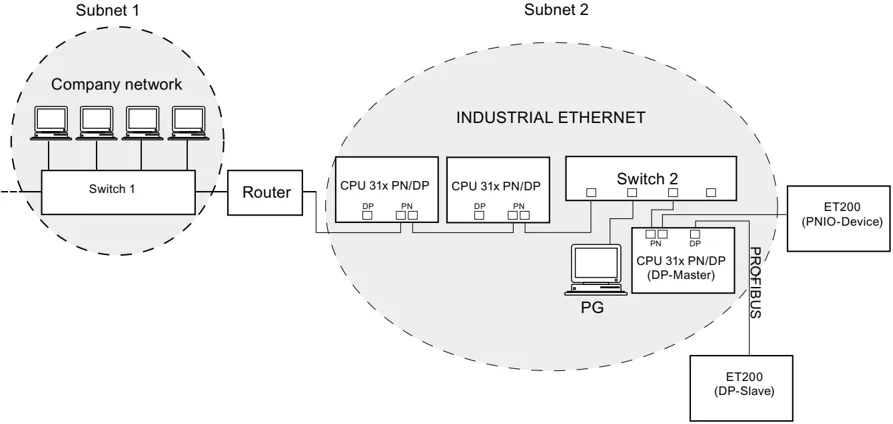
Figure 4-7 Example of a PROFINET subnet
88
Configuring 4.11 Planning subnets
I nstallation guidelines
PROFINET allows you to set up a high-performance and continuous communication system. You can additional increase performance by using the following installation guidelines.
- Interconnect a router between the office network and the PROFINET system. Use the router to define access privileges for your PROFINET system.
- Where practical, set up your PROFINET system in a star architecture (for example, in the control cabinet).
- Keep the number of switches low. This increases clarity of your PROFINET system architecture.
- Connect your programming device (PG) close to the communication partner (for example, programming device and communication partner on the same switch).
- Modules with PROFINET interfaces may only be operated in LANs where all nodes are equipped with SELV/PELV power supplies or protection systems of equal quality.
- A data transfer device that ensures this safety must be specified for the coupling to the WAN.
R eference
For detailed information on Industrial Ethernet networks or network components, refer to:
- the Internet URL http://www.siemens.com/automation/service&support.
- The STEP 7 Online Help. There you can also find additional information on IP address assignment.
- The Communication with SIMATIC (EWA 4NEB 710 6075-01) manual
- In the SIMATIC NET Twisted-Pair and Fiber-Optic Networks (6GK1970-1BA10-0AA0) manual
89