Commissioning 8.5 Commissioning PROFIBUS DP
Commissioning
Commission the DP CPU as a DP slave in the PROFIBUS subnet as follows:
- Switch on power, but hold the CPU in STOP mode.
- First, switch on all other DP masters/slaves.
- Now switch the CPU to RUN mode.
Startup of DP CPU as DP slave
When the DP-CPU is switched to RUN mode, two mutually independent operating mode transitions are executed:
- The CPU switches from STOP to RUN mode.
- The CPU starts data exchange with the DP master via the PROFIBUS DP interface.
Recognizing the Operating State of the DP master (Event Recognition)
The table below shows how the DP CPU operating as a DP slave recognizes operating state transitions or data exchange interruptions.
Table 8-9 Detecting operating mode transitions and station failure of DP CPUs operated as DP master, in the DP CPU as DP slave
Tip:
When commissioning the CPU as DP slave, always program OB82 and OB86. This helps you to recognize and evaluate the respective operating states or data exchange errors.
Commissioning
8.5 Commissioning PROFIBUS DP
Status/modify, programming via PROFIBUS
As an alternative to the MPI interface, you can program the CPU or execute the PG's status and control functions via the PROFIBUS DP interface.
Note
The execution of status and control function via PROFIBUS DP interface extends the DP cycle.
User data transfer by way of transfer memory
The DP CPU operating as intelligent DP slave provides a transfer memory for PROFIBUS DP. User data are always exchanged between the CPU (DP slave) and the DP master by way of this transfer memory. You can configure up to 32 address ranges for this function.
That is, the DP master writes its data to these transfer memory address ranges, the CPU reads these data in the user program, and vice versa.
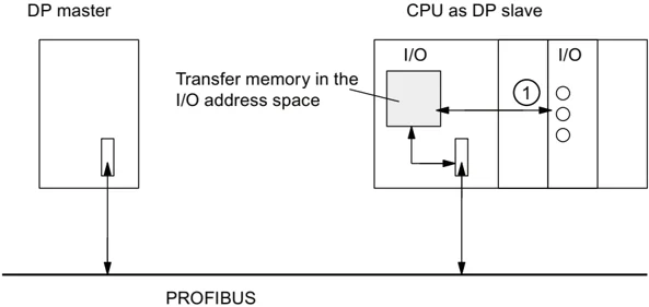
Number Description ① The functions which control data exchange between transfer memory and the distributed I/O of the slave CPU must be implemented in the user program. The DP master cannot access this I/O directly.
174
Commissioning 8.5 Commissioning PROFIBUS DP
Address ranges of transfer memory
In STEP 7, configure the I/O address ranges:
- You can configure up to 32 I/O address ranges.
- The maximum length of this address range is 32 bytes.
- You can configure a maximum of 244 input bytes and 244 output bytes.
The table below shows the principle of address ranges. You can also find this figure in the STEP 7 configuration.
Table 8- 10 Configuration example for the address ranges of transfer memory
175
Commissioning
8.5 Commissioning PROFIBUS DP
Example program
Below, you will see a small example program for data exchange between the DP master and the DP slave. The addresses used in the example are found in the table above.
| In the DP slave CPU | In the DP master CPU |
|---|---|
| L 2 //Data preparation in the //DP slave | |
| T MB 6 | |
| L IB 0 | |
| T MB 7 | |
| L MW 6 //Forward data to //DP master | |
| T PQW 310 | |
| L PIB 222 //continued processing of //received data in DP master | |
| T MB 50 | |
| L PIB 223 | |
| L B#16#3 | |
| + I | |
| T MB 51 | |
| L 10 //Data preparation in the //DP master | |
| + 3 | |
| T MB 60 | |
| CAL SFC 15 //Send data to the DP slave | |
| L LADDR:= W#16#0 | |
| RECORD:=P#M60.0 //In the user program of the masters //a block of 20 bytes length starting at MB60 //is written consistently to the output area //PAB0 to PAB19 //(transfer area from master to //slave) | |
| Byte20 | |
| RET_VAL :=MW 22 | |
| CAL SFC 14 //Receive data from //DP master | |
| LADDR:=W#16#D //In the slave, the //peripheral bytes PEB13 //to PEB32 (data //transferred from master) //are read consistently and //stored in MB30 |
176
Commissioning 8.5 Commissioning PROFIBUS DP
//to MB49 RET_VAL :=MW 20 RECORD:=P#M30.0 byte 20 L MB 30 //Received data //continue processing L MB 7
-
I
T MW 100
Working with transfer memory
Note the following rules when working with the transfer memory:
- Assignment of address ranges: – Input data of DP slaves are always output data of the DP master – Output data of DP slaves are always input data of the DP master
- The user can define these addresses. In the user program, access data with load/transfer instructions or with SFC 14 and SFC 15. You can also define addresses of the process image of inputs or outputs.
- The lowest address of specific address ranges is their respective start address.
- The length, unit and consistency of the address ranges for DP master and DP slave must be identical.
- The master and slave addresses may differ in logically identical transfer memory (independent logical I/O address spaces in the master and slave CPU).
Note Assign addresses from the I/O address range of the DP CPU to the transfer memory. You cannot use any addresses which have been assigned to transfer memory for other I/O modules.
S5 DP master
If you use an IM 308-C as a DP master and the DP CPU as a DP slave, the following applies to the exchange of consistent data.
Use IM 308-C in the S5 control to program FB192 for enabling exchange of consistent data between the DP master and slave. With the FB192, the data of the DP CPU are only output or read out in a consistent block.
S5-95 as DP master
If you set up an AG S5-95 for operation as DP master, you also have to set its bus parameters for the DP CPU as DP slave.
177
Commissioning 8.5 Commissioning PROFIBUS DP
User data transfer in STOP mode
User data is treated in transfer memory according to the STOP state of the DP master or DP slave.
- The DP slave CPU goes into STOP: Data in transfer memory of the CPU is overwritten with "0", that is, the DP master reads "0" in direct data exchange mode.
- The DP master goes into STOP: Current data in transfer memory of the CPU are retained and can be read by the CPU.
PROFIBUS address
For the DP CPU, you must not set "126" as a PROFIBUS address.
See also
User-specific addressing of modules (Page 129)
8.5.4 Direct data exchange
Requirements
STEP 7 V 5.x or higher lets you configure "Direct data exchange" for PROFIBUS nodes. DP CPUs can take part in direct data exchange as senders and receivers.
Definition
"Direct data exchange" is a special communication relationship between PROFIBUS DP nodes.
Characteristic of direct data exchange are the PROFIBUS DP nodes "Listening" on the bus for data a DP slave returns to its DP master. This mechanism allows "Listening stations" (receivers) direct access to modified input data of remote DP slaves.
address ranges
In your STEP 7 configuration of the relevant peripheral input addresses, specify which address range of the receiving node is to receive data requested from the sending node.
The following types of DP-CPU are possible:
- DP slave sending station
- Receiving station, as DP slave or DP master, or as CPU not integrated in a master system.
178
Commissioning
8.5 Commissioning PROFIBUS DP
Example: Direct data exchange via DP CPUs
The example in the figure below shows the relationships you can configure for direct data exchange. In the figure all the DP masters and all the DP slaves that are marked as "CPU" are each a DP CPU.
Note that other DP slaves (ET 200M, ET 200pro, ET 200S) can only operate as sending nodes.
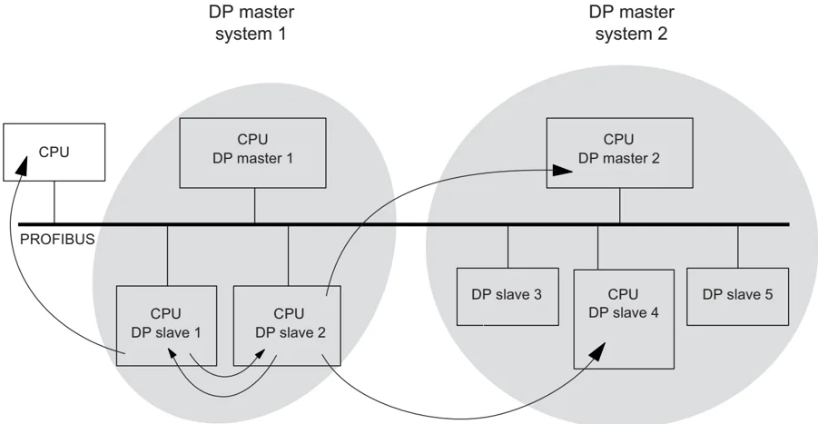
Figure 8-1 Direct data exchange via DP CPUs
179
Commissioning 8.6 Commissioning PROFINET IO
8.6 Commissioning PROFINET IO
8.6.1 Requirements
Requirements
PROFINET IO is supported in STEP 7 V5.3 SP1 or higher. A later version of STEP 7 may be required to support specific CPU functionality. Information about the STEP 7 versions required for specific CPUs is available in the CPU 31xC and CPU 31x, Technical Data Manual.
PROFINET IO address ranges of the CPUs
Table 8- 11 PROFINET IO address ranges of the CPUs
\begin{tabular}{|l|l|l|l|l|} \hline Address range & 314C-2 PN/DP & 315-2 PN/DP & 317-2 PN/DP & 319-3 PN/DP \ \hline Entire address range of inputs and of outputs & 2048 Bytes & 2048 Bytes & 8192 Bytes & 8192 Bytes \ \hline of these in the process image, for inputs and outputs respectively & Max. 2048 bytes & Max. 2048 bytes & Max. 8192 bytes & Max. 8192 bytes \ \hline • Default & 256 Bytes & 128 Bytes & 256 Bytes & 256 Bytes \ \hline \end{tabular}
Diagnostic addresses use 1 byte each in the input address range for
- the IO controller, PROFINET interface and ports
- all I/O devices (PROFINET interface and its ports) and all modules/submodules inside the device
You can use these addresses, for example, to read module-specific diagnostics data records by calling SFB52. STEP 7 assigns diagnostic addresses in descending order, starting at the highest byte address.
Information about the structure of module-specific diagnostics data records is available in the From PROFIBUS DP to PROFINET IO Programming Manual.
180
Commissioning
8.6 Commissioning PROFINET IO
8.6.2 Commissioning the PROFINET IO system
Commissioning requirements:
- The CPU is in STOP mode.
- The IO devices are switched on.
- The PROFINET subnet is installed and the communication nodes (e.g. programming device, IO controller, IO devices) are connected to the PROFINET subnet.
Options of commissioning the PROFINET IO system
There are several ways for you to start with commissioning the PROFINET IO interface of the CPU, and then the PROFINET IO system:
- Online via MPI/ DP interface
- online via the PROFINET interface
- Offline, by saving the data to a Micro Memory Card in SIMATIC Manager on your programming device and then inserting the Micro Memory Card into the CPU
Commissioning a PROFINET IO system via MPI/DP
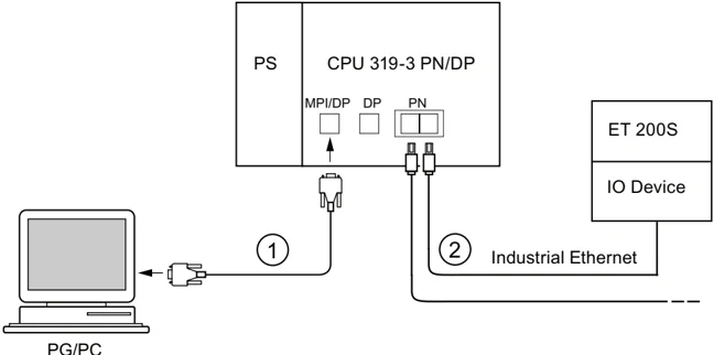
Number Meaning ① Use the PG cable to connect the PG to the integrated MPI/DP interface of the CPU. ② Using a twisted-pair cable, connect the IO device to a port of the PROFINET interface of the CPU. You can connect additional PROFINET devices to the second free port of the PROFINET interface.
Note Usually, you must use an external switch to interconnect CPUs 31x PN/DP without integrated switch (PN interface with single port) with other PROFINET devices.
181
Commissioning 8.6 Commissioning PROFINET IO
Commissioning a PROFINET IO system directly via PROFINET interface
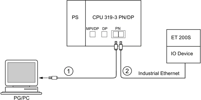
Number Meaning ① Using a preassembled twisted-pair cable, connect the programming device/PC to one of the ports of the PROFINET interface of the CPU. ② Using a twisted-pair cable, connect the IO device to the second available port of the PROFINET interface of the CPU.
8.6.3 Configuring the PROFINET IO system
Configuring the PROFINET IO system
182
Commissioning
8.6 Commissioning PROFINET IO
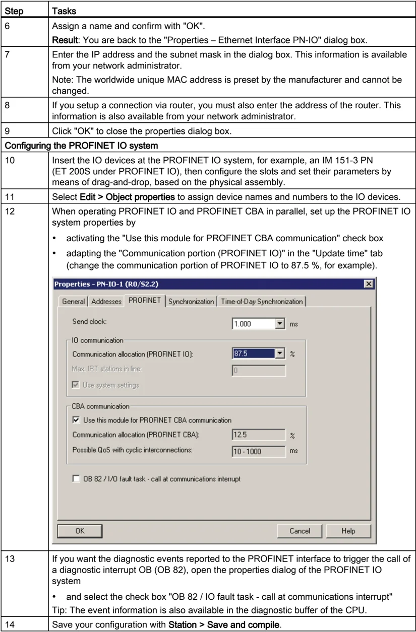
| Step | Tasks |
|---|---|
| 6 | Assign a name and confirm with "OK".Result: You are back to the "Properties – Ethernet Interface PN-IO" dialog box. |
| 7 | Enter the IP address and the subnet mask in the dialog box. This information is available from your network administrator.Note: The worldwide unique MAC address is preset by the manufacturer and cannot be changed. |
| 8 | If you setup a connection via router, you must also enter the address of the router. This information is also available from your network administrator. |
| 9 | Click "OK" to close the properties dialog box. |
| Configuring the PROFINET IO system | |
| 10 | Insert the IO devices at the PROFINET IO system, for example, an IM 151-3 PN (ET 200S under PROFINET IO), then configure the slots and set their parameters by means of drag-and-drop, based on the physical assembly. |
| 11 | Select Edit > Object properties to assign device names and numbers to the IO devices. |
| 12 | When operating PROFINET IO and PROFINET CBA in parallel, set up the PROFINET IO system properties by• activating the "Use this module for PROFINET CBA communication" check box• adapting the "Communication portion (PROFINET IO)" in the "Update time" tab (change the communication portion of PROFINET IO to 87.5 %, for example). |
| 13 | If you want the diagnostic events reported to the PROFINET interface to trigger the call of a diagnostic interrupt OB (OB 82), open the properties dialog of the PROFINET IO system• and select the check box "OB 82 / IO fault task - call at communications interrupt"Tip: The event information is also available in the diagnostic buffer of the CPU. |
| 14 | Save your configuration with Station > Save and compile. |
CPU 31xC and CPU 31x: InstallationOperating Instructions, 03/2011, A5E00105492-12 183
Commissioning
8.6 Commissioning PROFINET IO
| Step | Tasks |
|---|---|
| Configuration Download | |
| 15 | Download the configuration to the CPU. You have three options:• Online via MPI/ DP interface (the PG and CPU must be located in the same subnet). When you download the configuration in a system containing several node addresses, select the appropriate MPI or PROFIBUS address of the destination CPU.• online via the PROFINET interface When you download the configuration in a system containing several nodes, select the appropriate IP address of the destination CPU. The "available users" can be displayed in a download dialog box. If you have not yet assigned an IP address to the CPU, select the MAC address of the target CPU. In the next dialog box, you can assign the configured IP address to the CPU.The PG must be connected to the subnet. The interface of the programming device must be set to TCP/IP (Auto) mode. Setting in the IE-PG Access tab of the interface properties dialog box: Assign project-specific IP address.• Offline, by saving the data to a Micro Memory Card in SIMATIC Manager on your programming device and then inserting the Micro Memory Card into the CPU |
| Assigning IO device names | |
| 16 | Requirement: The programming device must be connected to the subnet. The interface of the programming device must be set to TCP/IP (Auto) mode. Setting in the IE-PG Access tab of the interface properties dialog box: Assign Project-Specific IP Address.Procedure: In online mode, select the various IO devices in HW Config, then select PLC > Ethernet > Assign Device Name to assign the corresponding device names.Note: If you enabled the "Support device replacement without removable medium" function in your parameters and specified the target topology of the PROFINET IO system using the topology editor, you could possibly dispense with the specification of the device name. For this to be the case, the actual topology must correspond with the target topology and the devices must be reset to the factory settings.Note: The CPU can only assign the IP address automatically, and thus enable its correct communication with the IO device, after you assigned a device name to the latter.If the configuration of the IO devices you downloaded to the CPU actually corresponds with their physical configuration on the subnet, the CPU addresses the IO devices, and the BF LED stops flashing both on the CPU and on the IO device.You can now switch the CPU to RUN, provided there are no other conditions preventing a startup, and the CPU and IO devices exchange data (read inputs, write outputs, for example). |
Result
You used STEP 7 to configure the PROFINET interface of your CPU and the and the PROFINET IO system. The CPU can now be reached by other nodes in your Industrial Ethernet subnet.
184
Commissioning
8.6 Commissioning PROFINET IO
Reference
- Additional options for the IP address assignment are described in chapter Assigning IP address parameters and device names (Page 137)
- For more information with regard to the address assignment and settings of the properties for the PROFINET IO interface and the individual ports, refer to the STEP 7 Online Help and to the PROFINET System Description (http://support.automation.siemens.com/WW/view/en/19292127).
CPU startup for operation as IO controller
In its startup sequence, and based on the preset configuration, the CPU verifies the actual configuration
- of the local I/O,
- of the distributed I/O on the PROFIBUS DP system, and
- the PROFINET IO system.
The startup of the CPU is determined by the corresponding configuration in the "Startup" tab:
Table 8- 12 CPU startup for operation as IO controller
\begin{tabular}{|p{0.25\textwidth}|p{0.35\textwidth}|p{0.35\textwidth}|} \hline Preset configuration = actual configuration & \multicolumn{2}{c|}{Preset \neq Actual configuration} \ \cline{2-3} & Startup permitted if the preset configuration does not match the actual configuration & Startup not permitted if the preset configuration does not match the actual configuration \ \hline CPU goes into RUN. & CPU goes into RUN. After POWER ON, and after the parameter monitoring time has expired, the CPU goes into RUN. The flashing of the BF-LED for the PROFINET interface indicates that at least one IO device cannot be addressed. In this case, check whether all IO devices are switched on and correspond to the specified configuration. For additional information, read the diagnostics buffer in STEP 7. & CPU startup fails. \ \hline \end{tabular}
185
Commissioning
8.6 Commissioning PROFINET IO
CPU startup for operation as intelligent device
In its startup sequence, and based on its preset configuration, the CPU verifies the actual configuration
- of the local I/O,
- of the distributed I/O on the PROFIBUS DP system, and
- the PROFINET IO system.
The CPU startup depends on the CPU configuration in the Startup tab:
Table 8-13 CPU startup for operation as intelligent device
| Target configuration = actual configuration | Preset configuration ≠ actual configuration | |
|---|---|---|
| Startup permitted if the preset configuration does not match the actual configuration | Startup not permitted if the preset configuration does not match the actual configuration | |
| CPU goes into RUN. | CPU goes into RUN.The CPU goes into RUN after POWER ON and expiration of the parameter monitoring time.Flashing of the BF-LED for the PROFINET interface means that:- In a configuration as I-device without IO subsystem: None of the higher-level controllers is able to communicate with the I-device (for example, a connection interruption or mismatch of the transfer areas between the IO controller and the I-device). In this situation, check the configuration and wiring of the PROFINET IO system.- In a configuration as I-device with IO subsystem: The higher-level controller is unable to communicate with the I-device (for example, a connection interruption or mismatch of the transfer areas between the IO controller and the I-device).Or:At least one IO device cannot be addressed. In this case, check whether all IO devices are switched on and correspond to the specified configuration.For more information, read the diagnostics buffer in STEP 7. | CPU startup fails. |
186
Commissioning 8.6 Commissioning PROFINET IO
Detecting interruptions in the data transfer to the IO device
The following table shows, how the CPU 31x PN/DP recognizes interruptions of the data transfer:
Table 8- 14 Even recognition of the CPU 31x PN/DP as IO controller
For additional information about this topic and the response to operating mode transitions in the IO controller or I-device, refer to chapter "Intelligent Device" in the PROFINET System Description.
Note
When commissioning the CPU for operation with intelligent devices, always program the OB 83 in the IO controller and intelligent device (because of the return-of-submodule alarms generated during the operating state transition to RUN of the relevant communication partner).
Always program OB86 when you commission the CPU. This allows you to detect and analyze interruptions in the data transfer.
If "OB85 - call up at I/O access error" was configured in HW Config to detect access errors during transfer of the process image, OB85 must also be programmed.
Reference
More detailed information about the user data transfer is found in the PROFINET System Description (http://support.automation.siemens.com/WW/view/en/19292127).
Status/control, programming via PROFINET
As an alternative to the MPI /DP interface, you can program the CPU or execute the PG's status and control functions via the PROFINET interface..
If you have not commissioned the PROFINET interface of the CPU yet, you can connect to the CPU using its MAC address (see also Configuring the PROFINET IO System in the table above).
To do so, use HW Config to download your configuration to the CPU. Address the CPU using its MAC address. The CPU is also assigned the configured IP address after you downloaded the configuration. You can now use all PG functions on the interface, for example, loading the program, monitor/modify, ... .
187
Commissioning 8.6 Commissioning PROFINET IO
188