Configuring
4.11 Planning subnets
4.11.3.8 PROFINET IO System
Functions of PROFINET IO
The following graphic shows the new functions in PROFINET IO:
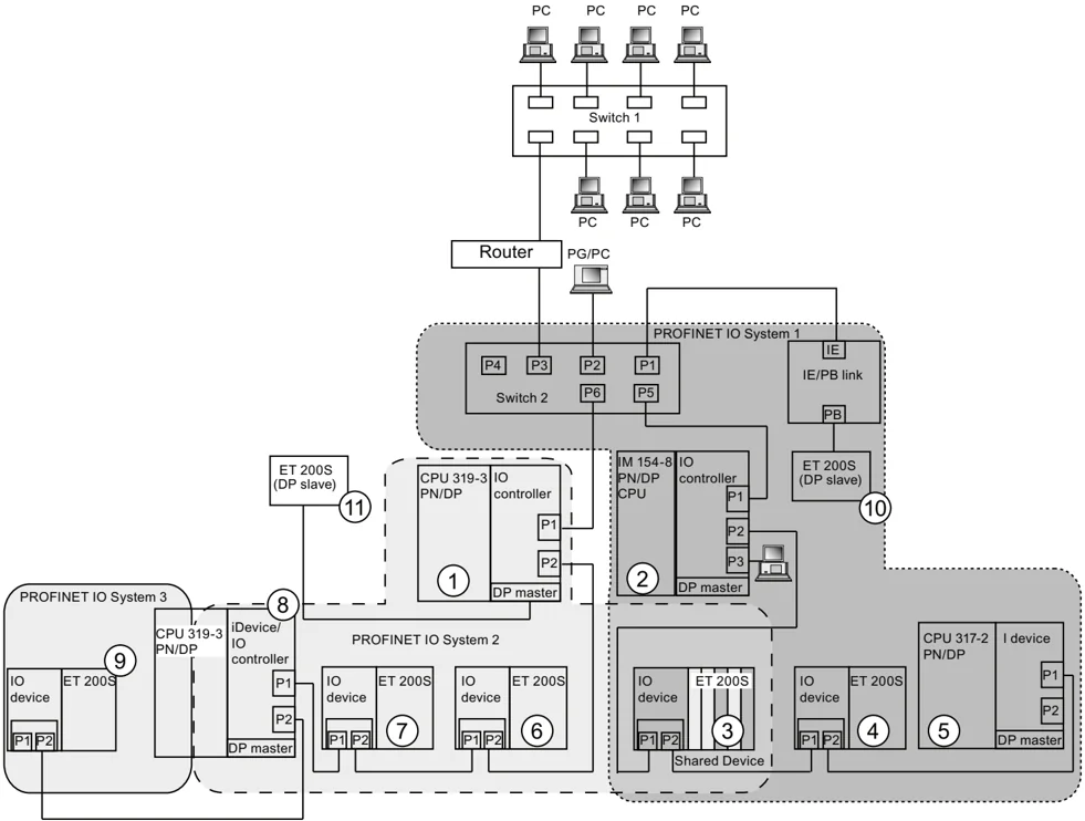
| The graphic shows | Examples of connection paths |
|---|---|
| The connection of company network and field level | You can access devices at the field level from PCs in your company networkExample:• PC - Switch 1 - Router - Switch 2 - CPU 319-3 PN/DP ①. |
| Connections between the automation system and field level | You can also access other areas on the Industrial Ethernet from a programming device at the field level.Example:• PG - integrated switch IM 154-8 CPU ② - Switch 2 - integrated switch CPU 319--3 PN/DP ① - integrated switch IO Device ET 200 S ⑤ - on IO Device ET 200S ⑥. |
90
Configuring
4.11 Planning subnets
| The graphic shows | Examples of connection paths |
|---|---|
| The IO controller of the CPU IM 154-8 CPU ② sets up PROFINET IO system 1 and directly controls devices on the Industrial Ethernet and PROFIBUS. | At this point, you can see the IO feature between the IO controller, intelligent device, and the IO devices on the Industrial Ethernet:• IM 154-8 CPU ② acts as IO controller for the IO devices ET 200S ③ and ET 200S ④, for switch 2, and for the intelligent device CPU 317-2 PN/DP ⑤.• IO device ET 200S ③ is operated as shared device, which means that IM154-8 CPU ② operating as controller can access only the (sub)modules it has been assigned as controller for that IO device.• The IM 154-8 CPU ② is also the IO controller for ET 200S (DP slave) ⑩ by way of IE/PB Link. |
| The CPU 319-3 PN/DP ① operates as IO controller for PROFINET system 2 and, at the same time, as DP master on the PROFIBUS. In addition to other IO devices, this IO controller is used to operate a CPU319-3 PN/DP ⑧ as intelligent device which, in turn, operates a PROFINET subsystem as IO controller. | Here you can see that a CPU can be both the IO controller for an IO device and the DP master for a DP slave:• CPU 319-3 PN/DP ① is the IO controller for the IO devices ET 200S ⑥ and ET 200S ⑦, and for the intelligent device CPU 319-3 PN/DP ⑧.• Moreover, CPU319-3 PN/DP ① shares the IO device ET 200S ③ with IO controller IM 154-8 CPU ②, which means that the CPU319-3 PN/DP ① operating as controller can access only the (sub)modules it has been assigned as controller for that IO device.• CPU319-3 ⑧, which is operated as intelligent device on CPU319-3 PN/DP ①, also acts as IO controller and sets up its own PROFINET system 3 on which the IO device ET 200S ⑨ is operated.• The CPU 319-3 PN/DP ① is the DP master for one DP slave ⑪. The DP slave ⑪ is assigned locally CPU 319-3 PN/DP ① and is not visible on the Industrial Ethernet. |
Additional information
You will find additional information about PROFINET in the documents listed below:
- In the System Description PROFINET (http://support.automation.siemens.com/WW/view/en/19292127)
- In the From PROFIBUS DP to PROFINET IO programming manual. This manual also provides a clear overview of the new PROFINET blocks and system status lists.
91
Configuring 4.11 Planning subnets
4.11.4 Routed network transitions
Example: Programming device access beyond network limits (routing) A CPU with several interfaces can also serve as a router for intercommunication with different subnets. With a PG you can access all modules on local and remote networks.
Requirements:
- Implement STEP 7 starting with Version 5.0. Note: For STEP 7 requirements with respect to the CPUs used, refer to the technical specifications.
- Assign the PG/PC to a network in your STEP 7 project (SIMATIC Manager, assigning a PG/PC).
- The various networks are interconnected using modules with routing functions.
- After you configured all networks in NETPRO, initiated a new compilation for all stations, and then download the configuration to all modules with routing function. This also applies to all changes made in the network.
All routers therefore know all paths to a destination station.
92
Configuring
4.11 Planning subnets
Access to remote networks
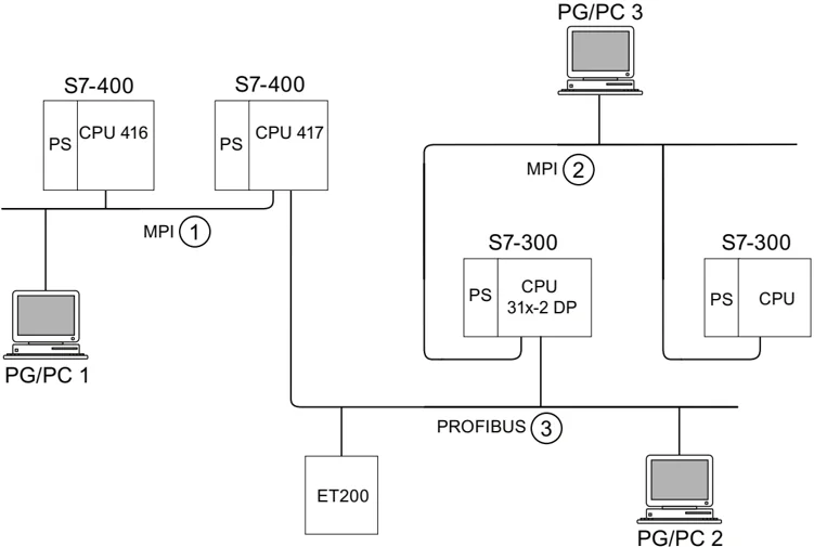
Figure 4-8 Access to remote networks
Example 1 To access the CPU 31x-2 DP using PG/PC 1: PG/PC 1 - MPI network ① - CPU 417 as router - PROFIBUS network ③ - CPU 31x-2 DP
Example 2 To access the the S7-300 CPU (on the right in the figure) using PG/PC 2: PG/PC 2 - PROFIBUS network ③ - CPU 31x-2 DP as router - MPI network ② - S7-300 CPU
Example 3 To access the 416 CPU using PG/PC 3: PG/PC 3 - MPI network ② - CPU 31x-2 DP as router - PROFIBUS network ③ - CPU 417 as router - MPI network ① - CPU 416
Note Only for CPUs with DP interface: If these CPUs are operated as I-slaves and you want to use routing functionality, set the Commissioning / Debug Mode / Routing check box in the DP Interface for DP Slave dialog box in STEP 7.
Reference You can find more information on the subject of routing in the "Communication with SIMATIC" manual.
93
Configuring 4.11 Planning subnets
4.11.5 Point-to-point (PtP)
Availability CPUs with the "PtP" name suffix have at least one PtP interface.
Properties Using the PtP interface of your CPU, you can connect external devices with serial interface. You can operate such a system at transmission rates up to 19.2 kbps in full duplex mode (RS 422), and up to 38.4 kbps in half duplex mode (RS 485).
Baud rate
- Half duplex: 38,4 kbps
- Full duplex: 19,2 kbps
Drivers PtP communication drivers installed in those CPUs:
- ASCII drivers
- 3964(R) Protocol
- RK 512 (CPU 314C-2 PtP only)
Devices capable of PtP communication Devices equipped with a serial port, for example, barcode readers, printers, etc.
Reference CPU 31xC: Technological functions manual
4.11.6 Actuator/sensor interface (ASI)
Actuator/Sensor Interface (ASI) Implementation using communication processors (CP).
The ASI, or Actuator/Sensor Interface, represents a subnet system on the lowest process level for automation systems. It is designed especially for networking digital sensors and actuators. The maximum data volume is 4 bit per slave station.
S7-300 CPUs require communication processor for the ASI connection.
94
Installing
5.1 Installing an S7-300
Here we will explain the steps required for the mechanical assembly of an S7-300.
Note
Note the installation guidelines and notes on safety in this manual when mounting, commissioning and operating S7-300 systems.
Open components
S7-300 modules are "Open Components" according to IEC 61131-2 and an "open type" according to UL/CSA Approval.
In order to conform with specifications on safe operation relating to mechanical strength, inflammability, stability and touch-protection, the following alternative installation modes are prescribed:
• Installation in a suitable cubicle
• Installation in a suitable cabinet
• Installation in an appropriately equipped and closed operating area
Access to these areas must only be possible with a key or tool. Only trained or authorized personnel are allowed access to these cubicles, cabinets or electrical operating rooms.
95
Installing 5.1 Installing an S7-300
Accessories included
Installation accessories are included with the module package. The appendix contains a list of accessories and spare parts together with the corresponding order numbers.
Table 5- 1 Module accessories
\begin{tabular}{|l|l|l|} \hline Module & Accessories included & Explanation \ \hline CPU & 1 x Slot number label & For assigning slot numbers \ \cline{2-3} & Inscription labels & for the MPI address and Firmware Version (all CPUs) for labeling of integrated inputs and outputs (CPU 31xC only) \ \hline Signal module (SM) & 1 Bus connector & For electrical interconnection of modules \ \cline{2-3} Function Module (FM) & 1 Labeling strip & For labeling module I/O \ \hline Communication module (CP) & 1 Bus connector & For electrical interconnection of modules \ \cline{2-3} & 1 Inscription label (only CP 342-2) & For labeling the AS interface connector \ \hline Interface module (IM) & 1 Bus connector & For electrical interconnection of modules \ \cline{2-3} & 1 x Slot number label (only IM 361 and IM 365) & For assigning slot numbers on racks 1 to 3 \ \hline \end{tabular}
Tip: Templates for the labeling strips are available on the Internet (http://support.automation.siemens.com/WW/view/en/11978022).
Tools and materials required
To install the S7-300, you require the tools and materials listed in the table below.
Table 5- 2 Installation tools and materials
\begin{tabular}{|l|l|} \hline You require ... & for ... \ \hline cutting the 2 m rail to length & commonly available tool \ \hline scribing and drilling holes on the 2 meter rail & commonly available tool, 6.5 mm diameter drill bit \ \hline screw-mounting the rail & wrench or screwdriver, matching the selected fixing screws diverse M6 screws (length depends on the place of installation) with nuts and spring lock washers \ \hline screw-fastening the modules on the rail & screwdriver with 3.5 mm blade width (cylindrical design) \ \hline pulling out the grounding slide contact to achieve ungrounded state & screwdriver with 3.5 mm blade width (cylindrical design) \ \hline \end{tabular}
96
5.2 Installing the mounting rail
Mounting rail versions available
- Ready-to-use, four standard lengths (with 4 holes for fixing screws and 1 ground conductor bolt)
- One meter mounting rail
May be shortened to any special length. Supplied without holes for fixing screws and without ground conductor bolt.
Requirement
Prepare the 2 m mounting rail for installation.
Preparing the 2 m mounting rail for installation
- Cut the 2 m mounting rail to the required length.
- Mark out:
- four bores for the fixing screws
(for dimensions, refer to "Dimensions for fixing holes") - one hole for the protective conductor bolt.
- four bores for the fixing screws
- If the length of your rail exceeds 830 mm, you must stabilize it by providing additional holes for fixing it with more screws.
Mark out these holes along the groove in the middle section of the rail (see the Figure below). The pitch should be approx. 500 mm. - Drill the marked holes with a diameter of 6.5 +□.□mm for M6 screws.
- Mount an M6 bolt for fixing the ground conductor.
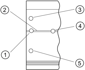
| Number | Description |
|---|---|
| ① | Hole for the ground conductor bolt |
| ② | Groove for drilling additional holes for mounting screws |
| ③ | Hole for the mounting screw |
| ④ | Additional hole for mounting screw |
| ⑤ | Hole for the mounting screw |
Operating Instructions, □□/□□□□, A5E00105492-12
97
Installing 5.2 Installing the mounting rail
Dimension of the mounting holes
The mounting hole dimensions for the mounting rail are shown in the table below.
Table 5- 3 Mounting holes for rails
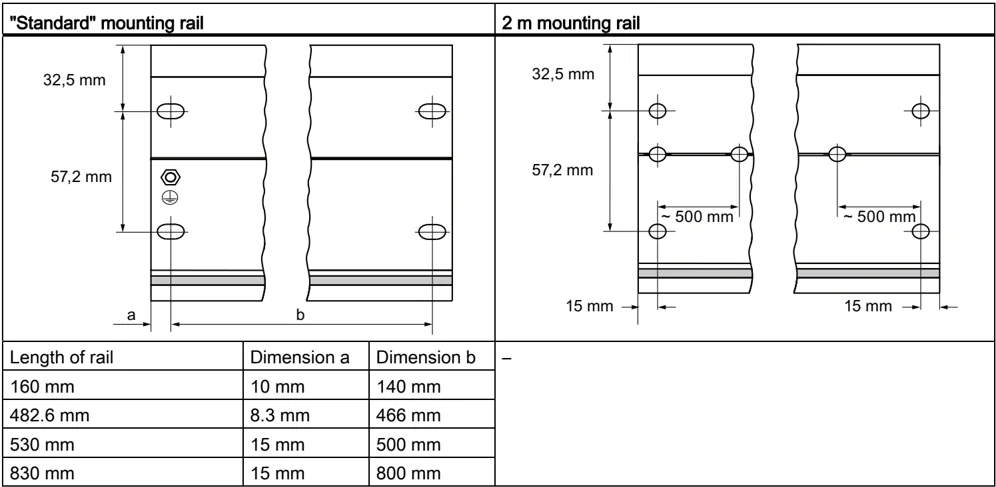
a b Length of rail | Dimension a | Dimension b 160 mm | 10 mm | 140 mm 482.6 mm | 8.3 mm | 466 mm 530 mm | 15 mm | 500 mm 830 mm | 15 mm | 800 mm
32,5 mm 57,2 mm ~ 500 mm 15 mm 32,5 mm 57,2 mm ~ 500 mm 15 mm –
Fixing screws
You can use the following screw types for mounting the rails:
| For ... | you can use ... | Explanation |
|---|---|---|
| outer fixing screws | Cylindrical head screw M6 to ISO 1207/ISO 1580 (DIN 84/DIN 85) | Choose a suitable screw length for your assembly. You also need size 6.4 washers to ISO 7092 (DIN 433) |
| M6 hexagonal head screw to ISO 4017 (DIN 4017) | ||
| Additional fixing screws (only 2 meter mounting rail) | Cylindrical head screw M6 to ISO 1207/ISO 1580 (DIN 84/DIN 85) |
98
Installing
5.2 Installing the mounting rail
Installing the mounting rail
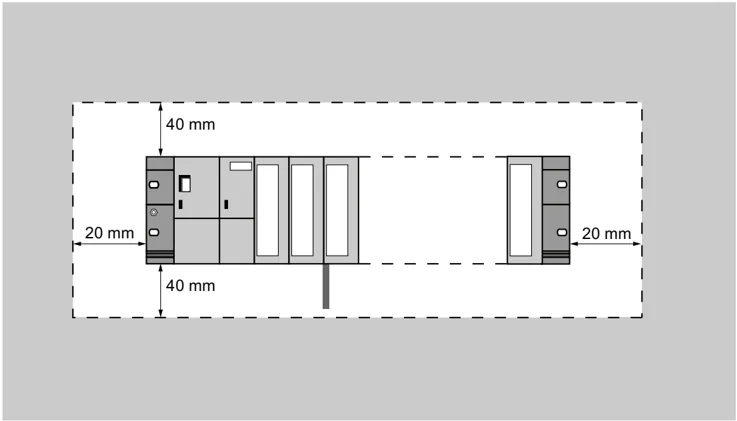
- Install the mounting rails so that sufficient space is available for installing modules and to allow heat dissipation (clearance of at least 40 mm above and below the modules. See the figure below).
- Mark up the mounting holes on the mounting surface. Drill the holes with a diameter of $6.5^{+0.2}$ mm.
- Screw the rail (M6 screws) onto the mounting surface.
Note
Always make sure of a low-impedance contact between the rail and a mounting surface, if the latter is a grounded metal panel or equipment mounting panel. On varnished or anodized metals, for instance, use a suitable contacting agent or contact washers.
The figure below shows the clearance required for the installation of an S7-300.
99
5.3 Installing modules on the mounting rail
Rules governing
The table below shows you points to follow when wiring, installing or removing S7-300 modules.
| Rules for the tightening torque of.. | ... power supply, CPU,SM, FM, CP |
|---|---|
| Fixing modules to the mounting rail | from 0.8 Nm to 1.1 Nm |
Requirements for module installation
- The configuration of the automation system is completed.
- The mounting rail is installed.
Mounting order of the modules
Hang the modules onto the rail, starting at the left and in the following order:
- Power supply module
- CPU
- SMs, FMs, CPs, IMs
Note
Please check before you insert any SM 331 analog input modules whether you have to reposition the measuring range submodules at the side of the module. For more information, see the "Analog modules" chapter in the Module Data Manual.
Note
When installing an S7-300 system with ungrounded reference potential, make the relevant settings on the CPU. You ideally do so before you mount any modules onto the rail.
Installation steps
The various steps in module installation are explained below.
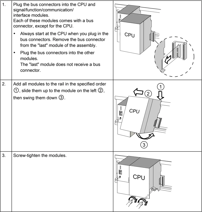
| 1. | Plug the bus connectors into the CPU and signal/function/communication/ interface modules. Each of these modules comes with a bus connector, except for the CPU. • Always start at the CPU when you plug in the bus connectors. Remove the bus connector from the "last" module of the assembly. • Plug the bus connectors into the other modules. The "last" module does not receive a bus connector. | |
|---|---|---|
| 2. | Add all modules to the rail in the specified order ①, slide them up to the module on the left ②, then swing them down ③. | |
| 3. | Screw-tighten the modules. |
See also
Installing an S7-300 with ungrounded reference potential (not CPU 31xC) (Page 45)
101
Installing 5.4 Labeling modules
5.4 Labeling modules
Assign slot numbers
You should assign a slot number to each one of the mounted modules, thus making it easier to assign the modules in the configuration table in STEP 7. The table below shows the slot number assignment.
Table 5- 4 Slot numbers for S7 modules
\begin{tabular}{|l|l|l|} \hline Slot numbes & Module & Remark \ \hline 1 & Power supply (PS) module & – \ \hline 2 & CPU & – \ \hline 3 & Interface module (IM) & to the right of the CPU \ \hline 4 & 1. Signal module (SM) & to the right of the CPU or IM \ \hline 5 & 2. Signal module & – \ \hline 6 & 3. Signal module & – \ \hline 7 & 4. Signal module & – \ \hline 8 & 5. Signal module & – \ \hline 9 & 6. Signal module & – \ \hline 10 & 7. Signal module & – \ \hline 11 & 8. Signal module & – \ \hline \end{tabular}
102
Installing
5.4 Labeling modules
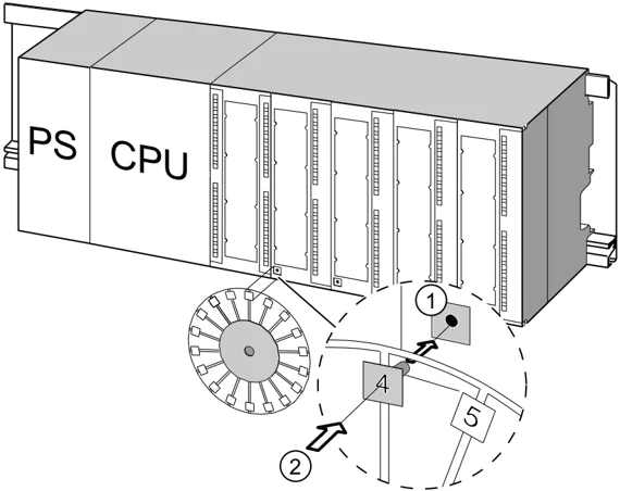
Attach the slot numbers to the modules.
- Hold the corresponding slot number in front of the relevant module.
- Place the tongue in the opening on the module ①.
- Press the slot number into the module ②. The slot number breaks off from the wheel.
The figure below illustrates this procedure. The slot number labels are included with the CPU.
103
Installing 5.4 Labeling modules
104
Wiring
6.1 Requirements for wiring the S7-300
This chapter describes the requirements for wiring the power supply, CPU and front connectors.
Accessories required
The following accessories are required for wiring the S7-300.
Table 6- 1 Wiring accessories \begin{tabular}{|l|l|} \hline Accessories & Explanation \ \hline Front connectors & for connecting the sensors / actuators of the system to the S7-300 \ \hline Labeling strips & for labeling the module I/Os \ \hline Shield connection element, shielding terminals (matching the shielding diameter) & for connecting cable shielding \ \hline \end{tabular}
Tools and material required
Tools and materials required for wiring the S7-300.
Table 6- 2 Tools and material for wiring \begin{tabular}{|l|l|} \hline To ... & you need ... \ \hline Connect the protective conductor to the rail & Wrench (size 10) \par Protective conductor cable (cross-section ≥ 10 mm$^2$) with M6 cable lug \par M6 nut, washer, spring lock washer \ \hline Adjust the power supply module to mains voltage & Screwdriver with a blade width of 4.5 mm \ \hline Wire the power supply module and the CPU & Screwdriver with a 3.5-mm blade, side-cutters, stripping tool \par Flexible cable, for example, sheathed flexible cable 3 x 1.5 mm$^2$ \par Wire end ferrules to DIN 46228 \ \hline Wire the front connector & Screwdriver with a 3.5-mm blade, side-cutters, stripping tool \par Flexible cables, 0.25 mm$^2$ to 0.75/1.5 mm$^2$ \par Shielded cables as required \par Wire end ferrules to DIN 46228 \ \hline \end{tabular}
105
Wiring 6.1 Requirements for wiring the S7-300
Wiring conditions for power supply and CPU
Table 6- 3 Wiring conditions for power supply and CPU \begin{tabular}{|l|l|} \hline \textbf{Connectable cables} & \textbf{to power supply and CPU} \ \hline Solid conductors & No \ \hline Flexible conductors & \ \quad \bullet without wire end ferrule & 0.25 mm^2 to 2.5 mm^2 \ \quad \bullet With wire end ferrule & 0.25 mm^2 to 1.5 mm^2 \ \hline Number of conductors per terminal & 1 or 2, up to 1.5 mm^2 (total) in a common wire end ferrule \ \hline Diameter of the conductor insulation & max. 3.8 mm \ \hline Stripped length & 11 mm \ \hline Wire end ferrules to DIN 46228 & \ \quad \bullet without insulating collar & Design A, 10 mm to 12 mm length \ \quad \bullet with insulating collar & Design E, up to 12 mm length \ \hline Tightening torque & from 0.5 Nm to 0.8 Nm \ \hline \end{tabular}
Wiring conditions for front connectors
Table 6- 4 Wiring conditions for front connectors \begin{tabular}{|l|l|l|} \hline \textbf{Connectable cables} & \multicolumn{2}{l|}{\textbf{Front connectors}} \ \cline{2-3} & \textbf{20-pole} & \textbf{40-pole} \ \hline Solid conductors & No & No \ \hline Flexible conductors & & \ \quad \bullet without wire end ferrule & 0.25 mm^2 to 1.5 mm^2 & 0.25 mm^2 to 0.75 mm^2 \ \quad \bullet with wire end ferrule & 0.25 mm^2 to 1.5 mm^2 & 0.25 mm^2 to 0.75 mm^2 \ & & \bullet Mains feed 1.5 mm^2 \ \hline Number of conductors per terminal & 1 or 2, up to 1.5 mm^2 (total) in a common wire end ferrule & 1 or 2, up to 0.75 mm^2 (total) in a common wire end ferrule \ \hline Diameter of the conductor insulation & max. 3.1 mm & \bullet max. 2.0 mm for 40-pole cables \ & & \bullet max. 3.1 mm for 20-pole cables \ \hline Stripped length & 6 mm & 6 mm \ \hline Wire end ferrules to DIN 46228 & & \ \quad \bullet without insulating collar & Design A, 5 mm to 7 mm length & Design A, 5 mm to 7 mm length \ \quad \bullet with insulating collar & Design E, up to 6 mm length & Design E, up to 6 mm length \ \hline Tightening torque & \multicolumn{2}{l|}{from 0.4 Nm to 0.8 Nm} \ \hline \end{tabular}
106
Wiring 6.2 Bonding the Protective Conductor to the Mounting Rail
6.2 Bonding the Protective Conductor to the Mounting Rail
Requirement The mounting rail is fixed onto the mounting surface.
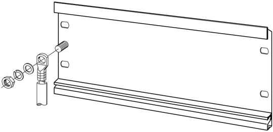
Connecting the protective conductor Connect the mounting rail to the protective conductor. The mounting rail is provided with a M6 protective conductor screw for this purpose. Minimum cross-section of the protective conductor: 10 mm² The figure below shows how the protective conductor has to be bonded to the rail.
Note Always make sure of a low-impedance contact between the protective conductor and the rail. You can achieve this by using a low-impedance cable, keeping it as short as possible and contacting it to a large surface. For example, an S7-300 mounted on a hinged frame must be connected to ground using a flexible grounding strap.
107
Wiring 6.3 Adjusting the power supply module to local mains voltage
6.3 Adjusting the power supply module to local mains voltage
Introduction You can operate the S7-300 power supply module on 120 VAC or 230 VAC. On older power supply modules PS307 with selectable input voltage range, the mains voltage is always set at the factory to the default 230 V.
Note On the new S7-300 power supplies PS307, the input voltage range is selected automatically. The MLFBs of the new power supply modules:
- PS307 2 A, 6ES7307-1BA01-0AA0
- PS307 5 A, 6ES7307-1EA01-0AA0
- PS307 10 A, 6ES7307-1KA02-0AA0
Setting the mains voltage selector switch Verify that the setting of the voltage selector switch matches your local mains voltage. To set the selector switch:
- Remove the protective cap with a screwdriver.
- Set the selector switch to match the local line voltage.
- Reinsert the protective cap.
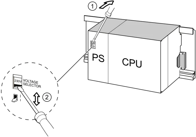
Numeral Designation ① Remove the protective cap with a screwdriver ② Set selector switch to mains voltage
108
Wiring 6.4 Wiring the power supply module and the CPU
6.4 Wiring the power supply module and the CPU
Requirement All modules are mounted onto the rail.
Wiring the PS and CPU
Note The PS 307 power supply module is equipped with two additional 24 VDC terminals L+ and M for the supply of I/O modules.
Note The power supply connector of your CPU is a plug-in device and can be removed.
WARNING There is a risk of contact to live wires if the power supply module, or any additional load power supply units, are connected to the mains. You should therefore isolate the S7-300 from power before you start wiring it. Always use crimp ferrules with insulating collars for the conductors. Close all front panels of the modules when you have completed the wiring. This is conditional before you reconnect the S7-300 to power.
- Open the PS 307 power supply module and CPU front panels.
- Open the strain relief on the PS 307.
- Strip the power cable to a length of 11 mm and connect it to L1, N and to the protective earth (PE) terminal of the PS 307.
- Screw-tighten the strain relief again.
- Next, wire the PS and CPU The power supply connector of the CPUs is a removable plug-in device. Strip the connecting cables for the CPU power supply to a length of 11 mm. Wire the lower terminal M on the PS 307 to the terminal M of the CPU and the lower terminal L+ on the PS 307 to terminal L+ of the CPU.
WARNING Reversing the polarity of the M and L+ terminals trips the internal fuse on your CPU. Always interconnect the M and L+ terminals of the power supply module and of the CPU.
- Close the front panels.
109


Wiring
6.4 Wiring the power supply module and the CPU
The figure below illustrates the procedures described earlier.
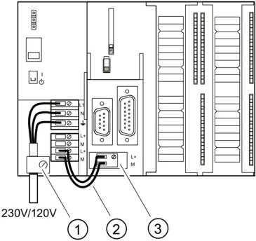
| Numeral | Designation |
|---|---|
| ① | Strain relief of the power supply cable |
| ② | Connection cables between the PS and CPU |
| ③ | Removable power supply connector |
Note
The PS 307 power supply module is equipped with two additional 24 VDC terminals L+ and M for the supply of I/O modules.
Wiring 6.5 Wiring front connectors
6.5 Wiring front connectors
Introduction
The sensors and actuators of your system are connected to the S7-300 AS by means of front connectors. Wire the sensors and actuators to the front connector and then plug it into the module
Front connector versions
Front connectors come in 20-pin and 40-pin versions with screw contacts or spring terminals. You require 40-pin front connectors for the CPUs 31xC and 32-channel SMs.
Use the following front connectors as required for the module:
Table 6- 5 Assignment of front connectors to modules
Connecting on spring terminals
It is quite easy to wire a front connector with spring terminals: Simply insert the screwdriver vertically into the opening with the red opening mechanism, insert the wire into the terminal and remove the screwdriver.
WARNING
You might damage the spring clamp mechanism of the front connector if you turn the screwdriver sideways or use the wrong size of screwdriver. Always slide a matching screwdriver vertically into the desired opening until it reaches the mechanical stop. This ensures that the spring terminal is fully open.
Tip
There is a separate opening for test probes up to 2 mm in diameter to the left of the opening for the screwdriver.
111

Wiring 6.5 Wiring front connectors
Requirement
The modules (SM, FM, CP 342-2) are mounted on the rail.
Preparing the front connectors and cables
WARNING
There is a risk of contact to live wires if the power supply module, or any additional load power supply units, are connected to the mains.
You should therefore isolate the S7-300 from power before you start wiring it. Close all front panels of the modules when you have completed the wiring. This is conditional before you reconnect the S7-300 to power.
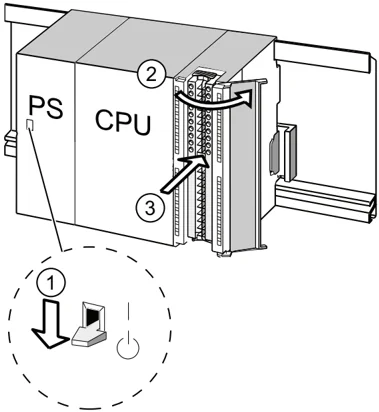
- Switch off the power supply.
- Open the front door.
- Place the front connector into wiring position.
Push the front connector into the signal module until it latches. In this position, the front connector still protrudes from the module.
Advantage of this wiring position: Convenient wiring. The front connector has no contact with the module in this wiring position.
- Strip the conductors to a length of 6 mm.
- Crimp the wire end ferrules, for example, to terminate two conductors at one terminal.

Numeral Designation ① Power supply (PS) turned off ② Open module ③ Front connector in wiring position
112
Wiring 6.5 Wiring front connectors
Wiring front connectors
Table 6- 6 Wiring front connectors
Reference
For information on wiring the integrated I/O of 31xC CPUs, refer to the CPU 31xC and CPU 31x, Technical Data manual.
Wiring 6.6 Plugging the front connectors into modules
6.6 Plugging the front connectors into modules
Requirement The front connectors are completely wired.
Inserting the front connector
Table 6-7 Inserting the front connector
</td>
114
Wiring 6.7 Wiring I/O modules and compact CPUs with Fast Connect
6.7 Wiring I/O modules and compact CPUs with Fast Connect
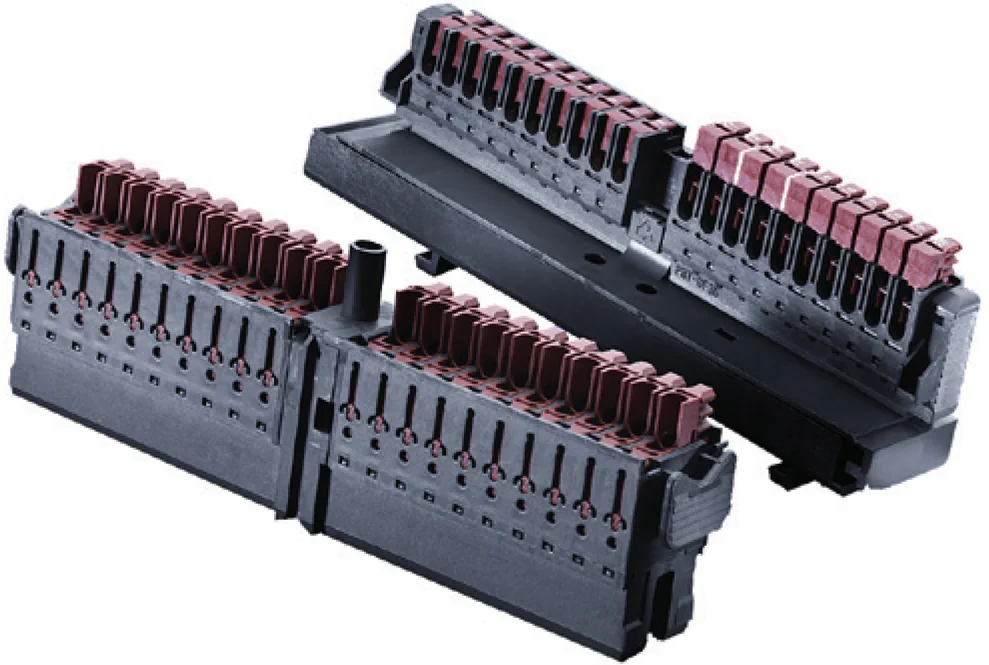
Order numbers for Fast Connect Connectors
- 20-pin connector: 6ES7392-1CJ00-0AA0
- 40-pin connector: 6ES7392-1CM00-0AA0
115
Wiring I/O modules and compact CPUs with Fast Connect
- I/O modules and compact CPUs can be wired with Fast Connect. The individual wires are connected by means of the front connector using Fast Connect technology, which requires no stripping.
- Fast Connect is a connection method that requires no conductor preparation (i.e., the conductor insulation does not have to be stripped).
- Each terminal with Fast Connect has a test opening (e.g. for measuring the voltage). The test opening is suitable for test probes with a maximum diameter of 1.5 mm.
- Wire end ferrules are not permitted.
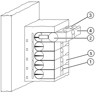
| Name | Designation |
|---|---|
| ① | Opening for testing: max. Ø 1.5 mm |
| ② | Opening for a conductor: 0.25 mm² to 1.5 mm² |
| ③ | Toothing for opening the terminal |
| ④ | Guide clip opened (the wire can be inserted) |
| ⑤ | Guide clip closed (the wire is connected) |
Figure 6-1 Schematic representation of Fast Connect connectors
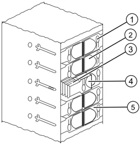
Wiring 6.7 Wiring I/O modules and compact CPUs with Fast Connect
Wiring rules for front connector with Fast Connect
Required tools Screwdriver, 3.0 mm or 3.5 mm.
Connectable cables • Flexible conductors with PVC insulation and a conductor cross-section of: 0.25 mm² to 1.5 mm² A list of the tested conductors can be found at: http://www.weidmueller.de
UL-compliant cables and connections Wiring range for insulating piercing connection 22 -16 AWG solid/stranded PVC insulated conductors, UL style no. 1015 only.
Wiring 6.7 Wiring I/O modules and compact CPUs with Fast Connect
Procedure for wiring with Fast Connect
- Insert the unstripped wire into the round opening until it stops (the insulation and conductor must form a flat surface) and secure the conductor in this position. – For 20-pin connector: at a 90° angle – For 40-pin connector: at a 45° angle
- Insert the screwdriver into the indentation on the topside of the guide clip.
- Press the screw driver downwards until the guide clip is engaged in the end position. The wire is connected.
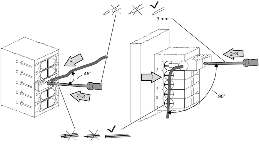
Note If you would like to reuse a conductor after it was already connected once then it must be trimmed beforehand.
118
Wiring 6.7 Wiring I/O modules and compact CPUs with Fast Connect
Procedure for disconnecting the wiring with Fast Connect
- Insert the screwdriver into the opening next to the guide clip until it stops.
- Using the screwdriver, apply upward leverage to the guide clip by means of the appropriate toothing. Repeat this action until the guide clip is engaged in the top position.
- The wiring is disconnected. Remove the wire.
 Figure 6-2 Disconnecting the wiring of a 40-pin Fast Connect connector
 Figure 6-3 Disconnecting the wiring of a 20-pin Fast Connect connector
119
Wiring 6.8 Labeling the module I/Os
6.8 Labeling the module I/Os
Introduction
The labeling strips are used to document the assignment of module I/Os to the sensors / actuators of your system.
You have to use the following labeling strips, depending on the module:
Table 6- 8 Assignment of labeling strips to modules \begin{tabular}{|l|l|} \hline Module & Labeling strip order no.: \ \hline SMs (not 32-channel), & 6ES7392-2XX00-0AA0 \ Function modules, & \ Communication module CP 342-2 & \ \hline SMs (32-channel) & 6ES7392-2XX10-0AA0 \ \hline \end{tabular}
Filling out and inserting labeling strips
- Label the strips with the addresses of the sensors / actuators.
- Slide the labeled strips into the front panel.
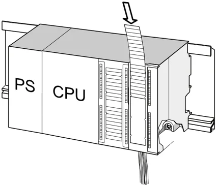
Tip
Templates for the labeling strips are available on the Internet under Internet (http://support.automation.siemens.com/WW/view/en/11978022).
120
Wiring 6.9 Terminating shielded cables on the shield connection element
6.9 Terminating shielded cables on the shield connection element
Application The shield connection element allows easy grounding of all shielded cables of S7 modules, due to its direct contact to the mounting rail.
Design of the shield connection element The shield connection element consists of
- a bracket with two screw bolts for rail mounting (order no.: 6ES7390-5AA00-0AA0) as well as
- the shielding terminals.
You must use the following shielding terminals, based on the shielding diameter of your cables:
Table 6-9 Shielding diameter assignment to shielding terminals \begin{tabular}{|l|l|} \hline Cable with shielding diameter & Shielding terminal order no.: \ \hline 2 cables, each with shielding diameter of 2 mm to 6 mm & 6ES7390-5AB00-0AA0 \ \hline 1 cable, shielding diameter 3 mm to 8 mm & 6ES7390-5BA00-0AA0 \ \hline 1 cable, shielding diameter 4 mm to 13 mm & 6ES7390-5CA00-0AA0 \ \hline \end{tabular}
The shield connection element is 80 mm wide and provides space for 4 shielding terminals each in two rows.
121
Wiring 6.9 Terminating shielded cables on the shield connection element
Installing the shield connection element underneath two signal modules
- Push the two screw bolts of the bracket into the guide on the underside of the mounting rail.
- Place the bracket underneath the modules whose shielded cables are to be terminated.
- Screw-tighten the bracket onto the rail.
- The shielding terminal is equipped with a slotted web underneath. Place the shielding terminal at this position onto the edge of the bracket (see figure below). Push the shielding terminal down and pivot it into the desired position.
You can install a maximum of 4 shielding terminals on each of the two rows of the shield connection element.
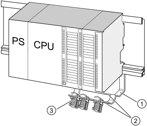
Numb Designation er ① Bracket of shield connection element ② Edge of the bracket where the shielding terminal(s) has/have to be placed ③ Shielding terminals
122
6.9 Terminating shielded cables on the shield connection element
Terminating 2-wire cables on shield connection elements
Only one or two shielded cables may be terminated per shielding terminal (see the figure below). The cable is clamped down at the stripped cable shielding.
- Strip the cable shielding to a length of at least 20 mm.
- Clamp in the stripped cable shielding underneath the shielding terminal.
Push the shielding terminal towards the module ① and feed the cable through the clamp opening ②.
If you need more than four shielding terminals, start wiring at the rear row of the shield connection element.
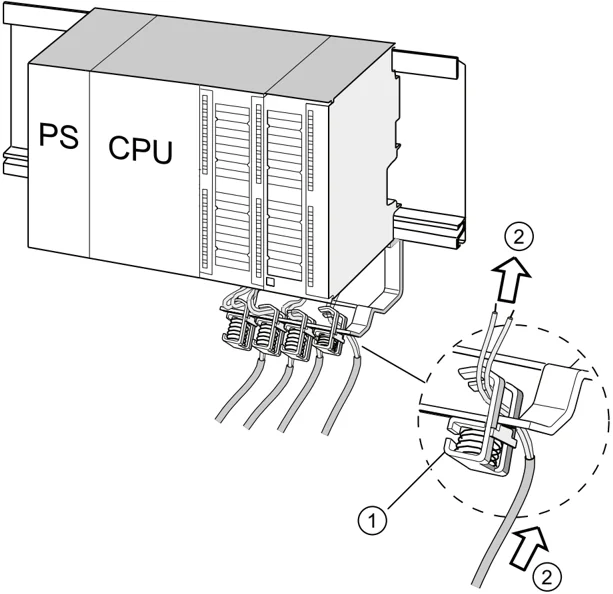
| Number | Designation |
|---|---|
| ① | Magnified view of the shielding terminal |
| ② | Wiring of the shielding terminal |
Tip
Provide a sufficient cable length between the shielding terminal and the front connector. This allows you to disconnect the front connector for repairs, without having to disconnect the shielding terminal also, for example.
See also
Cable shielding (Page 272)
123
Wiring 6.10 Wiring bus connectors
6.10 Wiring bus connectors
You need to network all the nodes you integrate into a subnet of your system. The section below provides information about the wiring of the bus connectors.
6.10.1 MPI/PROFIBUS bus connector
Wiring a bus connector with screw terminals
- Strip the bus cable. For information about stripped lengths, refer to the product information included with the bus connector.
- Open the bus connector housing.
- Insert the green and the red wire into the screw-terminal block. Always ensure that you connect the same wires to the same terminal (for example., green wire to terminal A, red wire to terminal B).
- Press the cable sheath into the clamp. Make sure that the cable shield directly contacts the shielding contact surfaces.
- Screw-tighten the wire terminals.
- Close the bus connector housing.
Wiring a Fast Connect bus connector
- Strip the bus cable. For information about stripped lengths, refer to the product information included with the bus connector.
- Open the strain relief of the bus connector.
- Insert the green and red wire into the open contacting covers. Always ensure that you connect the same wires to the same terminal (for example., green wire to terminal A, red wire to terminal B).
- Close the contacting cover. This presses the conductors into the insulation displacement terminals.
- Screw-tighten the strain relief clamp. Make sure that the cable shield directly contacts the shielding contact surfaces.
Note Use a bus connector with 90° cable outlet.
124
Wiring 6.10 Wiring bus connectors
See also Network components of MPI/DP and cable lengths (Page 63)
6.10.2 Setting up the terminating resistor on the PROFIBUS connector
Inserting a bus connector in a module
- Connect the wired bus connector to the module.
- Screw the bus connector tightly onto the module.
- If the bus connector is installed on the beginning or end of a segment, enable the terminating resistor (switch position "ON"; see the picture below).
Note The bus connector 6ES7972-0BA30-0XA0 does not come with a terminating resistor. You cannot insert this type of bus connector at the beginning or end of a segment.
Please make sure during startup and normal operation that power is always supplied to nodes where the terminating resistor is active.
The figure below shows the switch settings of a bus connector:
Terminating resistor activated Terminating resistor not activated

Removing the fiber-optic cable You can unplug a bus connector with a looped-through bus cable at any time from the PROFIBUS DP interface without interrupting data exchange on the bus.
125
Wiring 6.10 Wiring bus connectors
Possible data traffic errors
WARNING Data traffic error might occur on the bus! A bus segment must always be terminated at both ends with the terminating resistor. For example, this is not the case when the last slave with the bus connector is deactivated. Because the bus connector takes its voltage from the station, this terminating resistor is ineffective. Please make sure that power is always supplied to stations on which the terminating resistor is active.
6.10.3 PROFINET bus connector
Wiring a Fast Connect bus connector
Devices are usually connected to the PROFINET interface by means of RJ45 connector. For an overview of the product range and applications of the RJ45 connector, refer to chapter "PROFINET cable length and network dimensions (Page 85)" When wiring the RJ45 connector by yourself, refer to the comprehensive installation instructions included. These instructions are also available on the Internet (http://support.automation.siemens.com/WW/view/en/20691879).
Special features for unlocking
In confined installation conditions, use a screwdriver with a 2.5 mm blade to unlock the connector.
126