Commissioning
8.4 Commissioning the Modules
STOP LED does not flash during the memory reset
What should I do if the STOP LED does not flash during the memory reset or if other LEDs are lit?
- You must repeat steps ② and ③.
- If the CPU still does not reset memory, evaluate the diagnostic buffer of the CPU.
What happens during a CPU memory reset?
Table 8-5 Internal CPU events on memory reset
| Event | Action in CPU | |
|---|---|---|
| CPU activities | 1 | The CPU deletes the entire user program in the main memory. |
| 2 | The CPU erases the retentive user data (bit memories, times, counters and DB contents) | |
| 3 | The CPU tests its own hardware. | |
| 4 | The CPU copies the runtime-relevant content of the SIMATIC Micro Memory Card (load memory) to work memory.Tip: If the CPU is unable to copy the contents from the SIMATIC MMC and requests a memory reset:• Remove the SIMATIC Micro Memory Card.• Reset CPU memory.• Read the diagnostic buffer.If the IP address and device name were not retentive (depending on the assignment mode):Assign a temporary IP address to the CPU and then read out the diagnostic buffer,ordetermine the MAC address of the CPU in SIMATIC Manager under "Available nodes". If the Ethernet interface of the programming device is set to "TCP/IP (Auto)", you can also use this available MAC address to read the diagnostic buffer, because STEP 7 will then assign a temporary IP address. | |
| Memory contents after reset | The user program is once again transferred from the SIMATIC MMC to work memory. Memory utilization is indicated accordingly. | |
| Data retained | • Data in the diagnostic buffer. After POWER OFF/POWER ON, only the last 100 entries in the diagnostic buffer are retentive.You can use the programming device to read the diagnostic buffer (see the STEP 7 Online Help). | |
| • The MPI interface parameters (MPI address and highest MPI address, transmission rate, configured MPI addresses of CPs/FMs in an S7300). | ||
| • The same applies to CPU 314C-2 PN/DP, CPU 315-2 PN/DP, CPU 317, CPU 319 if the MPI/DP interface of the CPU is programmed for operation as DP interface (PROFIBUS address, highest PROFIBUS address, baud rate, configured as active or passive interface). | ||
| • Parameters of the PROFINET interface:IP address parameters/device name (depending on the assignment mode, see chapter: Assigning IP address parameters and the device name (Page 137)). | ||
| The time. | ||
| Contents of run-time meter. |
152
Commissioning
8.4 Commissioning the Modules
Note
Communication shutdown during memory reset on PROFINET CPUs with integrated switch
Note that the PROFINET interface and the integrated switch are shut down when you reset memory on this CPU.
During the memory reset on a CPU configured within a line structure, communication via the CPU integrated switch to downstream devices is shut down.
After memory reset, the PROFINET interface is not restarted unless the interface parameters were saved to retentive memory.
The integrated switch is always restarted and can resume communication on completion of the CPU memory reset.
Special feature: Interface parameters
The following parameters hold a special position when CPU memory is reset.
- Parameters of an MPI or MPI/DP interface
- Parameters of a PROFINET interface
The table below describes which interface parameters are valid after a CPU memory reset.
| CPU memory reset ... | PROFINET interface parameters ... | MPI/DP parameters ... |
|---|---|---|
| with inserted SIMATIC Micro Memory Card | ... which are on the SIMATIC Micro Memory Card or integrated read-only load memory are valid. | |
| If no parameters are stored (SDB), the previously set parameters remain valid, provided they were saved to retentive memory (depending on the assignment mode, see chapter: Assigning IP address parameters and the device name (Page 137)) | If no parameters are stored (SDB), the previously set parameters remain valid (not valid for an interface with DP function only). | |
| without inserted SIMATIC Micro Memory Card | ... the previously set parameters remain valid, provided they were saved to retentive memory (depending on the assignment mode, see chapter: Assigning IP address parameters and the device name (Page 137)) | ... are retained and remain valid (not valid for an interface with DP function only). |
153
Commissioning 8.4 Commissioning the Modules
8.4.4 Formatting the Micro Memory Card
Situations which require formatting of the SIMATIC Micro Memory Card:
- The SIMATIC Micro Memory Card module type is not a user module
- The SIMATIC Micro Memory Card is not formatted
- The SIMATIC Micro Memory Card is defective
- Invalid content of the SIMATIC Micro Memory Card The content of the SIMATIC Micro Memory Card has been marked invalid
- The "Download user program" operation was interrupted as a result of Power Off.
- The "Write to EPROM" operation was interrupted as a result of Power Off.
- Error when evaluating the module content during CPU memory reset.
- Formatting error, or formatting failed.
If one of these errors has occurred, the CPU prompts you for yet another memory reset, even after a memory reset operation has been performed. The contents of the SIMATIC MMC are retained until it is formatted, unless the "Download user program" or "Write to EPROM" operation was interrupted due to Power Off.
The SIMATIC Micro Memory Card is only formatted if a specific reason is given (see above). It is not formatted, for example, when the CPU requests a memory reset after module replacement. In this case, a switch to MRES triggers a normal memory reset for which the module content remains valid.
How to format your SIMATIC Micro Memory Card
If the CPU has requested a memory reset (STOP LED flashing slowly) you can format the SIMATIC MMC using the mode selector switch as described below:
- Toggle the switch to the MRES position and hold it there until the STOP LED lights up and remains on (after approx. 9 seconds).
- Within the next three seconds, release the switch and toggle it once again to MRES position. The STOP LED flashes to indicate that formatting is in progress.
Note Always perform these steps within the specified time, for the SIMATIC Micro Memory Card will otherwise not be formatted and returns to memory reset status.
See also
CPU memory reset by means of mode selector switch (Page 150)
154
Commissioning 8.4 Commissioning the Modules
8.4.5 Connecting the programming device (PG)
8.4.5.1 Connect PG/PC to the integrated PROFINET interface of the CPU 31x PN/DP
Requirement
- CPU with integrated PROFINET interface (e.g., CPU 317-2 PN/DP)
- PG/PC with network card
Connect PG/PC to the integrated PROFINET interface of the CPU 31x PN/DP
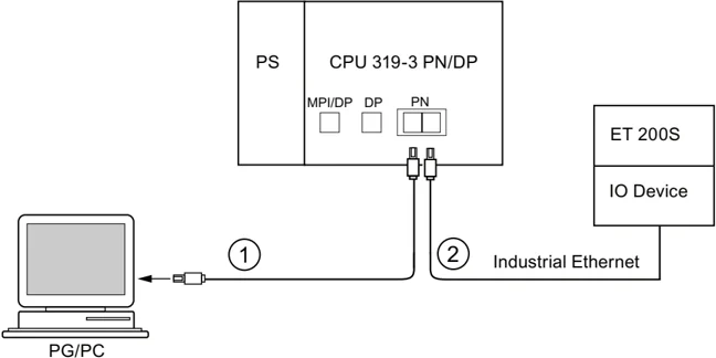
Number Meaning ① Using a preassembled twisted-pair cable, connect the programming device/PC to Port 1 of the PROFINET interface of the CPU. ② Using a twisted-pair cable, connect the IO device to Port 2 of the PROFINET interface of the CPU.
Reference
- For information on PROFINET, refer to the PROFINET System Description.
- For information on passive network components, refer to the manual SIMATIC NET: Twisted Pair and Fiber-Optic Networks.
See also
Configuring the PROFINET IO system (Page 182)
155
Commissioning 8.4 Commissioning the Modules
8.4.5.2 Connecting the PG to a node
Requirement The PG must be equipped with an integrated MPI interface or an MPI card in order to connect it via MPI.
Connecting a PG to the integrated MPI interface of the CPU Interconnect the PG with the MPI interface of your CPU by way of a PG patch cable ①. You can use a self-made PROFIBUS bus cable with bus connectors. The figure below illustrates the connection between the PG and the CPU.
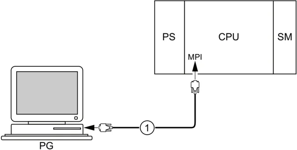
Number Description ① PG cable used to interconnect the PG with the CPU
Procedure for PROFIBUS DP The procedure is basically the same for PROFIBUS DP, if the CPU interface is set to PROFIBUS DP mode.
156
Commissioning 8.4 Commissioning the Modules
8.4.5.3 Connecting the PG to several nodes
Requirement
The PG must be equipped with an integrated MPI interface or an MPI card in order to connect it to an MPI.
Connecting the PG to several nodes
Use bus connectors to connect a PG which is permanently installed on the MPI subnet to the other nodes of the MPI subnet.
The figure below shows two networked S7-300s which are interconnected by means of bus connectors.
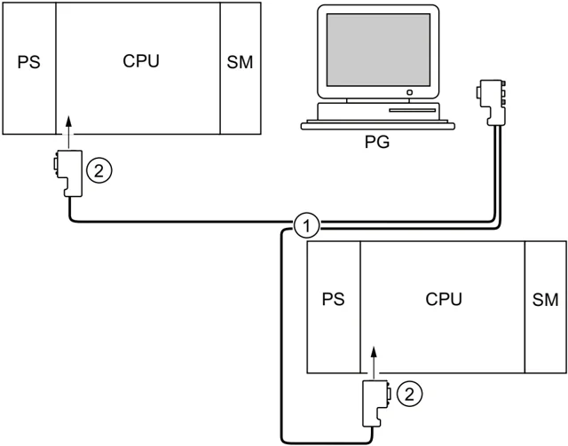
Numb Description er ① PROFIBUS bus cable ② Connectors with enabled terminating resistors
157
Commissioning 8.4 Commissioning the Modules
8.4.5.4 Using the PG for commissioning or maintenance
Requirement
The PG must be equipped with an integrated MPI interface or an MPI card in order to connect it to an MPI.
Using the PG for commissioning or maintenance
Use a stub cable to connect the commissioning and maintenance PG to the other subnet nodes. The bus connector of these nodes must be equipped with a PG socket.
The figure below shows the interconnection of two networked S7-300 and a PG.
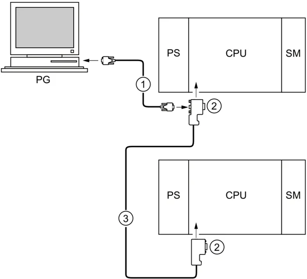
Number Description ① Stub cable for connection between programming device and CPU ② Connectors with enabled terminating resistors ③ PROFIBUS bus cable for linking both CPUs
158
Commissioning 8.4 Commissioning the Modules
MPI addresses for service PGs
If there is no stationary PG, we recommend:
To connect a PG to an MPI subnet with "unknown" node addresses, set the following addresses on the service PG:
- MPI address: 0
- Highest MPI address: 126
IN STEP 7, you then determine the highest MPI address on the MPI subnet and match the highest MPI address in the PG to that of the MPI subnet.
See also
Procedure: Commissioning the hardware (Page 141) Procedure: Software commissioning (Page 143)
159
Commissioning 8.4 Commissioning the Modules
8.4.5.5 Connecting a PG to ungrounded MPI nodes (not CPU 31xC)
Requirement The PG must be equipped with an integrated MPI interface or an MPI card in order to connect it to an MPI.
Connecting a PG to ungrounded nodes on an MPI subnet (not CPU 31xC)
Connecting a PG to ungrounded nodes Always use an ungrounded PG to connect to ungrounded MPI subnet nodes or to ungrounded S7-300 PLCs.
Connecting a grounded PG to the MPI You want to operate with ungrounded nodes. If the MPI at the PG is grounded, you must interconnect the nodes and the PG with an RS485 repeater. You must connect the ungrounded nodes to bus segment 2 if the PG is connected to bus segment 1 (terminals A1 B1) or to the PG/OP interface (refer to chapter 9 in the Module Data Manual).
The figure below shows an RS485 repeater as interface between grounded and ungrounded nodes of an MPI subnet.
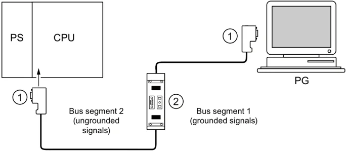
Number Description ① Connectors with enabled terminating resistors ② RS485 Repeaters, with activated terminating resistors
See also PROFINET cable lengths and network expansion (Page 85) Network components of MPI/DP and cable lengths (Page 63)
160
Commissioning 8.4 Commissioning the Modules
8.4.6 Starting SIMATIC Manager
Introduction SIMATIC Manager is a GUI for online/offline editing of S7 objects (projects, user programs, blocks, hardware stations and tools).
The SIMATIC Manager lets you
- manage projects and libraries,
- call STEP 7 tools,
- access the PLC (AS) online,
- edit Memory Cards.
Starting SIMATIC Manager After installation, the SIMATIC Manager icon appears on the Windows desktop, and the Start menu contains entry SIMATIC Manager under SIMATIC.
- Run SIMATIC Manager by double-clicking the icon, or from the Start menu (same as with all other Windows applications).
User interface A corresponding editing tool is started up when you open the relevant objects. You start the program editor by double-clicking the program block you want to edit (object-oriented start).
Online Help The online help for the active window is always called by pressing F1.
8.4.7 Monitoring and modifying inputs and outputs
The "Monitoring and modifying variable" tool Using the STEP 7 "Monitoring and modifying variable" tool, you can
- monitor program variables in any format
- edit the variable status or contents in the CPU (modifying).
161
Commissioning 8.4 Commissioning the Modules
Creating a variable table
You have two options for creating a variable table (VAT):
- in the LAD/FBD/STL editor by selecting the PLC > Monitor/Modify Variables command This table is also available directly online.
- in SIMATIC Manager with the Blocks container open via menu item Insert New Object > Variable table This table created offline can be saved for future retrieval. You can also test it after switching to online mode.
VAT structure:
In the VAT, every address to be monitored or modified (e.g. inputs, outputs) occupies one row.
The meaning of the VAT columns is as follows:
Monitor variable
You have two options for monitoring variables:
- updating the status values once via menu item Variable > Update Status Values or
- continuous update of status values via menu item Variable > Monitor
162
Commissioning 8.4 Commissioning the Modules
Modifying variable
To modify variables, proceed as follows:
- Left-click the field Modify value of the relevant variable.
- Enter the modify value according to the data type.
- To update modify values once, select the menu item Variable > Activate Modify Values. or Enable modify values permanently via menu item Variable > Modify.
- Use the Monitor test function to verify whether the modify value was entered in the variable.
Is the modify value valid?
You can disable the modify value entered in the table. An invalid value is displayed same as a comment. You can re-enable the modify value.
Only valid modify values can be enabled.
Setting the trigger points
Trigger points:
- The "Trigger point for monitoring" determines the time of update for values of variables to be monitored.
- The "Trigger point for modifying" determines the time for assigning the control values to the variables to be modified.
Trigger condition:
- The "Trigger condition for monitoring" determines whether to update values once when the trigger point is reached or continuously every time the trigger point is reached.
- The "Trigger condition for modifying" determines whether to assign control values once or permanently to the variables to be modified.
Start the settings of the trigger points in the "Monitoring and modifying variable" tool, Variable > Set triggers ... menu command.
Special features:
- If "Trigger condition for monitoring" is set to once, the menu items Variable > Update Status Values or Variable > Monitor have the same effect, namely a single update.
- If "Trigger condition for modifying" is set to once, the menu items Variable > Update modify values or Variable > Modify have the same effect, namely a single assignment.
- If trigger conditions are set to permanent, the said menu items have different effects as described above.
- If monitoring and modifying is set to the same trigger point, monitoring is executed first.
- If Process operation is set under Debug > Mode, value assignment does not take place in every cycle when permanent modifying is set. Remedy: Use the Force test function.
163
Commissioning
8.4 Commissioning the Modules
Saving/opening the variable table
Saving the VAT
- After aborting or completing a test phase, you can save the variable table to memory. The name of a variable table starts with the letters VAT, followed by a number from 0 to 65535; e.g. VAT5.
Opening VAT
- Select the menu item Table > Open.
- Select the project name in the Open dialog.
- In the project window below, select the relevant program and mark the Blocks container.
- In the block window, select the desired table.
- Confirm with OK.
establishing a connection to the CPU
The variables of a VAT represent dynamic quantities of a user program. In order to monitor or modify variables it is required to establish a connection to the relevant CPU. Every variable table can be linked to another CPU.
In menu item PLC > Connect to ... , establish a connection to one of the following CPUs:
- configured CPU
- directly connected CPU
- available CPU ...
The table below lists the display of variables.
| CPUs | The CPU variables are displayed, ... |
|---|---|
| configured CPU | in their S7 program (Hardware Station) in which the VAT is stored. |
| directly connected CPU | that is connected directly to the PG. |
| available CPU | that is selected in the dialog window.Use the menu items PLC > Connect to ... > Available CPU ... to connect to an available CPU. This can be used to connect to any CPU available on the network. |
164
Commissioning 8.4 Commissioning the Modules
Modifying outputs in CPU STOP mode
The function Enable PO resets the output disable signal for the peripheral outputs (PO), thus enabling modifying of the PO in CPU STOP mode.
In order to enable the POs, proceed as follows:
-
In menu item Table > Open the variable table (VAT), open the VAT that contains the PO you want to modify, or activate the window containing the corresponding VAT.
-
To modify the PO of the active VAT, select the CPU connection in menu command PLC > Connect to ....
-
Use menu command PLC > Operating Mode to open the Operating Mode dialog and switch the CPU to STOP mode.
-
Enter your values in the "Modify value" column for the PO you want to modify.
Examples: I/O output: POB 7 modify value: 2#0100 0011 POW 2 W#16#0027 POD 4 DW#16#0001
-
Select Variable > Enable PO to set "Enable PO" mode.
-
Modify the PO by selecting Variable > Activate Modify Values. "Enable PO" mode remains active until reset by selecting Variable > Enable PO to disable this mode.
"Enable PO" is also terminated when the connection to the programming device is canceled.
-
Return to step 4 if you want to set new values.
Note
For example, a message pops up to indicate a CPU mode transition from STOP to RUN or START-UP. A message also pops up if you select the "Enable PO" function while the CPU is in RUN mode.
165
Commissioning PROFIBUS DP
8.5.1 Commissioning the PROFIBUS DP network
Requirements
Requirements for commissioning a PROFIBUS DP network:
- A PROFIBUS DP network is installed.
- You have configured the PROFIBUS DP network using STEP 7 Standard Package and have assigned a PROFIBUS DP address and the address space to all the participants.
- Note that you must also set address switches at some of the DP slaves (see the description of the relevant DP slave).
- Software requirements are shown in the table below, based on the CPU used:
Table 8-6 Software requirements
| CPU | Order number | Software required |
|---|---|---|
| 313C-2 DP | 6ES7313-6CG04-0AB0 | STEP 7 as of V5.5 + SP1 or |
| 314C-2 DP | 6ES7314-6CH04-0AB0 | STEP 7 as of V5.3 + SP2 with HSP |
| 314C-2 PN/DP | 6ES7314-6EH04-0AB0 | STEP 7 as of V5.5 + SP1 or |
| STEP 7 as of V5.5 + HSP | ||
| 315-2 DP | 6ES7315-2AH14-0AB0 | STEP 7 as of V5.5 + SP1 or |
| STEP 7 as of V5.2 + SP1 + HSP | ||
| 315-2 PN/DP | 6ES7315-2EH14-0AB0 | STEP 7 as of V5.5 + SP1 or |
| STEP 7 as of V5.5 + HSP | ||
| 317-2 DP | 6ES7317-2AK14-0AB0 | STEP 7 as of V5.5 + SP1 or |
| STEP 7 as of V5.2 + SP1 with HSP | ||
| 317-2 PN/DP | 6ES7317-2EK14-0AB0 | STEP 7 as of V5.5 + SP1 or |
| STEP 7 as of V5.5 + HSP | ||
| 319-3 PN/DP | 6ES7318-3EL01-0AB0 | STEP 7 as of V5.5 |
DP address ranges of the CPUs
Table 8-7 DP address ranges of the CPUs
| Address range | 313C-2 DP314C-2 DP315-2 DP315-2 PN/DP | 314C-2 PN/DP | 317-2 DP317-2 PN/DP319-3 PN/DP |
|---|---|---|---|
| Entire address range of inputs and of outputs | 2048 Byte | 2048 Byte | 8192 Byte |
| of these in the process image, for inputs and outputs respectively | Max. 2048 bytes | Max. 2048 bytes | Max. 8192 bytes |
| • Default | 128 Byte | 256 Byte | 256 Byte |
DP diagnostic addresses
DP diagnostic addresses occupy 1 byte per DP master and DP slave in the input address range. For example, at these addresses DP standard diagnostics can be called for the relevant node (LADDR parameter of SFC 13). The DP diagnostic addresses are specified in your configuration. If you do not specify any DP diagnostic addresses, STEP 7 assigns these DP diagnostic addresses in ascending order, starting at the highest byte address.
In the case of a CPU 31xC-2 DP, CPU 31x-2 DP or CPU 31x PN/DP assigned as a master, two different diagnostic addresses must be assigned for S7 slaves.
-
Diagnostic address of the slave (address for slot 0)
At this address all slave events are reported in the DP master (Node representative), e.g. Node failure.
-
Diagnostic address of the module (address for slot 2)
All module (CPU 313C-2 DP as I-Slave, for example) events are reported in the master (OB82) at this address. With a CPU as DP Slave, for example, diagnostic interrupts for operating mode transitions are reported at this address.
See also
Connecting the PG to a node (Page 156)
Connecting the PG to several nodes (Page 157)
Commissioning 8.5 Commissioning PROFIBUS DP
8.5.2 Commissioning the CPU as DP master
Requirements for commissioning
- The PROFIBUS subnet has been configured.
- The DP slaves are ready for operation (see relevant DP slave manual).
- In order to operate the MPI/DP interface as DP interface, it must be configured accordingly (only CPU 314-2 PN/DP, CPU 315-2 PN/DP, CPU 317 and CPU 319).
- You must configure the CPU as DP master prior to commissioning. That is, in STEP 7 you have to – configure the CPU as a DP master, – assign a PROFIBUS address to the CPU, – assign a master diagnostic address to the CPU, – integrate the DP slaves into the DP master system.
Is the DP CPU a DP slave?
If so, this DP slave appears in the PROFIBUS DP catalog as configured station. In the DP master, assign a slave diagnostic address to this DP slave CPU. You must interconnect the DP master with the DP slave CPU and specify the address ranges for data exchange with the DP slave CPU.
Commissioning
Commission the DP CPU as a DP master in the PROFIBUS subnet as follows:
- Download the PROFIBUS subnet configuration created with STEP 7 (preset configuration) from the PG to the DP CPU.
- Switch on all of the DP slaves.
- Switch the DP CPU from STOP to RUN.
168
Commissioning 8.5 Commissioning PROFIBUS DP
Startup of DP CPU as DP master
During startup, the DP CPU checks the configured expected configuration of its DP master system against the actual configuration.
If preset configuration = actual configuration, the CPU switches to RUN mode.
If the preset configuration \neq to the actual configuration, the configuration of parameter Startup if preset configuration \neq actual configuration determines the startup behavior of the CPU.
\begin{tabular}{|p{0.48\textwidth}|p{0.48\textwidth}|} \hline \textbf{Startup when the preset configuration \neq actual configuration = yes (default setting)} & \textbf{Startup when the preset configuration \neq actual configuration = no} \ \hline DP CPU switches to RUN. \newline (BUSF LED flashes if any of the DP slaves cannot be addressed) & DP CPU remains in STOP mode, and the BUS LED flashes after the set \textbf{Monitoring time for transfer of parameters to modules}. \newline The flashing BUSF LED indicates that at least one DP slave cannot be accessed. In this case, check whether all DP slaves are switched on or correspond with your configuration, or read out the diagnostic buffer with STEP 7. \ \hline \end{tabular}
Recognizing the operating state of DP slaves (Event recognition)
The table below shows how the DP CPU operating as a DP master recognizes operating mode transitions of a CPU operating as a DP slave or data exchange interruptions.
Table 8- 8 Detecting operating mode transitions and station failure of DP CPUs operated as DP slave in the DP CPU as master
\begin{tabular}{|p{0.25\textwidth}|p{0.7\textwidth}|} \hline \textbf{Event} & \textbf{What happens in the DP master?} \ \hline Bus interruption \newline (short circuit, \newline connector removed) & \begin{itemize} \item Call of OB 86 with the message \textbf{Station failure} \newline (incoming event; diagnostic address of the DP slave assigned to the DP master) \item With I/O access: Call of OB 122 \newline (I/O access error) \end{itemize} \ \hline DP slave: \newline RUN \rightarrow STOP & \begin{itemize} \item Call of OB 82 with the message \textbf{Module error} \newline (incoming event; diagnostic address of the DP slave assigned to the DP master; variable OB82_MDL_STOP = 1) \end{itemize} \ \hline DP slave: \newline STOP \rightarrow RUN & \begin{itemize} \item Call of OB 82 with the message \textbf{Module OK} \newline (incoming event; diagnostic address of the DP slave assigned to the DP master; variable OB 82_MDL_STOP = 0) \end{itemize} \ \hline \end{tabular}
Tip: When commissioning the CPU as DP master, always program OB82 and OB86. This helps you to recognize and evaluate data exchange errors or interruption.
169
Commissioning 8.5 Commissioning PROFIBUS DP
Status/modify, programming via PROFIBUS
As an alternative to the MPI interface, you can program the CPU or execute the PG status and modify functions via the PROFIBUS DP interface.
Note
The use of Status and Modify via the PROFIBUS DP interface extends the DP cycle.
Constant bus cycle time
This is a property of PROFIBUS DP. The "Constant bus cycle time" function ensures that the DP master always starts the DP bus cycle within a constant interval. From the perspective of the slaves, this means that they receive their data from the master at constant time intervals.
In STEP 7 V5.x or higher, you can configure constant bus cycle times for PROFIBUS subnets. Details on constant bus cycle times are found in the STEP 7 Online Help.
Isochronous updating of process image partitions
SFC 126 "SYNC_PI" is used for the isochronous update of the process image partition of inputs. An application program which is interconnected with a DP cycle (by means of OB61) can use this SFC for consistent updates of data recorded in the process image partition of inputs in synchronism with this cycle. SFC126 accepts interrupt control and can only be called in OB61.
SFC 127 "SYNC_PO" is used for the isochronous update of the process image partition of outputs. An application program which is interconnected to a DP cycle can use the SFC for the consistent transfer of the computed output data of a process image partition of outputs to the I/O in synchronism with this cycle. SFC 127 accepts interrupt control and can only be called in OB 61.
The SFCs 126 and 127 are described in the STEP 7 Online Help and in the System Software S7-300/400, System and Standard Functions Reference Manual.
The following CPUs support isochronous mode at the PROFIBUS DP:
- CPU 315-2 DP
- CPU 315-2 PN/DP
- CPU 317-2 DP
- CPU 317-2 PN/DP
- CPU 319-3 PN/DP
CPUs with two DP interfaces (CPU 317-2 DP and CPU 319-3 PN/DP) only support isochronous mode on their second (DP) interface.
Note
Isochronous mode is possible on PROFIBUS or on PROFINET.
170
Commissioning
8.5 Commissioning PROFIBUS DP
Reference
For more information about the isochronous mode, refer to the Isochronous mode (http://support.automation.siemens.com/WW/view/en/15218045/) Manual.
Clock synchronization
For information about clock synchronization via PROFIBUS DP, refer to the CPU 31xC und CPU 31x Manual, Technical Specifications, chapter: Clock synchronization.
Sync/Freeze
The SYNC control command is used to set sync mode on the DP slaves of selected groups. In other words, the DP master transfers current output data and instructs the relevant DP slaves to freeze their outputs. The DP slaves writes the output data of the next output frames to an internal buffer; the state of the outputs remains unchanged.
Following each SYNC control command, the DP slaves of the selected groups transfer the output data stored in the internal buffer to the process outputs.
The outputs are only updated cyclically again after you transfer the UNSYNC control command using SFC11 "DPSYC_FR".
The FREEZE control command is used to set the relevant DP slaves to Freeze mode, in other words, the DP master instructs the DP slaves to freeze the current state of the inputs. It then transfers the frozen data to the input area of the CPU.
Following each FREEZE control command, the DP slaves freeze the state of their inputs again.
The DP master receives the current state of the inputs cyclically again only after you have sent the UNFREEZE control command with SFC11 "DPSYC_FR".
The SFC 11 is described in the corresponding STEP 7 Online Help and in the System Software S7-300/400, System and Standard Functions Reference Manual.
Startup of the DP master system
| DP CPUs as DP master |
|---|
| The Parameter transfer to modules parameter is also used to define the startup monitoring time for DP slaves. |
| That is, the DP slaves must startup and must have received all parameters from the CPU (as DP master) within the defined time. |
PROFIBUS address of the DP master
For the DP CPU, you must not set "126" as a PROFIBUS address.
171
Commissioning 8.5 Commissioning PROFIBUS DP
8.5.3 Commissioning the CPU as DP Slave
Requirements for commissioning
- The DP master is configured and programmed.
- If the MPI/DP interface of your CPU must be a DP interface, you must configure the interface as DP interface.
- Prior to commissioning, you must set the relevant parameters and configure the DP CPU for operation as DP slave. That is, in STEP 7 you have to
- "power on" the CPU as DP slave,
- assign a PROFIBUS address to the CPU,
- assign a slave diagnostic address to the CPU,
- specify whether the DP master is an S7 DP master or another DP master,
- specify the address ranges for data exchange with the DP master.
- All other DP slaves are programmed and configured.
GSD files
If you are working on an IM 308-C or third-party system, you require a GSD file to configure the DP CPU as a DP slave in a DP master system.
COM PROFIBUS V4.0 or later includes this GSD file.
When working with an older version or another configuration tool, you can download the GSD file from the Internet (http://support.automation.siemens.com/WW/view/en/10805317/133100).
Note This note applies to the CPUs 31xC-2 DP, CPU 315, CPU 317 and CPU 319.
If you wish to use the CPU as a standard slave using the GSD file, you must not set the Commissioning / Test mode check box on the DP interface properties dialog box when you configure this slave CPU in STEP 7.
Configuration and parameter assignment message frame
STEP 7 assists you during configuration and parameter assignment of the DP CPU. If you need a description of the configuration and parameter assignment frame, for example in order to use a bus monitor, you can find it on the Internet (http://support.automation.siemens.com/WW/view/en/1452338).
172