4 Machine operating area
4.6 Automatic mode
4.6.7 Program editing
Function
As soon as a syntax error in the part program is detected by the control, program execution is interrupted and the syntax error is displayed in the alarm line. You can switch to the program editor and monitor the program execution in a full-screen display. If an error occurs (Stop state), you can edit the program in the program editor.
Sequence of operations
"AUTO" mode is selected in the "Machine" operating area.
It is not possible to overtravel the point of interruption. The feedrate override switch is active. The program status is "Stopped" or "Reset".
E dit program
When you press this softkey, the correction editor is displayed, the softkey bars change and the softkey "Edit" is highlighted. If an error occurs, the faulty block is highlighted and can be corrected.
Using editor functions "Overwrite", "Highlight block", "Insert block", "Go To..." and "Find...", you can edit the program in the compensation block editor.
 or
You can toggle between program levels using these softkeys. Press "Level -" to view the program in which the faulty routine is called. You can return to the program to be edited by pressing "Level +". This is only possible if the NC has a compensation block.

After you have corrected the error, you can continue the program run by pressing "NC Start".
- NC Stop status: Only program lines that have not yet been executed can be edited.
- Reset status: All program lines can be edited.
Note: You cannot use the "Program editing" function if you are executing a program from the hard disk.

4
Machine operating area 4.6 Automatic mode
4

Additional information
If the error cannot be corrected in the "Channel aborted" state, an appropriate message is displayed when the "Compensation block" softkey is pressed.
In this case, program execution must be aborted with "NC Reset". The part program can then be edited under Programming.
4.6.8 Setting the block search/search target
Function
Block search offers the possibility of starting part program execution from almost any part program block. This involves the NC rapidly performing an internal run through the part program (without traversing motions) to the selected target block.
Here, every effort is made to achieve to the exact same control status as would result at the target block during normal part program execution (e.g., with respect to axis positions, spindle speeds, loaded tools, NC/PLC interface signals, variable values) in order to be able to resume automatic part program execution from the target block with minimum manual intervention.
4 Machine operating area 01/2008 4
4.6 Automatic mode
Block search
The following versions are available:
-
Without calculation on contour: No calculations are made during block search. The values stored in the control remain the same as they were before the block search.
-
With calculation on contour: During block search with calculation, the same calculations are performed as in normal program control. The complete target block is then executed in the same way as with normal program execution.
-
With calculation at block end point: During block search with calculation, the same calculations are performed as in normal program control. The interpolation mode valid in the target block is then applied to approach its end point or the next programmed position.
-
Multi-channel block search with calculation This block search is called SERUPRO in "Program test" mode. Single-channel applications are supported for parallel interaction with other functions. No axis movements are executed during the block search; however, all auxiliary functions are output to the PLC during the block search. The NC will start the selected program in Program test mode automatically. If the NC reaches the specified target block in the current channel, it stops at the beginning of the target block and deselects Program test mode again. The auxiliary functions up to the target block are not output. After continuing the program with NC start (after REPOS motion) the auxiliary functions of the target block are output.
The search target can be determined:
- Direct positioning
- By specifying a block number, a label, a program name or any character string
References
For further information about block search, please refer to: /FB1/ Function Manual Basic Functions; K1:
4
Machine operating area 4.6 Automatic mode 4
Sequence of operations
"AUTO" mode is selected in the "Machine" operating area. The channel is in reset status The program in which the block search is to be performed is selected.
Calls up the "block search" function. Position the cursor on the target block.
Notes
- If the target block is found, this block becomes the current block. HMI announces "Search target found" and displays the target block in the current block display.
- Action blocks (e.g., collection of auxiliary functions) are output after the first NC Start.
- Alarm 10208 is output to indicate that operator interventions such as Overstore or Mode Change after JOG are permissible.
- After the second NC Start, the program is started and the process resumes at this target block.
Block search start without calculation
Block search without calculation is used to find a part program block in the quickest possible way. No calculation of any type is performed. The control status at the target block remains unchanged compared to the status before the start of the block search.
Block search start with calculation on contour
Block search with calculation at contour is used to enable the programmed contour to be approached in any situation. On NC START, the start position of the target block or the end position of the block before the target block is approached. This is traversed up to the end position. Processing is true to contour.
Block search start with calculation at block end point
Block search with calculation at block end point is used to enable a target position (e.g., tool change position) to be approached in any situation. The end position of the target block or the next programmed position is approached using the type of interpolation valid in the target block. This is not true to contour. Only the axes programmed in the target block are moved.
4 Machine operating area 01/2008 4
4.6 Automatic mode
 Start of search run with calculation in "Program test" (SERUPRO) mode
SERUPRO (SEARCH RUN BY PROGRAMTEST) is block search run with calculation across all channels (channel modal). Here, the NC starts the selected part program in "Program test" mode. On reaching the target block, the program test is automatically deselected. This type of block search also enables interactions between the channel in which the block search is being performed and synchronized actions as well as with other NC channels.
Generally, the following applies to all block search run types: If necessary, a collision-free initial situation must be created manually on the machine in "JOG REPOS" mode before the start of further automatic part program execution.
Reset Block search can be aborted with Reset.
Define search target in program editor: The currently selected program level is displayed.
Position the cursor bar on a target block of your choice in the part program.
You can toggle between program levels using these softkeys if necessary.
Define search target in search pointer: Once the "search pointer" softkey has been pressed, a screen with the program pointer is displayed.
This contains input fields for program name, search type (block number, text, ...) and search target (content). The cursor is positioned in the input field for the "search type".
You must enter your selected search type for the search target in the "Type" input field.
Information about the available search types is displayed in the user response line.


The following search types can be entered:
| Search type (= jump to ...) | Value in search type field |
|---|---|
| End of program | 0 |
| Block number | 1 |
| Jump label | 2 |
| Any character string | 3 |
| Program name | 4 |
| Line number | 5 |
Different search types can be specified for different program levels.
You can enter your chosen search target (according to search type) in the "Search target" field.
You can enter the corresponding number of program passes in the "P" field (pass counter).
Preassign search target as last program interruption point: The search pointer is assigned the data of the last program interruption point.
4.6.9 Accelerated external block search
Function
The block search function allows you to run the part program forward until you reach the block you require. You can use the "External without calc." softkey in the "Search position" and "Search pointer" menus to start an accelerated block search in programs that are executed from an external device (local hard disk or network drive).
The search target can be determined:
- By directly positioning the cursor on the target block, or
- Specifying a block or line number
Block search sequence:
Only those programs and program parts which are needed in order to reach the specified search target and to continue program execution are transferred to the NC. This applies to the following:
- “Execution from external source”
- Execution of EXTCALL instructions

4.6 Automatic mode
Example:
The following search targets are entered in the Block search menu:
- Search target 1 “Level1”: MAIN1.MPF “Line”: 8
- Search target 2 “Level2”: SUBPRG2.SPF “Line”: 4000
- Search target 3 “Level3”: SUBPRG3.SPF “Line”: 2300
Programs
MAIN1.MPF
1 G90 2 X100 Y200 F2000 3 EXTCALL "SUBPRG1" 4 X200 Y400 5 EXTCALL "SUBPRG2" 6 EXTCALL "SUBPRG3" 7 X0 Y0 8 EXTCALL "SUBPRG2" 9 X50 10 M30
SUBPRG2.SPF
1 X200 Y300 2 X400 Y500 3 EXTCALL "SUBPRG3" . . 4000 EXTCALL "SUBPRG3" . . 5000 M17
SUBPRG3.SPF
1 X20 Y50 2 . . 2300 X100 Y450 . . 5000 M17
A distinction is made between the following two cases for block search:
- The main program MAIN1.MPF is in the NC, the subprograms SUBPRG1.SPF to SUBPRG3.SPF are executed from an external source.
- The main program MAIN1.MPF and the subprograms SUBPRG1.SPF to SUBPRG3.SPF are executed from an external source.
Case 1
- Search target 1: The NC does not consider the EXTCALL calls in lines 3, 5, and 6 of the main program MAIN1.MPF and jumps to the search target Line 8.
- Search target 2: The NC jumps to the search target at line 4000 of external subprogram SUBPRG2.SPF; the previous statements in the external program are skipped.
- Search target 3: The NC jumps to the search target at line 2300 of external subprogram SUBPRG3.SPF; the previous statements are skipped, and the search stops.
On NC Start, the subprogram SUBPRG3.SPF is processed starting at the target line.
Case 2
- Search target 1: The NC jumps to line 8 of the search target.
- Search target 2: See above
- Search target 3: See above
On NC Start, the subprogram SUBPRG3.SPF is started and executed starting at the target line.
Sequence of operations
"AUTO" mode is selected in the "Machine" operating area.
The channel is in reset status
The program in which the block search is to be performed is selected.
Switches to the "Search position" dialog.
Define search target in program editor:
The currently selected program level is displayed.
The block search via "Search position" is only possible for programs which have been loaded onto the NC and not for programs executed from the hard disk.
Position the cursor bar on a target block of your choice in the part program.

4 Machine operating area 01/2008 4.6 Automatic mode
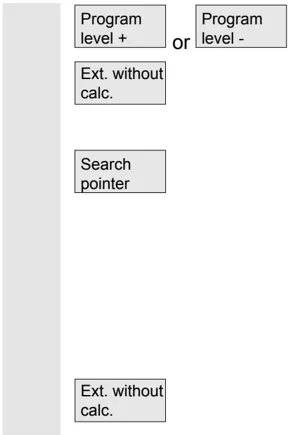
Program level + or Program level - If an interruption point is available on the NC, you can switch back and forth between the program levels.
Ext. without calc. Start search without calculation for external programs.
Define search target in search pointer: Once the "search pointer" softkey has been pressed, a screen form with the program pointer is displayed. This contains input fields for program name, search type (block number, text, ...) and search target (content). The cursor is positioned in the input field for the "search type". Type 1 (block number) and type 5 (line number) are possible as search target types.
Search pointer
Ext. without calc. Start search without calculation for external programs.
4.6.10 Block search in Program test mode, multi-channel

Function The NC is operated in Program test mode for this block search, so that interactions between channel and synchronous actions and between multiple channels are possible within an NCU. The "Block search in Program test mode" enables a program advance up to the desired point of the part program with the following functions: During "Block search in Program test mode", the NC outputs all auxiliary functions to the PLC and the part program commands for channel coordination (WAITE, WAITM, WAITMC, Axis replacement, Write variables, etc.) are carried out by the NC.
- This means that the PLC is updated during this block search and
- Machining operations involving multiple channels are executed correctly within the block search.
You can select the function via the "Prog. test Contour" softkey in the "Search position" and "Search pointer" menus.
You can define the search target by
- Directly positioning the cursor on the target block, or
- Using the input fields "Program name", "Search type" and "Search target".

4
Machine operating area
4.6 Automatic mode
Sequence of operations
Prerequisite:
- "AUTO" is selected as operating mode.
- All channels are in the Reset state.
- The program in which the block search is to be performed is selected.
The channel in which the target block is searched for or the program pointer set is the target channel. Other channels are started according to the setting in the "machine.ini" file.
Block search
Switches to the "Search position" dialog.
Define search target in program editor:
Search position
The currently selected program level is displayed.
Position the cursor bar on a target block of your choice in the part program.
Program level +
or
Program level -
You can toggle between program levels using these softkeys if necessary.
Prog.test contour
Start of search in Program test mode.
A dialog message appears as soon as all the channels involved in the current search have exited Program test mode. This message indicates that Repos offsets may, depending on the particular part program, have been produced in the channels involved during the block search and will be retracted by the NC through interpolation the next time it starts. You must acknowledge this message.
The repositioning offsets that occur may be traversed manually in JOG mode before continuing program processing with the "NC Start" key at the program position reached in the block search.
Define search target in search pointer:
Search pointer
Once the "search pointer" softkey has been pressed, a screen with the program pointer is displayed.
This contains input fields for program name, search type (block number, text, ...) and search target (content). The cursor is positioned in the input field for the "search type".
Prog.test contour
Start of search in Program test mode.

4 Machine operating area 01/2008 4
4.6 Automatic mode
A dialog message appears as soon as all the channels involved in the current search have exited Program test mode, see "Search target in program editor mode" above. Any repositioning offsets (in the individual channels) can be retracted in sequence via manually controlled traversing movements in JOG mode, before program processing is continued via NC Start at the point in the program reached by the block search.
4.6.11 Overstore
Function
In "AUTO" mode, you can overstore technological parameters (auxiliary functions, all programmable instructions ...) in the working memory of the NC. You can also enter and execute any NC block.
Sequence of operations
"AUTO" mode is selected in the "Machine" operating area.
Overstore with single block: The program automatically stops at the next block boundary.
 Single Block
Overstore
The "Overstore" window is opened.
In this window, you can now enter the NC blocks that are to be executed.
 Cycle Start
The blocks you have entered are executed and displayed in the "Current block" window. The "Overstore" window and associated softkeys are not displayed again until the control switches to the "Channel interrupted", "NC Stop" or "NC Reset" state.
More blocks can be added to the overstore buffer when these blocks have been executed.
Note: After "Overstore", a subprogram with the content REPOSA is executed. The program is displayed for the user.


4
Machine operating area 4.6 Automatic mode
Overstore without single block:
The main menu for "AUTO" mode is selected.
Stop the program by pressing "NC Stop".
The "Overstore" window is opened.
In this window, you can now enter the NC blocks that are to be executed.
The blocks you have entered are executed, the "Current block" window is opened and the softkeys disappear. The "Overstore" window and associated softkeys are not displayed again until the control switches to the "Channel interrupted", "NC Stop" or "NC Reset" state.
More blocks can be added (to the overstore buffer) when these blocks have been executed.
Additional information
- You can close the window and exit the Overstore function by pressing the "Recall" key. You have now exited the Overstore function.
- You cannot change operating modes until you have deselected "Overstore" with the "Recall" key.
- The program that was selected before Overstore is now resumed in "AUTO" mode when you press "NC Start" again.
- Overstore does not alter the programs stored in the part program memory.

4 Machine operating area 4.6 Automatic mode 01/2008 4
4.6.12 Program control
Function
You can use this function to change a program sequence in "AUTO" and "MDA" modes. The following program control functions can be activated or deactivated:
DRY Dry run feedrate ROV Rapid traverse override M01 Programmed stop 1 MFct* Programmed stop 2
DRF DRF selection PRT Program test
SBL1 Single block with STOP after each machine function SBL2 Single block with STOP after each block SBL3 Stop in cycle MFct* The M function defined in the machine data is displayed.
- "Skip blocks" softkey: You can activate up to 10 skip levels in respect of SKP skip blocks. See machine manufacturer's specifications.
- "Block display" softkey: Block display modes during program execution: Either all blocks are displayed or only motion blocks.
The display is dependent on the machine data of the operator panel front in which access authorization can be set.
References
For further information, please refer to Section 2.5, under "Program control display" /FB/, A2, Various interface signals, Chapter 4, or /FB/ K1, BAG, Channel, Program control
DRY
Program control with DRY
When you select the DRY function "dry run feedrate" in "Automatic" mode, the feedrate entered in setting data SD 42100: DRY_RUN_FEED is applied in the program instead of the programmed feedrate.
4 01/2008 Machine operating area 4.6 Automatic mode 4
SKP: Activate skip levels
It is possible to skip blocks, which are not to be executed every time the program runs (10 skip levels). Blocks to be skipped are indicated in the part program by an oblique "/" before the block number. The skip levels in the part program are specified by "/0" or by "/" to "/9". You can activate/deactivate skip levels in the following window:
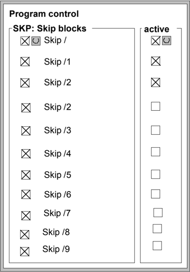
This program control window is displayed only if more than 1 skip level was set via machine data. Only the set skip levels are displayed. Changes to machine data are described in Section 9.1.
Display activated skip levels If more than one skip level is active, the right column indicates whether the PLC has transmitted the skip level selection to the NC. This allows you to see from the top window which level
- ☒ is selected, but ☐ not yet active
- ☒ selected and ☒ active
- ☐ deselected and ☒ active
- ☐ deselected and ☐ not active.

4 Machine operating area 01/2008 4
4.6 Automatic mode
Sequence of operations
"AUTO" or "MDA" mode is selected in the "Machine" operating area.
Program control Press the "Program control" horizontal softkey.
Another window pane, "Program control", appears on the main screen. The softkey bars change and the softkeys of the skip blocks and block display appear in the vertical menu.

Each actuation of the "toggle key" activates or deactivates the selected program control function.
Skip blocks
The block display appears in an extended "program control" window pane and can be selected with the "Block display" vertical softkey.
Skip blocks Press the "Skip blocks" vertical softkey.
The "Skip blocks" vertical softkey is only displayed if more than 1 skip level was set in MD 9423: MA_MAX_SKP_LEVEL. The levels to be skipped can only be changed when the control is in the Stop/Reset state.
Place the cursor at the required position.

Each press of the "Toggle key" activates or deactivates the selected skip level in the "Program control" window.
Additional information
The entries influence the program control display (see Section 2.5). The program control display is output irrespective of the selected menu.
References
For further information about how to program skip levels, please see: /PG/, Programming Guide Fundamentals

4
Machine operating area 4.6 Automatic mode
Block display during program execution
Block display during program execution appears in an extended "Program control" window pane and can be selected with the "Block display" vertical softkey.
Press the "Block display" vertical softkey.

Program execution modes
A separate "program control" window pane with the previous block display appears on the main screen. You can select the following while the program is running:
Block display during program execution
Display all blocks Display traversing blocks only
Current block
The last current block is shown in the block display. If you want to display all current blocks, you can use the selection menu to choose the desired block.
M Fct*
When this function is active, program execution on the NC is interrupted on request by the PLC at blocks in which the additional associated M function is programmed for a conditional stop 2.
The M Fct* number displayed here can be changed to the desired value in the Commissioning operating area under Machine Data/Channel MD by selecting the machine data corresponding to the M function. The number stored in this machine data is then displayed. The value of this auxiliary M function number must match the programmed stop 2.
Additional information
Blocks which are too long for the display window (approx. 65 characters) are truncated and the truncated code is replaced by "...".
4 Machine operating area 01/2008 4
4.6 Automatic mode
4.6.13 DRF offset
Function DRF is an axial technique that acts in the basis coordinate system. It is only permissible to select the handwheel via the axial interface – i.e. only machine axis names may be used.
Switch-on/switch-off The DRF offset can be switched on and off for specific channels by means of the "Program control" function. It remains stored until
- Power ON is performed for all axes
- DRFOF (selection of DRF via part program)
- PRESETON (modification of the actual value through Preset)
Alter DRF You can alter the DRF offset by traversing the appropriate machine axis using the handwheel (the actual value display does not change).
Sequence of operations "AUTO" mode is selected in the "Machine" operating area. The standard axis assignment is defined.
Enter the desired handwheel or select via the MCP.
Handwheel INC or [VAR] DRF Offset
Enter the desired increment or select via the MCP.
The "DRF offset" window is displayed.
Traverse the required axes using the handwheel.
Using the same operating sequence, you can also return the DRF offset to the value "0".
Parameters operating area
-
5.1 Tool data ........ 5-159
-
5.1.1 Tool offset structure ........ 5-159
-
5.1.2 Tool types and tool parameters ........ 5-159
-
5.2 Tool offset ........ 5-174
-
5.2.1 Function and main screen Tool offset ........ 5-174
-
5.2.2 New tool ........ 5-176
-
5.2.3 Display tool ........ 5-177
-
5.2.4 Deleting a tool ........ 5-178
-
5.2.5 New cutting edge ........ 5-179
-
5.2.6 Deleting a cutting edge ........ 5-180
-
5.2.7 Determining a tool offset ........ 5-180
-
5.2.8 Make tool offset immediately effective ........ 5-181
-
5.3 Tool management ........ 5-182
-
5.3.1 Main tool management functions ........ 5-183
-
5.3.2 Displaying/editing tool data ........ 5-190
-
5.3.3 Change in the significance/representation of tool wear values ........ 5-194
-
5.3.4 Grinding data expansion ........ 5-197
-
5.3.5 Load ........ 5-199
-
5.3.6 Unload ........ 5-203
-
5.3.7 Relocating ........ 5-205
-
5.3.8 Tool master data in the tool catalog ........ 5-206
-
5.3.9 Tool offset data in the tool cabinet ........ 5-209
-
5.3.10 Job processing of tools ........ 5-211
-
5.4 R parameters (calculation parameters) ........ 5-221
-
5.5 Setting data ........ 5-222
-
5.5.1 Working area limitation ........ 5-222
-
5.5.2 JOG data ........ 5-223
-
5.5.3 Spindle data ........ 5-224
-
5.5.4 Dry run feedrate for dry run operation DRY ........ 5-225
-
5.5.5 Starting angle for thread cutting ........ 5-226
-
5.5.6 Miscellaneous setting data ........ 5-227
-
5.5.7 Protection zones ........ 5-228
-
5.5.8 Electronic gear ........ 5-229
-
5.6 Zero/work offset ........ 5-230
-
5.6.1 Function ........ 5-230
-
5.6.2 Edit the settable work offset (G54 ...) ........ 5-232
-
5.6.3 Global zero offset/frame ........ 5-232
-
5.6.4 Displaying an active settable work offset ........ 5-235
-
5.6.5 Displaying an active programmable work offset ........ 5-236
-
5.6.6 Displaying an active external work offset ........ 5-237
-
5.6.7 Display the sum of the active work offsets ........ 5-237
-
5.6.8 Activate active work offset and basic frame immediately ........ 5-238
-
5.6.9 Actual value display: Settable zero system, SZS ........ 5-238
5 Parameters operating area
-
5.7 Define user data ........ 5-239
-
5.7.1 Define variables (GUD, PUD, LUD) ........ 5-239
-
5.7.2 Editing/finding user data ........ 5-240
-
5.7.3 Activate user data (GUD) ........ 5-242
-
5.8 Display system variables ........ 5-244
-
5.8.1 Creating variable views ........ 5-245
-
5.8.2 Managing variable views ........ 5-247
-
5.8.3 Logging system variables ........ 5-248
©Siemens AG 2008 All rights reserved.
5
Parameters operating area 5.1 Tool data 5
5.1 Tool data
5.1.1 Tool offset structure
A tool is selected in the program with the T function. Numbers T0 to T32000 can be assigned to tools. Each tool can have up to 9 cutting edges: D1-D9. D1 to D9 activates the tool offset of a cutting edge for the active tool. The tool length compensation is applied with the first traversing motion (linear or polynomial interpolation) of the axis. A tool radius compensation is activated by programming of G41/42 in the active plane (G17, 18, 19) and in a program block with G0 or G1.
Tool wear Allowances for changes in the active tool shape can be made in the tool length (tool parameters 12-14) and tool radius (tool parameters 15-20).
Tool offset with flat D numbers The so-called "flat D numbers" can be activated by means of NC machine data. This means that tool management is no longer available. The D number range increases to 1 - 32000. A D number can be assigned only once for each tool, i.e., each D number represents precisely one tool offset data record.
5.1.2 Tool types and tool parameters
Entries T No. Tool number D No. Cutting edge number Every data field (offset memory) that can be called with a D number contains not only the geometric information for the tool but also further entries, i.e., the tool type (drill, milling cutter, turning tools with cutting edge position, etc.).
©Siemens AG 2008 All rights reserved.

5 Parameters operating area 01/2008 5
5.1 Tool data
Tool types
Tool type classification:
- Group type 1xx (milling cutters):
- 100 Milling cutter to CLDATA
- 110 Ball-end cylindrical die-sinking cutter
- 111 Ball-end tapered die-sinking cutter
- 120 End mill (without corner rounding)
- 121 End mill (with corner rounding)
- 130 Angle head cutter (without corner rounding)
- 131 Angle head cutter (with corner rounding)
- 140 Facing tool
- 145 Thread cutter
- 150 Side mill
- 151 Saw
- 155 Bevel cutter
- 156 Bevel cutter with rounding
- 157 Tapered die-sinking cutter
- 160 Drill and thread milling cutter
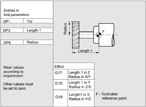
Required offset values for a milling cutter
\begin{tabular}{|l|l|l|} \hline Entries in & & \ tool parameters & & \ \hline DP1 & 1xy & \ \hline & & \ \hline DP3 & Length 1 & \ \hline & & \ \hline DP6 & Radius & \ \hline & & \ \hline Wear values & Effect & \ according to & G17: & Length 1 in Z \ requirement & & Radius in X/Y \ \cline{2-3} & G18: & Length 1 in Y \ & & Radius in Z/X \ \cline{2-3} Other values must & G19: & Length1 in X \ be set to zero & & Radius in Y/Z \ \hline \end{tabular}
F - Toolholder reference point
5-160 ©Siemens AG 2008 All rights reserved.
5 01/2008 Parameters operating area 5.1 Tool data 5
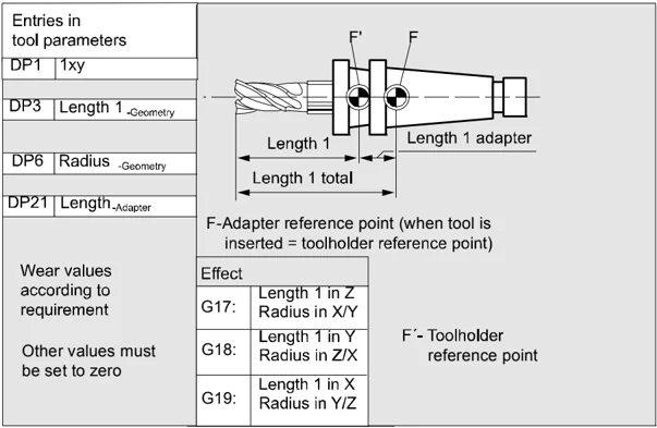
Milling cutter with adapter
\begin{tabular}{|l|l|l|} \hline Entries in tool parameters & & \ \hline DP1 & 1xy & \ \hline DP3 & Length 1^-Geometry & \ \hline DP6 & Radius^-Geometry & \ \hline DP21 & Length^-Adapter & \ \hline Wear values according to requirement & Effect & \ \hline & G17: & Length 1 in Z Radius in X/Y \ \hline Other values must be set to zero & G18: & Length 1 in Y Radius in Z/X \ \hline & G19: & Length 1 in X Radius in Y/Z \ \hline \end{tabular}
F-Adapter reference point (when tool is inserted = toolholder reference point) F' - Toolholder reference point
- Group type 2xx (drills):
- 200 Twist drill
- 205 Drill
- 210 Boring bar
- 220 Center drill
- 230 Countersink
- 231 Counterbore
- 240 Tap regular thread
- 241 Tap fine thread
- 242 Tap Whitworth thread
- 250 Reamer
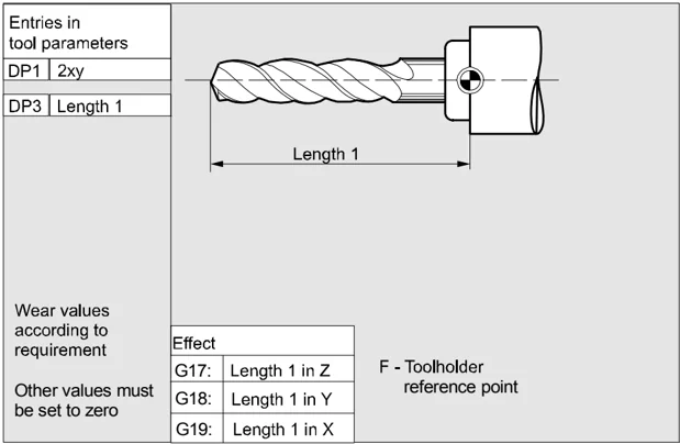
Required offset values for a drill
\begin{tabular}{|l|l|l|} \hline Entries in tool parameters & & \ \hline DP1 & 2xy & \ \hline DP3 & Length 1 & \ \hline Wear values according to requirement & Effect & \ \hline & G17: & Length 1 in Z \ \hline Other values must be set to zero & G18: & Length 1 in Y \ \hline & G19: & Length 1 in X \ \hline \end{tabular}
F - Toolholder reference point
©Siemens AG 2008 All rights reserved.

5 Parameters operating area 01/2008 5
5.1 Tool data
- Group type 4xx (grinding tools):
- 400 Surface grinding wheel
- 401 Surface grinding wheel with monitoring
- 402 Surface grinding wheel without monitoring
- 403 Surface grinding wheel with monitoring without tool base dimension for grinding wheel peripheral speed GWPS
- 410 Facing wheel
- 411 Facing wheel with monitoring
- 412 Facing wheel without monitoring
- 413 Facing wheel with monitoring without tool base dimension for grinding wheel peripheral speed (GWPS)
- 490 Dresser
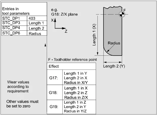
Offset values required by a surface grinding wheel
\begin{tabular}{|l|l|} \hline Entries in & \ tool parameters & \ \hline STC_DP1 & 403 \ \hline STC_DP3 & Length 1 \ \hline STC_DP4 & Length 2 \ \hline STC_DP6 & Radius \ \hline \end{tabular}
e.g. G18: Z/X plane X Z
Length 1 (X) Radius F - Toolholder reference point Length 2 (Y)
Wear values according to requirement Other values must be set to zero
\begin{tabular}{|l|l|} \hline Effect & \ \hline G17: & Length 1 in Y Length 2 in X Radius in X/Y \ \hline G18: & Length 1 in X Length 2 in Z Radius in Z/X \ \hline G19: & Length 1 in Z Length 2 in Y Radius in Y/Z \ \hline \end{tabular}
©Siemens AG 2008 All rights reserved.

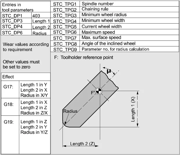
Required offset values for inclined grinding wheel with implicit monitoring selection

Required offset values for inclined grinding wheel with implicit monitoring selection
5 Parameters operating area
5.1 Tool data
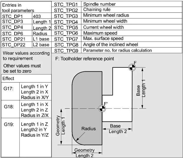
Required offset values of a surface grinding wheel without base dimension for GWPS
| Entries in tool parameters | STC_TPG1 | Spindle number | |
|---|---|---|---|
| STC_DP1 | 403 | STC_TPG2 | Chaining rule |
| STC_DP3 | Length 1 | STC_TPG3 | Minimum wheel radius |
| STC_DP4 | Length 2 | STC_TPG4 | Minimum wheel width |
| STC_DP6 | Radius | STC_TPG5 | Current wheel width |
| STC_DP21 | L1 base | STC_TPG6 | Maximum speed |
| STC_DP22 | L2 base | STC_TPG7 | Max. surface speed |
| STC_TPG8 | Angle of the inclined wheel | ||
| STC_TPG9 | Parameter no. for radius calculation |
Wear values according to requirement
Other values must be set to zero
| Effect | |
|---|---|
| G17: | Length 1 in YLength 2 in XRadius in X/Y |
| G18: | Length 1 in XLength 2 in ZRadius in Z/X |
| G19: | Length 1 in ZLength2 in YRadius in Y/Z |
F: Toolholder reference point

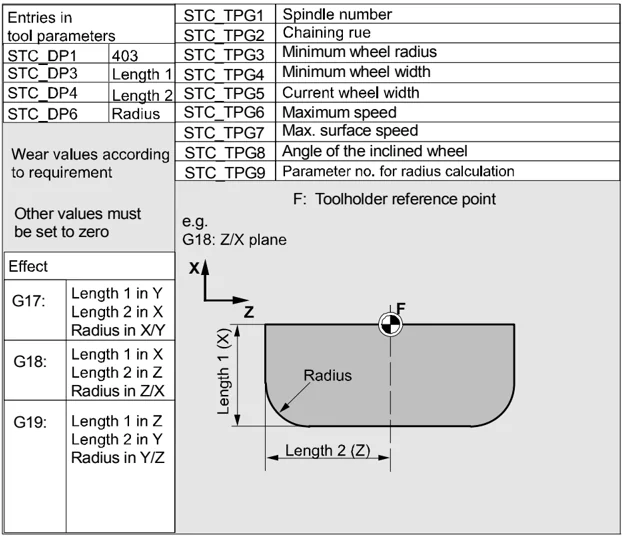
Required offset values of a facing wheel with monitoring parameters
| Entries in tool parameters | STC_TPG1 | Spindle number | |
|---|---|---|---|
| STC_DP1 | 403 | STC_TPG2 | Chaining rue |
| STC_DP3 | Length 1 | STC_TPG3 | Minimum wheel radius |
| STC_DP4 | Length 2 | STC_TPG4 | Minimum wheel width |
| STC_DP6 | Radius | STC_TPG5 | Current wheel width |
| STC_TPG6 | Maximum speed | ||
| STC_TPG7 | Max. surface speed | ||
| STC_TPG8 | Angle of the inclined wheel | ||
| STC_TPG9 | Parameter no. for radius calculation |
Wear values according to requirement
Other values must be set to zero
| Effect | |
|---|---|
| G17: | Length 1 in YLength 2 in XRadius in X/Y |
| G18: | Length 1 in XLength 2 in ZRadius in Z/X |
| G19: | Length 1 in ZLength 2 in YRadius in Y/Z |
F: Toolholder reference point
e.g.
G18: Z/X plane