6 "Program" operating area 6.8 Program simulation 01/2008 6
Additional information
-
Changes to the blank dimensions in the infeed axis (min or max) are automatically traced in the depths for color separation (min or max).
-
High values for the interpolator approximation accuracy cause increased distortion of the geometry representation (e.g. in details and rounded sections), but also reduce the amount of graphics memory required and increase the speed of the simulation.
Recommended settings
-
Recommended setting for group "simulation mode":
- .. in production
- Always reload tool "off" and store tool path "off"
- Block by block preparation "on" and wait with dwell times "off"
- .. in program mode (default setting)
- Always reload tool "on" and store tool path "on"
- Block by block preparation "off" and wait with dwell times "off"
- .. In training operation
- Always reload tool "on" and store tool path "on"
- Block by block preparation "off" and wait with dwell times "on"
- .. in production
-
The following settings are recommended for demonstrations with endless program loops (accelerated execution of simulation with reduced demands on the graphic memory):
- Always reload tool "off" and store tool path "off"
- Block by block preparation "on" and wait with dwell times "off"
and additionally:
- Blank "without model" (no memory used for graphic!)
- Or "without tool data", if representation of the tool center-point path (broken-line graphics) is sufficient.
If the blank model is active ("cuboid", "cylinder"), reduced graphic memory capacity might result, which, depending on the complexity of the part and model resolution set, could exhaust the graphic memory despite the save tool path setting "OFF".
6.8.3 Setting downtimes
Timing mode Setting timing for downtimes:
Settings. Downtime settings
OFF (default setting) Central timing does not include fixed downtimes or the processing of information for tabular "Time analysis".
Per program Central timing includes the elements listed in "Inclusion on" in the downtime analysis. The tabular "Time computation" is processed once per program in each case with M30, for example.
Per section with labels Effect as for "per program", only that processing of the tabular "time computation" is also performed when freely definable program labels occur or in combination with the path labels displayed in the simulation graphic (see ..\ Display and colors...\ Manage path labels).
Inclusion Enabling and setting of fixed downtimes in seconds
Tool changeON/OFF
- Definition of a fixed downtime for tool changes
Spindles ON/OFF
- Definition of a fixed downtime for main spindle and secondary spindle instructions
M functions ON/OFF
- Definition of a fixed downtime for M functions
H functions ON/OFF
- Definition of a fixed downtime for H functions
 Settings.
Load standard
Change default
Additional information
The default values can be modified according to the manufacturer's requirements if a valid password is entered. The new values are then globally valid for all new workpieces.
6 "Program" operating area
6.8 Program simulation
6.8.4 Display and colors
General attributes Setting the general properties of the simulation graphics:
Settings.
Display and colors...
Rapid traverse dashed line Alternatively, rapid traverse as a full line, as used for feedrate
Scale at edge of window Alternatively, as scale on the coordinate axes
Path labels Offers various possibilities under "Manage path labels" for displaying program labels, which have been inserted freely to identify specific points in the NC program (observe label syntax), as path labels at the corresponding point in the simulation graphics and then storing the associated graphic model in the buffer. Program labels can also be used to mark program sections, which can then be included by the central timing facility (see .. \ Downtime settings \ Timing mode \ In sections with labels). Path labels are specified in "Channel/spindle" as delimiter for section-by-section simulation in the same or different channels. You can save section models and use a search run to start again at that point without needing to repeat the preceding sections.
Use of color palettes
- Select a color with the cursor keys and press the Select key. The color of the focus frame changes.
- Use the cursor keys to select the object and press the Select key again. The object displays the selected color..

General colors In addition to the standard VGA colors, the color elements black and transparent to hide graphic elements are available in the color palette. Color selection option for background, blank, axis intersection, tool holder and tool edge.
6
6.8 "Program" operating area Program simulation
\begin{tabular}{p{0.3\textwidth} p{0.6\textwidth}} \textbf{Color palettes for tool path} & Two freely definable color palettes are available for tool paths for differentiating between \textbf{feedrate and rapid traverse movements}. In each color palette it is possible to differentiate between different \textbf{basic tool types} (without tools, drilling tools, milling tools, turning tools, threading tools, special tools), to allow differentiation for path visualization. \ \textbf{Channel assignment of color palettes} & One of the \textbf{two} tool type specific color palettes can be freely assigned to each of the required simulation channels. \ \textbf{Planes for color classification} & In the case of milling/drilling, the available colors are assigned to the defined \textbf{cutting depth range}. The default value is the thickness of the blank. \ Settings. & \ Load standard & \ Change default & \ \end{tabular}
Additional information
The default values can be modified according to the manufacturer's requirements if a valid password is entered. The new values are then globally valid for all new workpieces.
6.8.5 Section-by-section simulation
Function
A procedure in which first the individual sections of a program are optimized one after the other without collision consideration is the preferred method for testing part programs graphically.
Section by section simulation allows the user to go to the individual section of the program via reference points (using block search).
The reference points are always defined by path markers (program labels).
6 "Program" operating area 01/2008 6.8 Program simulation
Prerequisite:
- In order to manage path markers (program labels, e.g. MARKER1), they must be programmed at the required position in the program.
- Using the "Manage path markers" setting (Settings -> Display/Colors -> Manage path markers) you can decide whether – the path markers are to be displayed in the graphic and/or – the associated intermediate model is to be saved.
Settings. Display and colors...
Intermediate stages of the simulation model can be stored next to the path markers, allowing synchronized resumption of simulation without resetting the graphic that already exists. You can skip any sections that are already optimized.
Block search: In the menu "Block search" you can select the path marker you wish to jump to.
Search run
Additional information
- You can also load the machining list in menu "Channel/spindle" directly from the current workpiece via the "Program selection" softkey or from a JOB list.
6.8.6 Quick display in the simulation for mold making
Target The function offers quick display of machining paths, e.g. like those used by CAD systems. Generally these part programs are very large.
Any existing work offsets, G0, G2, G3 are not taken into account, only those axis paths resulting from G1 are displayed.
Characteristics of quick display
- Simulation for mold making is a standard function
- Switching between 2D and 3D is supported
- Rotation of workpiece in 3D view
- Representation in the various different planes
- Size scaling, zoom for the displayed workpiece
- Search via row number/string
- Search via machining block which traverses marked positions
- Progress bar
- Execution of part program blocks
- Distance measurement
- Can be interrupted by other operating areas/can be aborted
- The programs to be simulated can be executed from external drives
- The NC interpreter does not take part in the simulation.
6 01/2008
6.8 "Program" operating area Program simulation
Activating Operation for mold making simulation is available in the Program operating area if display machine data 9480: MA_SIMULATION_MODE is set to a value between 0 and 2. -1 Standard simulation 0 Selection between standard simulation/mold making G1 blocks via operation 1 Mold making only, G1 blocks 2 Automatic mode selection via program size. The limit value for the program size is specified in the display Machine data 9481: MA_STAND_SIMULATION_LIMIT.
Size scaling The following scaling settings are available: Zoom in, Zoom out and Automatic fit window. The automatic scaling function "Fit to size" uses the part program to take the largest expansion of the workpiece in the individual axes into account.
Search In the submenu Details, the search function displays the part program block whose machining path traverses the position (which was previously marked using the cursor keys or softkeys) in the workpiece representation.
First activate Block search then use the cursor keys or softkeys to move the cross-hair to the desired location. Press the input key to search for the required block and display it. The cross-hair must be positioned in the area of the displayed workpiece section.
In the submenu Edit you can choose whether to search for a block designated by a block number or a block which contains a specified string.
The search function will return the blocks that match the criteria and display them in the 2-line program section above the graphic display and highlight them.
Progress bar The message line shows the percentage value of the entire part program which is displayed in the graphic. Loading the workpiece graphic can be cancelled at any time by pressing the End softkey. Changing to a different operating area interrupts loading the graphic. When you return to the Program operating area, the loading process is continued.
6 "Program" operating area
6.8 Program simulation
Rotation In 3D representation the displayed workpiece can be rotated around any of the axes. The rotation instructions become active after you press Accept to confirm.
Distance measurement In the graphic display you can use the Mark point A and Mark point B softkeys to enter two markers at the positions you have set via the cursor keys. The direct path (space diagonal) between the points is output in the message line.
6.8.7 Simulation with external network drive
Function
With the SINDNC software, you can link your control to external network drives or other computers and use this facility for program simulation. It is possible to access files on network drives from a part program using the EXTCALL command.
- With EXTCALL, the drives in the network are also searched for subprograms (SPF only) if the program is called without a path. Subdirectories are not searched. The program will also be found if the search range is defined with the variable $SC_EXT_PROG_PATH or if a path to a file in the network - even in a subdirectory - has been defined.
- Programs in the network drives (with the extension MPF and SPF) can be simulated.
- If write access is set for a network drive, file DPWP.INI is created and the current directory is treated like a workpiece.
- If write access has not been set, a DPWP.INI is created for each network drive in the TEMP directory of the HMI irrespective of the current directory. In this case, the simulation settings are lost when the directory on the drive is changed.
6.8.8 Simulation for orientable toolholder
Function
You can process part programs for orientable toolholders using the simulation function. The following boundary conditions must be observed:
- The simulation distinguishes whether a toolholder Y has been activated for a tool x.
- Changes in the active toolholder are not detected. This is why the simulation uses the toolholder kinematic set initially for a tool y.
- Changes made after first activation (TCARR=x) are not considered.
- To use several toolholder kinematics for one tool y, create several identical tools with different toolholder settings.
- Inactive files are grayed out.
6.9 Managing programs
Function
To allow you to handle data and programs flexibly, you can organize, store and display them according to different criteria.
The memory is divided into:
- NC memory (main memory and program memory) containing the active system and user programs as well as all part programs for immediate execution and
- Hard disk
Programs can be exchanged between the program memory and hard disk.
Part programs may be stored either in the program memory of the NC or on the hard disk, but they are always executed from the program memory.
The "Load" and "Unload" functions are used to load or unload programs to or from the program memory (see Chapter 9.3 NC).
6 "Program" operating area
6.9 Managing programs
Program management
The programs and files are stored in different directories and can be administered in the Program and Services operating areas. The details are shown in the following overview:
Name of directories: Operating area:
- Subprograms Programs and Services
- Part programs Programs and Services
- Workpieces Programs and Services
- Definitions Services
- Comments Services
- Standard cycles Programs and Services
- Manufacturer cycles Programs and Services
- User cycles Programs and Services
The following diagram shows an example of directory contents:
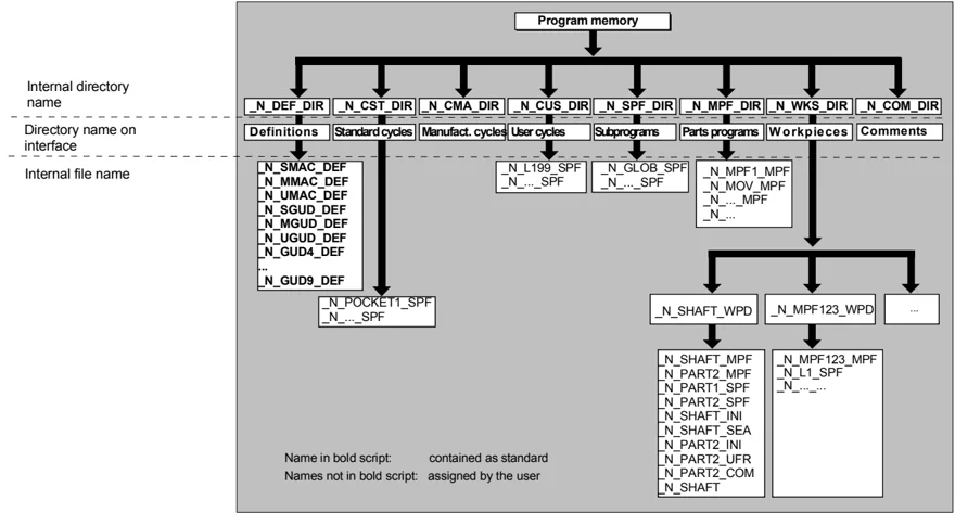
Internal directory name Directory name on interface Internal file name
Name in bold script: contained as standard Names not in bold script: assigned by the user
NC data types and directories
File types can be identified by the file name extension (e.g. .MPF).
name.MPF Main program name.SPF Subprogram name.TEA Machine data name.SEA Setting data name.TOA Tool offsets name.UFR Zero offsets/frames name.INI Initialization file name.COM Comment name.DEF Definition of global user data and Macros
6 01/2008 "Program" operating area 6.9 Managing programs 6
Please note that on the directories: comments \COM.DIR and definitions \DEF.DIR can only be accessed in the Services operating area via "Manage data".
6.9.1 New workpiece/part program
Function
The following subsection describes how you can select workpieces and part programs in a directory. A selected file can then be called and edited in the text editor.
Sequence of operations
Select workpiece/part program:
- Workpieces
- Part programs
- Subprograms
- User cycles
- Clipboard
Position the cursor in the directory on the desired file. For each file, the file name, file type, length, date of creation/last change are displayed. You can change the properties of the file display (see Section "Commissioning", "Settings" menu)
Call a part program: Use the cursor to select a program in the program overview and press the "Input" key. The text editor is displayed with the file you have selected.
You can now edit the part program.
6 "Program" operating area 01/2008 6
6.9 Managing programs
Open workpiece: The workpiece directory is opened and the programs it contains displayed on the screen.
Create workpiece directory You can set up various types of files such as main programs, initialization files, tool offsets, etc. in the new workpiece directory.
Sequence of operations
Workpieces The current overview of all workpiece directories appears on the screen.
New Input window "New" is opened. The cursor is located in the input field for the name of the new workpiece directory.
Enter the name of the new directory on the alphanumeric keyboard. Specify the created type in the data type field: WPF
If there are any templates for the specified data type in the Templates directory they are offered for selection. Press OK to confirm your selection. A new directory is set up in the workpiece overview. You are asked straight away for the name of the first part program and the Editor is opened. When creating a workpiece with New, all templates corresponding to your selection are only copied from the Templates\Siemens ... Manufacturer ... User directory to Commissioning\Settings\Templates if "No template" is selected in the Templates selection field.
If a template is proposed for the workpiece, then all elements assigned to it such as job list, part program, subprograms are transferred to the new workpiece in compliance with the template and its language-specific elements.
6.9.2 Create programs/data in a workpiece directory
Function
This section explains how you can create a new file for a part program or workpiece.
Sequence of operations
The current overview of the workpiece directories stored on the NC appears.
Position the cursor on the required workpiece and open it.
An overview will be displayed listing the data and programs that have already been created in the workpiece directory. If no data is available, the program overview is blank.
A dialog box appears when you press the "New" softkey. Enter the new file name.
You can also enter the corresponding file type using the "Insert key". For instance, the following file types are possible:
6 "Program" operating area 01/2008 6
6.9 Managing programs
 Create part programs in the part program/subprogram directory: You can set up main programs and subprograms by opening directories "Part programs" and "Subprograms".
Press the "New" softkey to display a dialog window in which you can enter the names of the new main programs and subprograms. The matching file type is automatically assigned in this case.
Number of workpieces
- A maximum of 100,000 files can be stored in the data manager.
- The number of files per directory must not exceed 1,000 (or per workpiece directory for workpieces *.WPD).
- The maximum size of editable files is 56 MB.
6.9.3 Saving setup data
Function
With the "Save setup data" softkey, you can store all the active data belonging to a particular workpiece located in the working memory of the NC. The data are stored for each channel under the same name under a workpiece.
Additional information
"Save setup data" can be disabled by the manufacturer using the protection levels.
Sequence of operations
Workpieces
The current overview of all workpiece directories appears on the screen.
Place the cursor on the workpiece directory or workpiece in which you want to store the workpiece-specific data.
Save setup data
The input window "Store workpiece data" is opened when you select "Save setup data". In this input window you can select the workpiece data that you wish to save.
6
"Program" operating area
6.9 Managing programs
E.g., you can select the following data types:
- R parameters (RPA)
- Work offset (UFR)
- Setting data (SEA)
- ...
If a job list exists, it is used as the basis for the save procedure.
Save With the "Save" softkey, you store the workpiece data of the selected data types in the relevant workpiece directory.
If a job list exists in this workpiece directory, the data for all the channels involved in the workpiece are automatically backed up. For this, the main program selected at the beginning is searched for each channel in the job list. The data are then backed up according to the data types selected under its name.
Load standard With the „Load Standard softkey you can load the default settings for input window "Save workpiece data".
Note: Default settings are always supplied by SIEMENS.
Set standard Press this softkey if you want to define your own defaults in the input window.
6.9.4 Selecting a program to be executed

Function Workpieces and part programs must be selected for machining/execution before you press the NC Start key.
Sequence of operations
Select a program: Use the cursor keys to select a program in the
Part programs program overview, e.g., part programs, and
▼ then press the "Selection" softkey.
Selection The program name is displayed in the "Program name" window at the top right.
Cycle Start You can start the part program by pressing "NC Start".

6 "Program" operating area 6.9 Managing programs 01/2008 6
Select a workpiece: A workpiece directory can be selected for machining in the currently active channel.
Use the cursor keys to select the workpiece
in the workpiece overview and then
press the "Selection" softkey.
- If only one main program (MPF) exists in this directory, it is automatically selected for execution. If the directory contains several main programs, the main program with the same name as the directory is automatically selected for execution (e.g. if you select workpiece SHAFT.WPD main program SHAFT.MPF is automatically selected). The program name is output along with workpiece information in the "Program name" window at the top right. You can start the part program you have selected by pressing the "NC Start" key.

- If an INI file of the same name exists (e.g., SHAFT.INI), it will be executed once at the first part program start after selection of the part program. Any additional INI files are executed in accordance with machine data 11280 $MN_WPD_INI_MODE.
When you select workpiece directory SHAFT.WPD you implicitly select program SHAFT.
If a .JOB file with the same name is stored in the workpiece directory, it is executed immediately.
See also Chapter "Job list" and "Sequence of operations" "Executing job list".
Find path for program call
If the call path is not explicitly specified in the part program when a subprogram (or an initialization file) is called, the called program is located according to the predefined search strategy.
Case 1: When a subprogram is called by name with specification of the data type ("identifier" or "extension"), e.g. SHAFT1.MPF the system searches through the directories in the following sequence:
- Current directory / name.type Workpiece/standard directory MPF.DIR
- /SPF.DIR / name.type Global subprograms

6
"Program" operating area
6.9 Managing programs
- /CUS.DIR/name.type User cycles
- /CMA.DIR/name.type Manufacturer cycles
- /CST.DIR/name.type Standard cycles
Case 2: When a subprogram is called by name without specification of the data type ("identifier" or "extension"), e.g. SHAFT1 the system searches through the directories in the following sequence:
- Current directory / name Workpiece/standard directory MPF.DIR
- Current directory / name.SPF
- Current directory / name.MPF
- /SPF.DIR/name.SPF Subprograms
- /CUS.DIR/name.SPF User cycles
- /CMA.DIR/name.SPF Manufacturer cycles
- /CST.DIR/name.SPF Standard cycles
References
/PGA/, Programming Guide Advanced
Machine manufacturer
see the machine manufacturer's information.
Preconditions:
- A main program (MPF) in the workpiece directory is selected "NC Start" was activated $MN_WPD_INI_MODE=0: The INI file with the same name as the selected workpiece is executed. For example, if SHAFT1.MPF is selected, SHAFT1.INI is executed when "NC Start" is pressed. (Behavior as with previous software versions) $MN_WPD_INI_MODE=1: All files of type INI, SEA, GUD, RPA, UFR, PRO, TOA, TMA and CEC which have the same name as the selected main program are executed in the specified sequence.
- The main programs stored in a workpiece directory can be selected and processed by several channels.
References
Commissioning Manual HMI-Advanced (IM4)
6 "Program" operating area
6.9 Managing programs
6.9.5 Loading/unloading a program
Function
Programs can be stored in the NC memory ("Load") and then erased from it again ("Unload") after execution. This prevents the NC memory from being overloaded unnecessarily.
Sequence of operations
Position the cursor on the program to be loaded.
The highlighted program is loaded from the hard disk to the NC memory.
The selected program is deleted on the hard disk.
See also Chapter "Job list".
If enable is set "(X)", the program can be executed.
The highlighted program is unloaded from the NC memory to the hard disk.
The selected program is deleted in the NC memory.
Additional information
Programs which have been loaded to the NC memory are automatically marked with an "(X)" (in the "Loaded" column) in the program overview.
If the file is located both on the HMI and the NC, the identifier "X" is only removed when the files are no longer identical.
If the files have different time stamps or are of different lengths, the identifier is "!X!".
If you want to "load/unload" a workpiece directory and a job list with the name of the directory exists in the directory, then this job list is processed.
If no job list exists, all the files in that directory are loaded/unloaded (working memory of NC might overflow!).

6.9.6 Manage programs
Function
You can reorganize programs and files in the "program overview" using the "Manage programs" function:
- New... Select new workpiece/part program
- Copy/insert Copy directories and files
- Delete Delete workpieces and files
- Rename Rename file and data type
- Modify enable Enable each workpiece/part program in the program overview or not.
Sequence of operations
In the "Program overview" dialog box, press the "Manage programs..." horizontal softkey. Active functions are indicated by softkeys in which the text appears on a black background. Inactive softkeys are grayed out.
Press the "New ..." softkey to select a new workpiece or part program. The "interactive programming" window is opened and the cursor is positioned in the input field for the name of the new directory. Enter the new name of the program. The file type is assigned automatically. The display also shows whether or not a template exists.
Default setting
You can choose between interactive programming and the text editor. The more frequent choice, file editing with "interactive programming", is the default setting. Alternatively, you can use the text editor to edit files.
Confirm your input with the "Input" key.
This key cancels the entire operation.
Press the "OK" softkey to load the workpiece or part program you have just selected. You can then use the program management functions available in the horizontal softkey bar.
6 "Program" operating area
6.9 Managing programs
6.9.7 Copying/inserting
Function
This section tells you how to copy files from a source directory to an existing destination directory.
Except when overwriting workpieces, the files are copied from the NC program memory or from the hard disk to: Hard disk (HD) or NC memory (NCK) or Buffer or Diskette (is specified as network drive) or Network drive (Network1 to Network4)
All directories with the exception of compile cycles can be copied to the destinations specified above.
Copy/insert
Several selected files or workpieces can be copied together in a single operation.
When copying workpieces: All associated files are copied too. All files with the workpiece name are automatically renamed to the new workpiece name. Files from the Workpieces directory can only be overwritten in another directory. All workpiece files of type .WPD can be copied from one drive to any other drive.
Specify the file name and file type
Copying from network drives: All data types known to the HMI are set according to their extension and the data management scheme. A dialog box is opened for files with an unknown extension. You can enter or change the name and file type - up to 3 characters are permissible.
If a file of the same name is already stored on the hard disk or in the NC memory, a dialog box prompts you to change the name and file type. If the source file and destination are identical, the existing file is not overwritten. The copy operation can either be canceled or an integer is added to the existing file name in ascending order.
6 01/2008
"Program" operating area
6.9 Managing programs
6
Manage program
▼ Copy
Paste OK
SELECT
Sequence of operations
The "Manage programs" softkey must be pressed.
Position the cursor on the file that you want to copy and press the "Copy" softkey.
The file is marked as the source for copying. An existing file is either overwritten or, if the name or file type was changed, saved with the new name.
Please note that several "Save as" dialogs give you the chance to change the file name and file type before the files are overwritten. The "Save as" dialog box appears if the "All without query" vertical softkey was not pressed and:
- you have pressed "Insert" for the first time.
- the file cannot be created in the current directory.
- the file already exists.
Press the "Insert" softkey, enter a new name and confirm with "OK".
When you insert a file in a workpiece directory, you can change its file type with the "Toggle" key. The file types are automatically adjusted in the global part program and the global subprogram directory.
Additional information
- Only files can be stored in a workpiece directory but not other workpiece directories.
- If the target specified is incorrect an error message is output.
- If a workpiece directory is copied, all the files that it contains are copied at the same time.
- If the files of a workpiece directory are copied to a new directory, all the files with the same directory name are renamed to the new workpiece directory name.
- If a job list with the name of the directory exists, all the instructions in that job list are renamed.
This function only applies to the "Program" operating area. When you copy under "Services", the names remain unchanged. See also section "Renaming".
6 "Program" operating area 01/2008 6
6.9 Managing programs
Query dialogs "Save as"
In the "Commissioning" operating area, press the "HMI" \rightarrow "System settings" \rightarrow "Query" softkeys to specify that a query dialog box is to appear before files are overwritten. Otherwise, the files are overwritten without prompting or a copy is created.
V ertical softkeys for "Save as"
All without prompt Press the "All without prompt" softkey if all existing files in the current directory are to be created with new names without a "Save as" dialog. All files for which the original file type cannot be created are automatically converted to the specified data type.
Skip file Press the "Skip file" softkey if the copy operation is to be continued with the next file.
Abort This key cancels the entire copy operation.
OK An existing file is either overwritten or, if the name or file type was changed, saved with the new name. The "OK" softkey is disabled if you have to enter a new name. The "Data type" input field accepts 0 to 3 letters.
Query dialogs
Copy file from hard disk:
- The file exists on hard disk and is overwritten when you select "OK" if the name/data type is to remain unchanged!
- The file exists on hard disk. When you select "OK" a copy is created if the name/file type is to remain unchanged!
Copy file from NC memory:
- The file exists on the NCK and is overwritten when you select "OK" if the name/data type is to remain unchanged!
- The file exists on the NCK. When you select "OK" a copy is created if the name/file type is to remain unchanged!
Copy a workpiece:
- The workpiece already exists. When you select "OK" a copy of the workpiece is created if a new name is not specified!
Copy a directory:
- The directory already exists. When you select "OK" the contents are overwritten if a new name is not specified!
- The directory already exists. When you select "OK" the contents are overwritten if the directory with a fixed data type cannot be changed.
Copy a file of data type main program (MPF):
- The file cannot be created at this location under its original "main program" data type!
6.9.8 Deleting
Function
This section explains how you can delete workpieces or files.
Sequence of operations
The "Manage programs" softkey must be pressed.
Position the cursor on the workpiece or the file you want to delete.
Delete several files: If you wish to select several files, position the cursor on the first file, press the "Select" key and then position the cursor on the last file. The files you have selected are highlighted.
The prompt "Do you really want to delete the file?" appears.
Confirm your input.
Additional information
- You can only delete programs that are not currently running.
- If you want to delete a workpiece directory, make sure that none of the programs it contains is currently selected.
- If a workpiece directory is deleted, all the files that it contains are deleted at the same time.
6 "Program" operating area 01/2008 6
6.9 Managing programs
6.9.9 Renaming

Function
As regards files, you can alter their name as well as the associated file type.
Sequence of operations
Manage program
The "Manage programs" softkey must be pressed.
Position the cursor on the file you want to rename.
Rename
The "Rename" dialog window opens.
Enter the new name.
When you rename a workpiece, you can also change the file type with the "Toggle key". File types are matched automatically in the part program and subprogram directories.
SELECT
There are two ways of renaming files:
- Renaming the workpiece directory
- Renaming a directory in the workpiece directory
Rename a workpiece directory:
When you rename a workpiece directory, all the workpiece files under that directory that have the same name as the directory are renamed. If a job list with the name of the directory exists, the instructions in that job list are also renamed.
Comment lines remain unchanged.
Examples:
Workpiece directory A.WPD is renamed B.WPD:
All files with the name A.XXX are renamed as B.XXX, i.e. the extension is retained.
If a job list called A.JOB exists, it is renamed as B.JOB.
If this job list contains instructions of file A.XXX and these are located in this workpiece directory, then that file is also renamed B.XXX.


6 01/2008 "Program" operating area 6.9 Managing programs 6
If job list A.JOB contains an instruction LOAD/Work.DIR/A.WPD/A.MPF it is renamed as LOAD/Work.DIR/B.WPD/B.MPF However, if a job list contains the instruction LOAD/MPF.DIR/A.MPF or LOAD/Work.DIR/X.WPD/A.MPF the files are not renamed.
Rename a directory in the workpiece directory: If you rename the files in the workpiece directory, all files with the same name but a different extension are renamed. Exception: If a job list of the same name exists in the directory, then this one is not renamed.
6.9.10 Enabling

Function
The program overview indicates whether a workpiece or part program is enabled. This means that: it may be executed (e.g., because it has already been tested) by the control after you select the "Program selection" softkey and the "NC Start" key. If you set up a new program, it is automatically enabled.

Sequence of operations
To set the enable for a program or abort it, position the cursor on the desired workpiece or part program in the program overview.
Press the "Change enable" softkey. A cross indicating "Enable issued" appears behind the workpiece or part program.
Change enable
(X) Enable issued (program can be executed)
( ) No enable issued (program must not be executed)
SINUMERIK 840Di sl/840D sl/840D Operating Manual HMI-Advanced (BAD) - 01/2008 Edition 6-353
6 "Program" operating area
6.9 Managing programs
Additional information
- The system checks whether a program may be executed when the program is called (after selection via operator input or from part program). If you want it to be enabled, you must enable it beforehand. (See also Chapter 6 "Changing properties of file/directory/archive")
6.9.11 Protocol
Function
If you are working on the hard disk, the following data are included in the log:
- Name of program currently being executed (execution from external source)
- Names of previously executed programs
- Prompts: e.g. "Do you really want to delete job?"
- Error list: Names of previously executed programs in which an error occurred.
Sequence of operations
Press the "Log" softkey. The "Job log for programs" window opens.
Depending on the status of the current program run, the following functions can be executed by means of the vertical softkeys (e.g. when prompt "Really delete?" is displayed in the "Query" window):

- The program currently being executed is deleted.
- All programs in the current job list are deleted.
- The program currently being executed is not deleted.
- The program currently being executed is aborted.

6.10 Accessing an external network drive/computer
Function
With the SINDNC software, you can link your control to external network drives or other computers. The following conditions apply:
- The SINDNC software is installed.
- The computer or drive which you want to link up to is accessible/enabled.
- A connection to the computer/drive has been established.
- The softkeys to select the drive/computer connection have been configured by making entries in the file "MMC.INI".
See: Commissioning Manual HMI-Advanced (IM4)
Sequence of operations
You can access network drives 1 to 3 from level 0 of the Program operating area using horizontal softkeys 4 to 6. With the "ETC" key, you can access network drive 4 from level 2 using horizontal softkey 7. The cycle directories are also stored at level 2 and are assigned to softkeys 4 to 6.
When you press a softkey, e.g., "Drive F.:" or "R4711" the Explorer appears on the screen with the data of the external drive, e.g. "Drive F" or of computer "R4711".
You can perform the following operations (in addition to paging) via the vertical softkeys in the Program operating area:
- Copy/insert files (not directories) from network drives in the data manager. A type conversion cannot be performed according to the destination directory.
- Copy/insert from the data manager or a network drive to network drives. The files are set up on the network drive using DOS naming conventions. The file name used in the data management (source) is maintained.
- Deleting files (no directories) on the network drives
- Simulation
- Editing files (find/go to, mark block, edit) if write access to the drive is enabled.
- Files on the network drives can be simulated. This applies to files with the identifier MPF or SPF.
6 "Program" operating area 01/2008 6
6.10 Accessing an external network drive/computer
Additional information
- If the drive/computer is not connected or enabled, the message "No data available" is displayed.
- A root directory can only be selected as the destination for copying to a network drive if "." is displayed.
- In the Machine operating area, only files with an HMI-compatible name can be selected for "Exec. f. hard disk" (i.e. up to 27 characters, no special characters, no blanks).
- In operating area Program, the functions Copy, Insert, and Delete can only be applied to files without blanks in their name.
- The file name is displayed as it would be in the Windows Explorer with a long file name, but only up to 25 characters are displayed.
Services operating area
- 7.1 Services main screen ........ 7-359
- 7.1.1 Reading-in data ........ 7-362
- 7.1.2 Reading-out data ........ 7-363
- 7.1.3 Displaying the log ........ 7-364
- 7.2 Managing data ........ 7-366
- 7.2.1 New file/new directory ........ 7-367
- 7.2.2 Loading and unloading ........ 7-367
- 7.2.3 Copying and inserting ........ 7-368
- 7.2.4 Deleting ........ 7-369
- 7.2.5 Changing properties ........ 7-370
- 7.3 Data selection ........ 7-373
- 7.3.1 Special directories and memory areas ........ 7-376
- 7.3.2 Data on the hard disk ........ 7-377
- 7.4 Transfer display MD from HMI Embedded ........ 7-380
- 7.5 V.24 interface ........ 7-382
- 7.5.1 Parameterizing the V.24 interface ........ 7-382
- 7.5.2 Using the V.24 interface ........ 7-386