6.7 Free contour programming
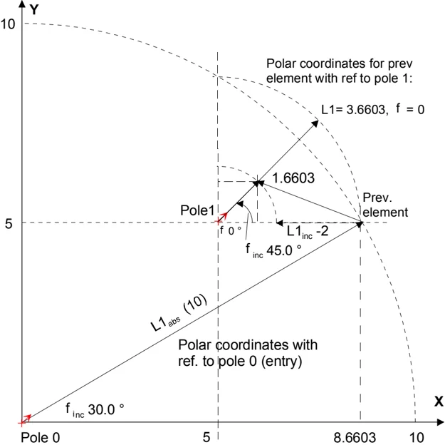
Pole change example
Pole: $X_{Pole}$ = 0.0, $Y_{Pole}$ = 0.0 (Pole 0)
End point: $L1_{abs}$ = 10.0 \phi_abs = 30.0° Calculated Cart. Coordinates $X_{abs}$ = 8.6603 $Y_{abs}$ = 5.0
New pole: $X_{Pole1}$ = 5.0 $Y_{Pole1}$ = 5.0 (Pole 1) Calculated polar coord. Predecessor $L1_{abs}$ = 3.6603 \phi_abs = 0.0°
Next point: $L1_{inc}$ = -2.0 \phi_inc = 45.0°
Absolute polar coordinates for current element $L1_{abs}$ = 1.6603 \phi_abs = 45.0° Calculate Cartesian coordinates $X_{abs}$ = 1.1740 $Y_{abs}$ = 1.1740
6 "Program" operating area 01/2008 6
6.7 Free contour programming
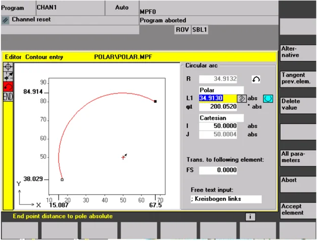
Example: input circular arc, polar
You require a counter-clockwise arc to travel from the starting point X67.5 Y80.211 around the center point I=50, J=50 (according to the pole) and the radius 34.913 to the end point with an absolute polar angle of 200.052 degrees.
The inputs for the circular arc are as follows:

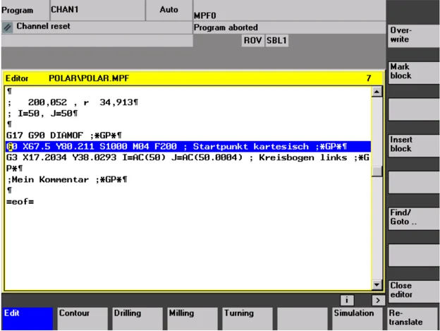
The code created in the part program is as follows:
References
/PG/, Programming Manual Fundamentals: "Programming a circle with polar coordinates"
6-306 ©Siemens AG 2008 All rights reserved.
6.7.7 Support for contour programming
Function
When you input parameters, you can call up a help screen using the Info key which graphically represents the parameters you are entering. The help screen that appears depends on the cursor position in the parameter display.
The help screen is placed over the graphic display.
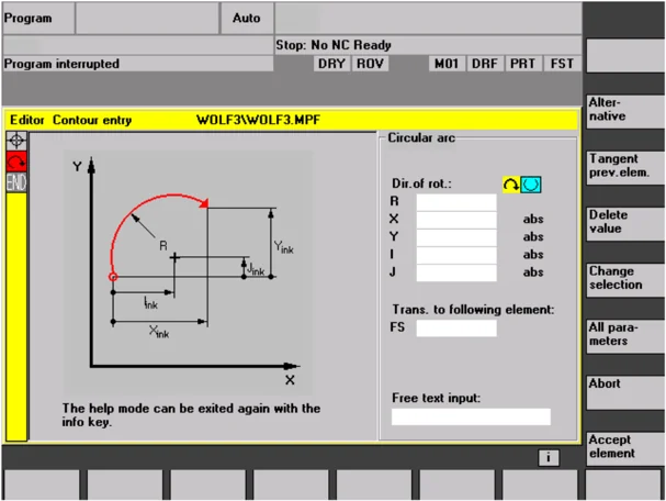
If you press the Info key again the help screen is closed and the graphic display is activated once again. The help screens displayed correspond to the selected coordinate system. The axis identifiers are derived from the current geometry axis names.
Help screens are displayed for the following entries:
- Starting point
- Straight vertical line
- Straight vertical line, angle entry field
- Straight horizontal line
- Straight horizontal line, angle entry field
- Straight line in any direction
- Straight line in any direction, angle entry field
- Circle
- Circle, angle entry field
- Radius/chamfer
6 "Program" operating area 01/2008 6.7 Free contour programming
6.7.8 Parameter description of the contour elements straight line/circle
\begin{tabular}{|l|l|} \hline Parameters & Contour element "Straight line" \ \hline X absolute & Absolute end position in X direction \ \hline X incremental & Incremental end position in X direction \ \hline Y absolute & Absolute end position in Y direction \ \hline Y incremental & Incremental end position in Y direction \ \hline L & Length of straight line \ \hline \alpha1 & Pitch angle with reference to X axis \ \hline \alpha2 & Angle to preceding element; tangential transition: \alpha2=0 \ \hline Transition to next element & Transition element to next contour is a chamfer (FS) \ & Transition element to next contour is a radius (R) \ & FS=0 or R=0 means no transition element \ \hline \end{tabular}
\begin{tabular}{|l|l|} \hline Parameters & Contour element "Circle" \ \hline X absolute & Absolute end position in X direction \ \hline X incremental & Incremental end position in X direction \ \hline Y absolute & Absolute end position in Y direction \ \hline Y incremental & Incremental end position in Y direction \ \hline \alpha1 & Starting angle with reference to X axis \ \hline \alpha2 & Angle to preceding element; tangential transition: \alpha2=0 \ \hline \beta1 & End angle with reference to X axis \ \hline \beta2 & Angle of aperture of circle \ \hline Direction of rotation & In clockwise or counter-clockwise direction \ \hline R & Radius of circle \ \hline I & Position of circle center point in X direction (abs. or incr.) \ \hline J & Position of circle center point in Y direction (abs. or incr.) \ \hline Transition to next element & Transition element to next contour is a chamfer (FS) \ & Transition element to next contour is a radius (R) \ & FS=0 or R=0 means no transition element \ \hline \end{tabular}
Machine manufacturer The names of the identifiers (X or Y ...) are defined in the machine data where they can also be changed.
6-308 ©Siemens AG 2008 All rights reserved.
6.7.9 Programming examples for freely programming a contour
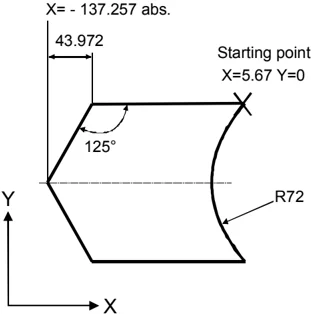
Example 1
Workpiece drawing of contour
Starting point: X=5.67 abs., Y=0 abs., machining plane G17
The contour is programmed in a counter-clockwise direction.

| Element | Softkey | Parameters | Comment |
|---|---|---|---|
| 1 | ← → | All parameters, α1=180 degrees | Observe angles in help screen! |
| 2 | ↖ ↗ ↘ ↙ | X=-43.972 inc, all parametersX=-137.257 abs.α1=-125 degree | Definition of coordinates in X in "abs." and in "inc."Observe angles in help screen! |
| 3 | ↖ ↗ ↘ ↙ | X=43.972 incα1=-55 degree | Definition of coordinates in X in "inc"Observe angles in help screen! |
| 4 | ← → | X=5.67 abs | |
| 5 | ↘ ↙ | Clockwise direction of rotation,R=72, X=5.67 abs.., Y=0 abs..,Select dialog |
6 "Program" operating area
6.7 Free contour programming
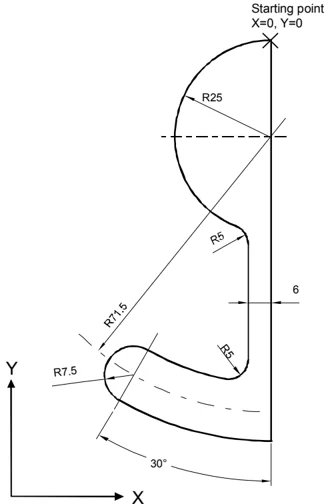
Example 2
Starting point: X=0 abs., Y=0 abs., machining plane G17
The contour is programmed in the clockwise direction with dialog selection.
For this contour it is advisable to display all parameters via the "All parameters" softkey.
Workpiece drawing of contour

| Element | Softkey | Parameters | Comment |
|---|---|---|---|
| 1 | ▲●▼ | Y=-104 abs. | |
| 2 | ↻●↻ | Clockwise direction of rotation, R=79, I=0 abs.,Select dialog, all parameters, β2=30 degrees | |
| 3 | ↻●↻ | Clockwise direction of rotation, tangent to preced.R=7.5, all parameters, β2=180 degrees | |
| 4 | ↻●↻ | Counterclockwise direction of rotation, R=64, X=-6 abs.,I=0 abs.,Make dialog selection, make dialog selectionTransition to following element: R=5 | |
| 5 | ▲●▼ | All parameters, α1=90 degrees,Transition to following element: R=5 | Observe angles in help screen! |
| 6 | ↻●↻ | Clockwise direction of rotation, R=25, X=0 abs., Y=0abs. I=0 abs., make dialog selection, make dialog selection |
©Siemens AG 2008 All rights reserved.
6.7 Free contour programming
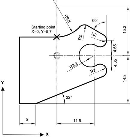
Example 3
Starting point: X=0 abs., Y=5.7 abs., machining plane G17
The contour is programmed in a clockwise direction.
Workpiece drawing of contour

| Element | Softkey | Parameters | Comment |
|---|---|---|---|
| 1 | Counterclockwise direction of rotation, R=9.5, I=0 abs., make dialog selection, Transition to following element: R=2 | ||
| 2 | α1=–30 degree | Observe angles in help screen! | |
| 3 | Clockwise direction of rotation, tangent to preced. R=2, J=4.65 abs. | ||
| 4 | Counterclockwise direction of rotation, tangent to preced. R=3.2, I=11.5 abs., J=0 abs., make dialog selection, make dialog selection | ||
| 5 | Clockwise direction of rotation, tangent to preced. R=2, J=–4.65 abs., make dialog selection | ||
| 6 | Tangent to preced. α1=–158 degrees, Y=–14.8 abs., α2=0 degrees | Observe angles in help screen! | |
| 7 | All parameters, L=5, make dialog selection | ||
| 8 | Y=5.7 abs. |
6 "Program" operating area
6.7 Free contour programming
\begin{tabular}{|l|l|l|} \hline 9 & \leftrightarrow & X=0 abs. \ \hline \end{tabular}
©Siemens AG 2008 All rights reserved.
6.7.10 Cycle support
The following technologies:
- Drilling
- Milling
- Turning
are provided with additional support in the form of pre-defined cycles, which must then be parameterized.
References Programming Guide Cycles
Settings Define the following values in the "Editor Settings" window:
- Horizontal paging ON/OFF
- Display hidden lines ON/OFF
- Time interval for Automatic Save When you set Automatic Save, you can also set the time intervals at which text must be saved automatically (applicable only to files on hard disk). If a value ≠ 0 is entered, the "Save file" softkey is not displayed. If the value 0 is entered, automatic save is not performed.
- Automatic numbering ON/OFF A new block number is automatically inserted on every new line. If you wish to assign block numbers to an existing program, use the "Renumber" function.
- Number of first block
- Incrementation of block numbers (e.g. 1, 5, 10)
The following settings are possible for contour programming:
- Last line Each time you complete a program step in contour programming you can insert text in the last line (e.g., "End of contour").
Additional information
- The coordinate system and the technology to be used are set via the machine data; see Commissioning Manual HMI Advanced.
- Edited programs are automatically enabled after saving.
6.8 Program simulation
Function
Simulation Drilling/milling and Complete turning operations
Simulation selection
Graphical simulation is implemented as a self-contained process. The simulation can be selected directly from the program overview or from the ASCII editor after selection of a part program in the "Program" operating area.
Commissioning
You can perform simulation without any special commissioning. The simulation can be started with default data in accordance with the set turning or milling technology.
Using the "Match data" function, selected data can be loaded from NC to the simulation environment and are then available for the simulated programs just like during program execution in the NC. Providing the correct password is used, additional functions and optimizations (e.g. accelerate simulation run-up) can be performed.
This is described in the Commissioning Manual HMI Advanced, Chapter Match simulation data. In addition, the default values listed in the simulation interface can be adapted to suit the machine manufacturer’s requirements.
Technology types
- Drilling/milling
- Complete turning operations
- Workpiece-specific technology assignment through local "DPWP.INI" file
Superimposing principle
The simulation results of several part programs in succession (e.g. for multilateral machining during milling, internal/external machining during turning, multi-slide machining, etc.) can be superimposed on an overall display of the same blank (see machining list in Channel/Spindle softkey). The finished part results from the sequential interaction of all the simulated part programs. The direct simulation of several part programs (simultaneously) is not possible. The range of effectiveness (channel, spindle, tool, sequence) of the currently selected part program is visible in the status line on the lower edge of the simulation window.
6 01/2008 "Program" operating area 6.8 Program simulation 6
ASCII editor link After deliberate interruptions (simulation STOP or Single-block in the main simulation menu) or on alarms, you can use the "Correct program" softkey to open the program in the editor at the point of interruption. For interruptions within protected cycles the program pointer is positioned at the line with the corresponding subprogram call. If changes are made in the editor, simulation is returned to the last active section (intermediate model if available).
Additional information
- The integrity of the simulation data (programs, subprograms, tool data, etc.) is assured by systematic time-stamp evaluation for all loading operations.
- NC language labels (e.g. WAIT2: WAITM...) ...) programmed to identify particular points in the program, can be inserted in the simulation graphic as path labels. You can simultaneously initiate the generation of intermediate models at these points in the program (see "Manage settings\Display and colors...\Manage path labels").
- The model used is based on a 3D Cartesian model.
- The software limit switches are not evaluated during the simulation because no reference point approach is performed. Even an entry in the DPSIM.TEA file is not taken into account.
References DPSIM.TEA is used to adjust machine data which the user may have defined incorrectly in the INITIAL.INI. For a detailed description please refer to: Function Manual Basic Functions, Interactive Programming (D2)

6 "Program" operating area 01/2008 6
6.8 Program simulation
6.8.1 Using the simulation function
Sequence of operations
Main menu After a program or workpiece is selected, the Simulation softkey is made available.
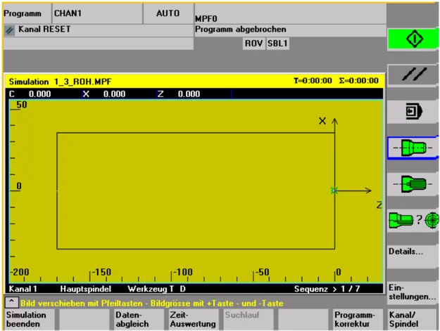
Turning technology main screen
When you select a simulation via a workpiece, first the machining list from the Channel/spindle menu (see below) is displayed. Press OK to exit the menus. The main menu is now displayed.
Horizontal main menu
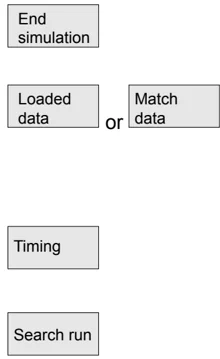
End simulation Terminate simulation. Return to the program overview or ASCII editor. You need the correct password for this.
Loaded data or Match data With the correct password you can match the simulation data with the corresponding "NC active data" (setup data, tool data, machine data, cycles). See "Match data" menu
Timing Tabular evaluation of the execution times for the current simulation session (see Chapter "Downtime settings")
Search run The function "Search run" can be used to start the simulation selectively for specific sections.
6.8 "Program" operating area
Program simulation
Edit program
Activate the ASCII editor from the current simulation interruption status (cursor position synchronized with graphic).
Return to simulation with "Close editor"
Channel / spindle
Program-specific channel and spindle assignments (activate processing list in combination with the overlay principle).
See menu "Channel/spindle"
Vertical main menu
- Simulation START or simulation STOP
(program-by-program in conjunction with the machining list) - Simulation RESET
The previous execution result is discarded for the program at hand and a polymarker is displayed. - Simulation single block ON/OFF - SINGLE BLOCK
(status display in header SBL1, SBL2 or SBL3)
Technology-specific workpiece views
- Milling: Top view
Turning: External view (front) - Milling: Default top view
Turning: Full section, frontal and front view
(free selection under "Details...") - Milling: 3D view or wire model
Turning: Default half-section, frontal Front and wire model
(free selection under "Details...")
Details
Select status-dependent detail menu (active view, alarm status)
Settings.
Select user and vendor-specific setting menus
in RESET or STOP state or
in RUN state display current simulation override






6 "Program" operating area 01/2008 6
6.8 Program simulation
Notes
- On simulation START and program change, any 3D view currently displayed is automatically deselected and replaced by a technology-specific default view.
- If you repeat machining simulation START after end of program M2/M30 of the last program to be simulated, the simulation channels are usually RESET and the simulation graphic reset if no machining list has been activated with the "Channel/spindle" softkey.
- If the machining list under "Channel/spindle" is activated, the overlay principle takes effect for the listed programs, where global reset in combination with a simulation START is only activated after a query on the last M2/M30.
- New selection or reselection of one of the listed workpiece views is implicitly linked to automatic screen size adjustment.
- In the case of "turning" technology, drills and milling cutters in the G18 plane can only be displayed as polymarkers (cross symbol) in the side views. Only the tool center point path without the tool body is displayed. The tool is visible on the front face view (G17) or on peripheral surface processing (G19).
"Details..." menu
Standard horizontal
Assuming 2 window views with no alarm status:
- Default when milling: "Top view and front view"
- Default when turning: "Half-section and wire model"
With 2 window views only:
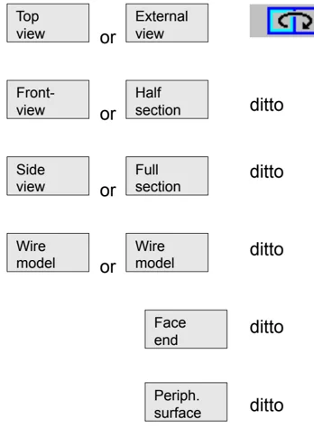
Free selection of the different views in window activated by means of
Milling \hfill Turning
Top \hfill External view \hfill or \hfill view
Front- \hfill Half view \hfill or \hfill section \hfill ditto
Side \hfill Full view \hfill or \hfill section \hfill ditto
Wire \hfill Wire model \hfill or \hfill model \hfill ditto
Face \hfill ditto end
Periph. \hfill ditto surface

6.8 Program simulation
“Details...” menu
Standard vertical
- "Top view" or "top view and front view" for milling
- "Wire model" (3D without tool data) for milling
- All views for turning
Tool paths on/off or Tool paths on/off Activate/deactivate representation of the tool center point path. Deactivation also deletes any tool paths from the current model that have already been stored (default setting: tool paths on).
 With 2 window views only: Select active window.
Possible in the same manner with "TAB" or "NEXT WINDOW (V06.02.13 and higher).
Front view... Conditionally with 2 window views: "Front..." depending on type of view active (horizontal selection) same meaning as "from above..." or "from left..."
Rear view... Conditionally with 2 window views: "Rear..." depending on type of view active (horizontal selection) same meaning as "from below..." or "from right..."
Fit to size Automatic screen resizing relative to the window activated with . Also possible with the "ENTER" or "INPUT" key.
Zoom... Show window pane border in active window (Size can be altered with "+" - and "-" keys, position can be altered with cursor keys.)
<< Return to main simulation menu
-
Menu "Details ........ " 3D vertical
"3D view" (3D with tool data) for milling, not effective for turning simulation
 Standard 3D view, orientation top/front
 3D view, orientation top/left, rotated clockwise by 90 °.
3D view, orientation top/right, rotated clockwise by 90 °.
 3D view, orientation bottom/front, inclined towards top
"Program" operating area
6.8 Program simulation
Fit to size
Automatic screen size adaptation
Also possible using the "ENTER" or "INPUT" key.
Zoom...
Show window pane border in active window
(Size can be altered with "+" - and "-" keys, position can be altered with cursor keys.)
<<
Return to main simulation menu
-
Menu Alarm "Details ........ " vertical
Assuming an alarm status during simulation, independent of the view currently active
[I]
Reset POWER ON alarms of simulation. The simulation is terminated and loaded again.
[□]
Reset RESET alarms of simulation. The simulation interpreter is reset. The simulation can be started again.
[□]
Reset CANCEL alarms of simulation. The simulation can be continued.
The simulation process is terminated. A load operation is necessary before the simulation is selected again.
End simulation
Open the menu bar corresponding to the active workpiece view "Details..." (standard or 3D) from the alarm state. The simulation alarms remain active.
Details view...
Return to main simulation menu
<<
Return to main simulation menu
Additional information
- Simulation alarms are only messages of the simulation interpreter and have no direct association with the current NCK machining status on the machine tool.
- If more than one simulation alarm is pending, you can show or hide the complete alarm list with the "toggle" key. You can select an alarm with the "cursor" keys.
- If you press the information key "i" the online help with an explanation of the selected alarm is displayed.</F>
- Program sequences which cannot be interpreted in simulation contexts only and only then trigger an alarm (e.g. in user cycles because the relevant PLC data and signals are not available in the



6
"Program" operating area 6.8 Program simulation
simulation interpreter), must be jumped conditionally in the corresponding NC program with evaluation of system variable $P_SIM during the simulation (..IF $P_SIM GOTOF label). The components relevant to simulation (e.g. tool change position and M switching functions for tool change in tool change cycles, etc. cannot be skipped, they must be executed.
- The simulation does not evaluate events set by MD 20108, which lead to program activation.
Menu "Match data" vertical
Correct password and NC components are prerequisite for using Match data to load data selected in the NC to the simulation environment. The data is then available for the simulated programs just like during program execution in the NC. (Matched data see data management \DP.DIR\SIM.DIR)
Loaded data The loaded files are displayed. User programs, user cycles, standard cycles, manufacturer cycles and base data.
Compare setup data The selected data is loaded into the simulation environment from the NC. After editing NC data, a new data synchronization operation must be performed. On the other hand, the response of the NC to modified data can be simulated in advance by editing the data within the simulation environment.
Compare tools The tool data for all channels is loaded to the simulation environment and copied to the file TO_INI.INI.
Compare mach. data The machine data and active definition files are loaded to the simulation environment and copied to the file INITIAL.INI.
Compare cycles The cycles which have already been loaded into the simulation are replaced by cycles with more recent time stamps.
<< Return to main simulation menu.
6 "Program" operating area 6.8 Program simulation 01/2008 6
Additional information
- If no Match data operation has yet taken place (and the NCK component is installed), a request is automatically issued in the form of a message when the simulation is initialized. The user is automatically informed of modifications to tool data.
- The working cycles are loaded from the part program once on the first call and remain active for all subsequent simulation sessions.
- With the "Match cycles" softkey you can load updated cycles with a new timestamp into the simulation. Cycles with access protection are always reloaded, irrespective of the timestamp. The Match data process only needs to be repeated if changes have been made to the cycles.
- It is recommended to set MD11210=0 "Match all machine data".
"Channel/spindle" menu vertical
Only accessible from RESET or STOP status
The screen shows the current execution list for the selected part programs.
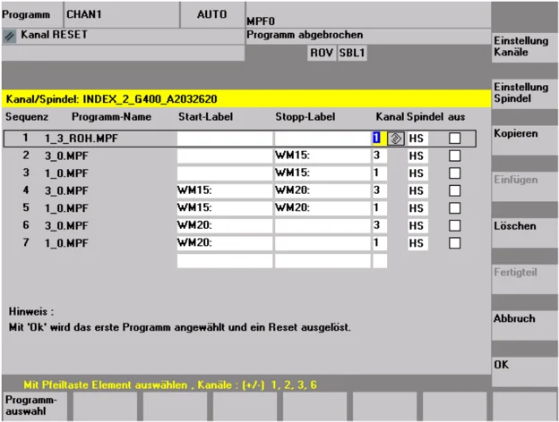
Sequence Simulation sequence of programs Program name List of programs
6 01/2008
6.8 "Program" operating area Program simulation 6
Start label Path label from which a program is simulated. If this is not specified, simulation takes place from program start.
Stop label Path label up to which a program is simulated. If this is not specified, simulation takes place to program end. (See also "Multi-channel, section by section program simulation".)
Channel Processing channel in the SIMNCK interpreter
Spindle Turning: MS main spindle, CS counterspindle, var variable controlled via NC vocabulary word. (Milling: currently unused)
Off Skipping The designated section/program is not simulated in the current session.
Channel settings Leads to the manufacturer-specific channel settings (subject to correct password).
Milling Constant machine arrangement
Turning Machine arrangement in front or behind turning center.
S pindle settings Leads to the manufacturer-specific spindle settings (subject to correct password). currently unused
Milling
Drehen Defines longitudinal offset for main spindle and counterspindle, longitudinal mirroring on/off, NC keyword definitions for spindle switchover.
Copy Copy selected line of machining list to clipboard.
Paste Insert the machining list line that was copied/deleted from the clipboard at the position of the selected line (the selected line is moved down one row).
Delete Delete the selected line from the machining list
6 "Program" operating area 6.8 Program simulation 01/2008 6
Abort Return to main simulation menu: Modifications to the current machining list are not saved
OK Return to main simulation menu: Modifications to the current machining list are saved and activated with the information displayed
Additional information
-
To activate the machining list after a workpiece selection, it must be selected explicitly at least once with the "Channel/spindle" softkey. The list is displayed implicitly every time a program is subsequently selected from the same workpiece directory so that it can be added to as required. It only makes sense to define a simulation sequence using the machining list "Channel/spindle" provided if the overlay principle for part machining is used (i.e., when the simulation result of several part programs in succession is to be viewed at a single blank). In such cases, it is especially important to also follow the instructions at the bottom of the dialog. These may contains lines for which an intermediate model has already been created, a special status display. By selecting such a line in the machining list you can place the simulation directly on the associated intermediate model again.
-
If individual programs are simulated, the machining list default produces the correct simulation sequence even if the menu item "Channel/spindle" is not selected (and therefore without applying the overlay principle).
-
With the correct password you can define manufacturer-specific default setting values with "Change default" under menu items "Channel settings" and "Spindle settings", which then apply globally for all new workpieces.
Channel / spindle
6.8.2 Simulation settings
"Settings..." menu
Only accessible from the RESET or STOP state of the simulation (e.g., single block mode) Other settings can only be displayed/hidden if you enter a valid password via the "Options" softkey.
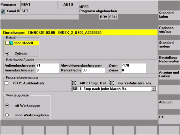
Load standard Load manufacturer-specific default settings (See data management: \DP.DIR\SIM.DIR\SIMINI_M.COM for milling or SIMINI_T.COM for turning and differential files in the \USER directory.
Options on/off or Options on/off Display/hide optional setting parameters in the current window, (Initial setting is options off)
Change default The default values can be modified according to the manufacturer's requirements if a valid password is entered. The changes to the manufacturer-specific default set values in files "SIMINI_M.COM" and "SIMINI_T.COM" are used as differential parameters in the files "DPMWP.INI" and "DPTWP.INI" in the \USER directory and taken into account for all new workpieces.
Downtime settings With the correct password, you can set the desired computation mode for secondary times and selectively define estimated secondary times for the NC functions T, S, M and H.
Settable parameters: See Chapter "Downtime settings"
The input screen has been changed to enable selection between the machine data and an individual tool change time (as previously).
6 "Program" operating area 01/2008 6
6.8 Program simulation
If the machine data 10190 ($MN_TOOL_CHANGE_TIME) is set and greater than 0, the "Downtime setting" offers a range of options via additional buttons:
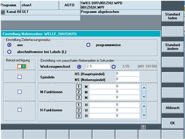
The user can either enter an individual time for the tool change or select the displayed value for the machine data. The default is the value entered by the user. This can be preset via the entry in the file SIMINI_T.COM (for turning) or SIMINI_M.COM (for milling) in the \DP.DIR\SIM.DIR data manager.
[Sim] DP_SIMNCK_MD10190=0 ;Default: value 0 = tool change time is set by user (see DP_SIMNCK_TOOLCHANGETIME) ; 1 = tool change time from MD10190 ($MN_TOOL_CHANGE_TIME)
If MD10190 is not set or the value is equal to 0, the formula remains as it was previously.
Display and colors... The specified display and color properties for the simulation can be modified according to the manufacturer's requirements if a valid password is entered. Settable parameters: See Chapter "Display and colors"
6-326 © Siemens AG 2008 All rights reserved.
6.8 "Program" operating area Program simulation 6
Abort Return to main simulation menu. The old settings before the setting screen was selected are retained.
OK Return to main simulation menu. The modified settings are saved and activated immediately.
Basic "Settings..."
Blank
- Milling: without model (display area), cuboid (blank dimension cuboid), cylinder (blank dimension cylinder).
- Turning: without model (display area), cylinder (blank dimension cylinder) and active processing diameter for peripheral surface.
Active view
- Milling: X-Y, Z-X, Y-Z (for "Cuboid" and "Without model" only)
- Turning: Z-X always defined, cannot be changed
Blank dimension cuboid
- Minimum and maximum dimensions for each axis
Program control
- SKP: Skip blocks (10 skip levels are available)
- M01: Programmed STOP 1 or
- M101: Programmed STOP 2 taken into account
- Single block mode:
- SBL1: Stop after each machine function
- SBL2: Stop after each block
- SBL3: Stop in cycle
- Display all blocks or only traversing blocks
Tool data (source) NC active data
The tool offsets are used in accordance with the active NC (Match tool data \TO_INI.INI) and the tool path is simulated with graphic tools. With technology turning the cutter radius is not modeled. The tool radius compensation is evaluated. Tools that are not interpreted are displayed as polymarkers.
With tool
HMI data, local TOA data, global SPF file, tool match data from data management \DP.DIR\SIM.DIR\TO_INI.INI
Default tools
Evaluation only with milling/drilling if no TO_INI.INI (Match tool data) is present and tool management option not active. The tool diameter can be parameterized (providing access is enabled via a valid password) if ON is activated under the Options settings. The tool radius compensation is evaluated.
Without tool data
The tool path is simulated with a polymarker. No evaluation of tool radius compensation i.e. broken-line graphics with compensation value D0.
6 "Program" operating area 6.8 Program simulation 01/2008 6
Additional information
- In order to reduce the input effort when the blank type is repeatedly changed, the blank dimensions and the display area are compared internally when the settings are saved.
- A suitable image of the NC-active data INITIAL.INI and TO_INI.INI under DH\DP.DIR\SIM.DIR is required for simulation with the option "Tool monitoring". Default settings for the tool management are taken from the supplementary tool data ..\mmc2\dp\sim\to_addon.ini. Tools which are not loaded in the active magazine image (from TO_INI.INI) can therefore be called during simulation if necessary.
- In simulation "without tool data", using standard cycles results in the representation of the final contour derived from the available cycle parameters.
- Simulation "without model" and/or "without tool data" both limits the required graphic memory and increases the simulation speed.
Optional "Settings..."
Other settings can only be displayed/hidden if you enter a valid password via the Options softkey.
Options on/off
Depths for color classification
Depth range across which the available VGA system colors for displaying depth information are distributed (default range = blank thickness). The rounding inaccuracy in defining depth of color is $10^{-3}$ units.
Default values
- Tool diameter: Tool diameter used for milling simulation with default tool (end mill/drill).
- IPO mm or inch: Approximation precision of simulation interpolator in mm or inches depends on actual measuring system.
- F override %. Setting the simulation feed
% setting options: %1 to %500 (from V06.12.13 < 10 %)
- Increment of 10 with "+" or "-" key
- Increment of 50 with "Cursor right" or "Cursor left"
- Max/Min value with "Cursor up" or "Cursor down".
- Default value 100 with "Toggle" key

6 01/2008
6.8 "Program" operating area Program simulation
Display options
- Actual position: Display hide actual value of simulated channel axes (Note: TRANS, ROT, SCALE and MIRROR are not taken into account in the actual value display).
- NC block: Activate/deactivate display of current NC block
- Machining time: Activate/deactivate display of the calculated machining time in the header of the basic simulation window (T = calculated machining time (from the programmed feedrates) = machining time + sum of all estimated down times).
Simulation mode
- Always reload tools
- In position "on" (default setting), all the necessary tool data are reloaded on each program change.
- In position "off", tool data are only reloaded if required, if the timestamp is altered (automatic query). Otherwise, the existing tool environment is not changed.
- Save tool path
- In position "on" (default setting), all the tool paths in the simulation sequence are visualized and stored temporarily in the model for future display (zoom, etc.).
- In position "off", the resulting tool paths are visualized once and not stored temporarily in the model. When the display is subsequently manipulated (e.g., Zoom +), the tool paths are lost.
- Block-by-block processing
- In position "on", discontinuous path processing, but largely accelerated (reduced number of IPO interpolation points, for example, only at block end points on straight lines).
- In position "off" (default setting), largely continuous path processing (constant distance between interpolation points depending on the IPO setting).
- Waiting for dwell times
- In position "on", program instructions with dwell times cause real dwell times in the simulation.
- In position "off" (default setting), the dwell is suppressed in the simulation and the dwell times are only taken into account in time calculations.