1 Introduction
1.1 Product overview
1.1 Product overview
The SINUMERIK controller is a CNC control system (Computerized Numerical Control) for machine tools.
You can use the CNC control system to implement the following basic functions in conjunction with a machine tool:
- Creation and adaptation of part programs
- Execution of part programs
- Manual control
- Reading in and reading out of part programs and data
- Editing of data for programs
- Displaying and troubleshooting alarms
- Editing of machine data
- Setting up of communication links between 1 or more operating units (m) or 1 or more NCs (n) (m:n, m operating units and n NCK/PLC units).
Operating areas
The basic functions are grouped in the following operating areas in the control (in gray boxes):

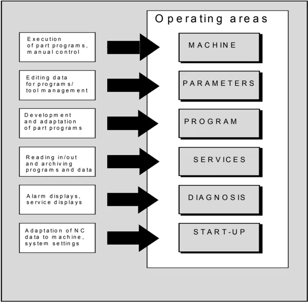
The user can call up all the functions via the user interface.
The user interface consists of:
- Display units such as screen, LEDs, etc.
- Control elements such as keys, switches, handwheels, etc.
Read Chapter 2 "Operation" carefully before proceeding with further chapters.
All subsequent chapters are written on the assumption that you have done so!
1.2 Handling information
Caution
The operator panel front/machine control panel may only be opened by trained personnel for servicing purposes.
Danger
Never open the operator panel front/machine control panel unless the power supply has been disconnected! Failure to comply could result in fatal injury!
Warning
Electronic components inside the operator panel/machine control panel can be destroyed by electrostatic discharge if they are handled incorrectly.
Before operating any of the control elements on this operator panel front: Please first read the explanations supplied in this documentation!
1 Introduction 01/2008 1
1.3 Switching on/switching off the control
1.3 Switching on/switching off the control
Function
Switching on
A variety of methods can be employed to switch on the power supply to the control system or to the whole plant.
Machine manufacturer
Please follow the machine manufacturer's instructions!
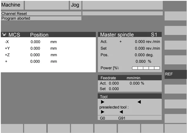
After the control has been switched on, the "Reference point approach" display or another main screen programmed by the machine manufacturer will appear.

Switching off
Please follow the instructions below for switching off the control or the entire system!
Machine manufacturer
Please follow the machine manufacturer's instructions!
1.3 Switching on/switching off the control
Sequence of operations
When you press the "Area switchover" key, operating areas are displayed on the horizontal softkey bar and operating modes are displayed on the vertical softkey bar. You can use this key to go to the area menu bar from any location in the menu hierarchy if you wish to select another operating mode or a different operating area.
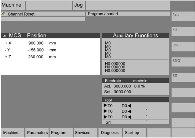
By pressing the "Area switchover" key twice, you can toggle between the operating areas last selected, e.g. between the "Parameters" and "Machine" areas.
1 Introduction 01/2008 1.3 Switching on/switching off the control
Notes
1-22 © Siemens AG 2008 All rights reserved.
Operator Components/Operating Sequences
- 2.1 Operator panel front ........ 2-24
- 2.1.1 Keys on the operator panel front ........ 2-24
- 2.1.2 Standard full keyboard ........ 2-29
- 2.2 Machine control panel (MCP) ........ 2-30
- 2.2.1 EMERGENCY STOP button ........ 2-31
- 2.2.2 Operating modes and machine functions ........ 2-31
- 2.2.3 Feedrate control ........ 2-33
- 2.2.4 Spindle control ........ 2-35
- 2.2.5 Key-operated switch ........ 2-36
- 2.2.6 Program control ........ 2-37
- 2.3 SINUMERIK HT 8 ........ 2-39
- 2.4 Screen layout ........ 2-42
- 2.4.1 Displaying the control states ........ 2-42
- 2.4.2 Global machine status display ........ 2-43
- 2.4.3 Program control display ........ 2-48
- 2.5 General operating sequences ........ 2-50
- 2.5.1 Program overview and program selection ........ 2-50
- 2.5.2 Changing the menu window ........ 2-51
- 2.5.3 Selecting a directory/file ........ 2-52
- 2.5.4 Editing inputs/values ........ 2-53
- 2.5.5 Confirm/cancel input ........ 2-54
- 2.5.6 Edit the part program in the ASCII editor ........ 2-55
- 2.5.7 Switching over the channel ........ 2-61
- 2.5.8 Packet calculator ........ 2-62
- 2.6 Calling the help function ........ 2-63
- 2.6.1 Editor help ........ 2-65
- 2.6.2 Quick help for program commands ........ 2-66
- 2.6.3 Extended help for program commands ........ 2-69
- 2.7 Job list ........ 2-70
- 2.7.1 Syntax description for job lists ........ 2-72
- 2.7.2 Example of a job list with two-channel 1:1 links ........ 2-75
- 2.7.3 Example of a job list with multi-channel m:n links ........ 2-76
- 2.7.4 “Execute job list” operating sequence ........ 2-77
- 2.7.5 Re-naming workpieces with job lists ........ 2-79
- 2.7.6 Copying workpieces with job lists ........ 2-80
- 2.7.7 Archiving workpieces with job lists in the case of M:N ........ 2-80
2 Operator Components/Operating Sequences
2.1 Operator panel front
2.1 Operator panel front
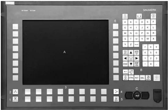
Example In this example, the OP 012 SINUMERIK operator panel front is used to illustrate the operator components, which are available for operating the SINUMERIK control and machine tool.
Properties The OP 012 operator panel front with 12.1" TFT color display with a resolution of 800 x 600 pixels (SVGA) features a 59-key membrane keypad as well as 2 x (8 + 2) horizontal and 2 x 8 vertical softkeys and a built-in mouse.
A Display B Alphanumeric keypad Correction/cursor keys C Mouse and mouse keys
1 Machine area key 2 Recall (return) 3 Softkey bar (horizontal) 4 ETC key (menu extension) 5 Area switchover key 6 Softkey bar (vertical)
2.1.1 Keys on the operator panel front
Keys on the operator panel front The elements of the operator panel keyboard and the symbols used to represent them in this manual are shown and explained below. The keys marked with an * correspond to the key symbols in US layout.
Softkeys Keys to which functions are assigned by means of a menu bar displayed on the screen.
- It is possible to access further menu levels via the horizontal softkeys in any operating area. Each horizontal menu item has a vertical menu bar/softkey assignment.
- The vertical softkeys are assigned functions for the currently selected horizontal softkey.
A function is called up by pressing one of the vertical softkeys. The assignments of the vertical softkey bar can change if further subsidiary functions are classified under a function.
2 01/2008 Operator Components/Operating Sequences 2.1 Operator panel front 2

Parameter
Softkey (horizontal or vertical): This key symbol indicates that you must have selected an operating area or a menu item or have already performed certain functions before you are able to execute the function described in the relevant section.
Machine area key Direct branch to the "Machine" operating area.
Recall key Return to the higher-level menu. Recall closes a window.
ETC key Expansion of the horizontal softkey bar in the same menu.
Area switchover key You can call the main menu from any operating area by pressing this key. Pressing the key twice in succession changes from the current operating area to the previous one and back again. The standard main menu branches into the following operating areas:
- Machine
- Parameters
- Program
- Services
- Diagnostics
- Commissioning
Shift key Switches between functions on keys with double assignment.
Switch over channel In a configuration with several channels, it is possible to switch between channels (switch from channel 1 through to channel n). When a "Channel menu" is configured, all existing communication links to other NCUs plus the associated channels are displayed on softkeys.
(See Section "Switch over channel")
2 Operator Components/Operating Sequences
2.1 Operator panel front
 Acknowledge alarm key
By pressing this key, you can acknowledge the alarm marked by this Cancel symbol.
 Information key
This key displays explanatory information about the current operating status (e.g. support for programming, diagnostics, PLC, alarms).
The letter "i" displayed in the user response line indicates that information is available.
 Window selection key
If several windows are displayed on the screen, it is possible to make the next window the active one using the window selection key (the active window has a thicker border).
Keyboard input e.g. the page keys, is possible only in the active window.
 Cursor up
 Cursor down
 Cursor to the left
 Cursor to the right
 PAGE DOWN
You "scroll" down by one display.
In a part program, you can "scroll" the display down (to end of program) or up (to start of program).
 PAGE UP
You "scroll" up by one display.
With the page keys you scroll the visible/displayed area of the window that is active. The scroll bar indicates which part of the program/document/... is selected.
 Backspace
Delete characters from right
Space character (Blank)
©Siemens AG 2008 All rights reserved.

2 01/2008 Operator Components/Operating Sequences 2.1 Operator panel front 2
Selection key
- Selection key for values set in input fields and selection lists labeled with this key symbol.
- Activate/deactivate a field:
☑ = active ☐ = not active ◉= active ○= not active
Multiple option button (you can select several options or none)
Single-option button/option (only one option can be active at a time)
Edit key / undo key
- Switch over to edit mode in tables and input fields (in this case, the input field is in insert mode) or
- UNDO function on table elements and input fields (the value is not validated when you exit a field using the edit key; instead it is reset to the previous value = UNDO).
End of line key
- With this key, the cursor is moved to the end of the line in the page opened in the editor.
- Rapid positioning of the cursor on a group of related input fields.
- Has same effect as Tab key.
Delete key The setting in a parameterization field is deleted. The field remains blank.
Input key
- Accepts an edited value
- Opens/closes a directory
- Opening a file
Tab key
Ctrl key
Alt key
Tool offset Takes you directly to the tool offset
2 Operator Components/Operating Sequences
2.1 Operator panel front
Program management program overview A program can be opened in the text editor.
Interrupt Takes you directly to the Alarms screen
User key Can be configured by the customer
Notes
The keys marked with an * also have a function in conjunction with ShopMill/ShopTurn.
"PROGRAM" hardkey
For this function to work, at least one recently edited program must be found with sufficient read rights. The program must not be already open in either a simulation or any other application. Actions such as load, copy, select, etc. must not be in progress and the part program must not be running on the NC. In the above cases, the operation is denied with alarms 1203xx.
Press this hardkey in any operating area to reopen and display the part program or file last edited in the Program operating area:
- If you are already in the Program operating area and the editor is open, the program you last edited is displayed.
- If you are in any other operating area, and the editor is open, you jump back to the editor in the Program operating area and the most recent editor status is displayed.
If the editor is not open:
- If you are in another user application, you jump back to the Program operating area and the editor is opened with the program you last edited.
©Siemens AG 2008 All rights reserved.
2 01/2008 Operator Components/Operating Sequences 2.1 Operator panel front 2
2.1.2 Standard full keyboard
A full standard keyboard can be connected. However, a machine control panel is required in addition to this keyboard.
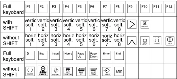
The special function keys of the operator keyboard can also be used with the full PC keyboard. The following table shows how the horizontal and vertical softkeys and the special keys for the operator panels are mapped onto the PC keyboard keys:
Softkey assignment
\begin{tabular}{|l|c|c|c|c|c|c|c|c|c|c|c|c|} \hline Full keyobard & F1 & F2 & F3 & F4 & F5 & F6 & F7 & F8 & F9 & F10 & F11 & F12 \ \hline with SHIFT & vertic soft. 1 & vertic soft. 2 & vertic soft. 3 & vertic soft. 4 & vertic soft. 5 & vertic soft. 6 & vertic soft. 7 & vertic soft. 8 & $>$ & M MACHINE & & \ \hline without SHIFT & horiz soft. 1 & horiz soft. 2 & horiz soft. 3 & horiz soft. 4 & horiz soft. 5 & horiz soft. 6 & horiz soft. 7 & horiz soft. 8 & \wedge & MENU SELECT & CHANNEL & HELP \ \hline Full keyboard & 5 & Esc & Insert & Home & Page Up & Page Down & Enter & End & & & & \ \hline without SHIFT & SELECT & ALARM CANCEL & INSERT & NEXT WINDOW & PAGE UP & PAGE DOWN & INPUT & END & & & & \ \hline \end{tabular}
The following table shows how the hardkeys of the MF 2 keyboard on the PC are mapped onto the keys for the operator panels:
Hardkey assignment
\begin{tabular}{|l|c|c|c|c|c|c|c|c|c|c|c|} \hline Hardkey & Hard-key 1 & Hard-key 2 & Hard-key 3 & Hard-key 4 & Hard-key 5 & Hard-key 6 & Hard-key 7 & Hard-key 8 & & & \ \hline MFII with SHIFT & F11 & & & & & F12 & F10 & & & & \ \hline MFII with-out SHIFT & & & & & & & & F10 & & & \ \hline MFII-Num Block & & END & Page Down & Home & Page Up & & & & & & \ \hline operator keyboard & ML Position & PROGRAM & OFFSET & PROGRAM MANAGER & ALARM & CUSTOM & M MACHINE & MENU SELECT & & & \ \hline \end{tabular}
Caution The full standard keyboard does not meet the requirements (EMC) of a SINUMERIK control. For this reason, it can be used only for installation and service purposes.
Additional information Since the English version of Windows is used in the control, the keyboard language is English. A different keyboard language cannot be set.
2 Operator Components/Operating Sequences
2.2 Machine control panel (MCP)
2.2 Machine control panel (MCP)
i Actions on the machine tool, for example traversing the axes or program start, can only be initiated via a machine control panel.
The machine tool can either be equipped with a standard machine control panel from SIEMENS (ordering data option) or with a specific machine control panel from the machine-tool manufacturer.
The following description applies to the 19" machine control panel supplied by SIEMENS (= standard). If you are using another machine control panel, please consult the operating instructions of the machine-tool manufacturer.
The standard machine control panel is equipped with the following control elements:
- EMERGENCY STOP button
- Operating modes (with machine functions)
- Incremental mode
- Program control instructions
- Direction key with rapid traverse override
- Spindle control
- Feedrate control
- Key-operated switch
 Machine control panel for turning machines
 Machine control panel for milling machines
©Siemens AG 2008 All rights reserved.
2.2.1 EMERGENCY STOP button
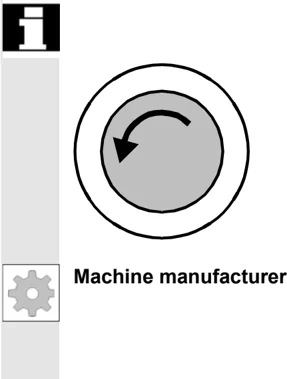
EMERGENCY STOP button
Press this red key in emergency situations:
- if life is at risk
- When there is a danger of the machine or workpiece being damaged.
As a rule, when operating the EMERGENCY STOP button, all drives are brought to a standstill with max. braking torque.
Machine manufacturer For details of other or additional responses to an EMERGENCY STOP: Please read the information supplied by the machine tool manufacturer!
2.2.2 Operating modes and machine functions
Modes of operation
The active mode is signaled and confirmed by the associated LED, which lights up.
The keys marked with an * correspond to the key symbols in US layout. If you press a "Mode key", the corresponding mode is selected if permissible, and all other modes and functions are deselected.

JOG (Jogging) Axis travel in jog mode via:
- Continuous motion of the axes using the direction keys, or
- Incremental motion of the axes using the direction keys, or
- Handwheel

MDA (Manual Data Automatic) Control of machine through execution of a block or a sequence of blocks. The blocks are entered on the operator panel front.

Automatic Control of machine through automatic execution of programs.
2 Operator Components/Operating Sequences
2.2 Machine control panel (MCP)
I nc keys
You can activate the Inc functions in conjunction with the following modes:
- "JOG" mode
- "MDA/Teach-in" operating mode

Inc VAR (Incremental feed VARiable) Incremental mode with variable increment size (see operating area Parameters, Setting data).
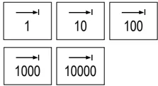
Inc (Incremental feed) Incremental mode with fixed increment size of 1, 10, 100, 1,000, 10,000 increments.
A machine data code defines how the incremental dimension is interpreted.
Machine functions
Teach In Creation of programs in interactive mode with the machine in "MDA" mode.
Repos Repositioning Reposition, re-approach contour in "JOG" mode.
Ref Approaching a reference point Approach the reference point (Ref) in "JOG" mode.
2
Operator Components/Operating Sequences 2.2 Machine control panel (MCP) 2
2.2.3 Feedrate control

Feedrate rapid traverse override (feedrate override switch)
Control range: 0% to 120% of programmed feedrate. In rapid traverse, the 100% value is not exceeded. Settings, 0%, 1%, 2%, 4%, 6%, 8%, 10%, 20%, 30%, 40%, 50%, 60%, 70%, 75%, 80%, 85%, 90%, 95%, 100%, 105%, 110%, 115%, 120%

Feed stop
If you press the "Feed stop" key:
- Execution of the current program is stopped
- The axis drives are brought to a standstill under control, The associated LED lights up as soon as feed stop has been accepted by the control and The following appears in the header (program control display): FST (= Feed Stop) Example: – In "MDA" mode, an error is detected during execution of a block. – A tool change is to be carried out.

Feed start
If you press the "Feed start" key:
- The part program is continued in the current block,
- The feedrate is accelerated to the value specified by the program,
- The associated LED lights up as soon as feed start has been accepted by the control.
2 Operator Components/Operating Sequences 01/2008
2.2 Machine control panel (MCP)
Axis keys (for turning machines):
+X +Z -X -Z
Press these keys to traverse the selected axis (X ... Z) in the positive direction.
Press these keys to traverse the selected axis (X ... Z) in the negative direction.
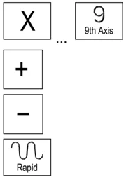
Axis keys (for milling machines):
 X ... 9 9th Axis
+
 X ... 9 9th Axis
+
Rapid
Select the axis (X ... 9) for traversing
in the positive direction by pressing the "+" key or
in the negative direction by pressing the "-" key.
Rapid traverse override If you press this key together with key "+" or "-", the axis moves in rapid traverse mode.
Machine manufacturer
- The specified increments and control range apply to standard machines.
- Increments and control range can be modified by the machine tool manufacturer to suit specific applications.
- Feedrate/rapid traverse feedrate and the values for the feedrate override positions (if the feedrate override switch is also active for rapid traverse) are defined in the machine data (see the information supplied by the machine manufacturer).
 WCS MCS
MCS/WCS You can switch between the machine and workpiece coordinate systems in the Machine operating area using softkeys (MCS)/(WCS) or the corresponding key on the machine control panel.
©Siemens AG 2008 All rights reserved.
2.2.4 Spindle control

Spindle override (spindle speed override switch)
The rotary switch with latch positions allows you to increase or decrease the programmed spindle speed "S" (equivalent to 100%). The set spindle speed value "S" is output as an absolute value and a percentage in the "Spindles" display (vertical softkey on main screen).
Control range: 50% to 120% of programmed spindle speed Increment: 5% between latch positions

Spindle stop
When you press the "Spindle stop" key: The spindle is decelerated down to zero speed and The associated LED lights up as soon as "Spindle stop" is reached. Example: To change a tool To enter S, T, H, M functions during setup

Spindle start
When you press the "Spindle start" key: The spindle speed is accelerated to the value defined in the program and The associated LED lights up as soon as "Spindle start" has been accepted by the control.
Machine manufacturer
- The specified increment and the control range apply to standard machine data (MD). These MD can be edited by the machine-tool manufacturer to suit the specific application.
- The maximum spindle speed and the values for the spindle speed override position are defined in the machine data and setting data (see information supplied by the machine-tool manufacturer).
2 Operator Components/Operating Sequences 01/2008 2.2 Machine control panel (MCP)
2.2.5 Key-operated switch
Machine manufacturer Functions can be assigned to key-operated switch positions by the machine manufacturer. Using machine data, it is also possible to set access to programs, data and functions to suit the user's requirements.
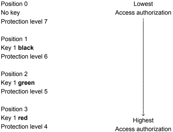
SIEMENS key-operated switch The key-operated switch on the SINUMERIK 840D has 4 settings, assigned to protection levels 4 to 7.
The key-operated switch has three different colored keys which can be removed in the specified positions:
Switch positions
 Position 0
No key
Protection level 7
Lowest Access authorization
 Position 1
Key 1 black
Protection level 6
 Position 2
Key 1 green
Protection level 5
 Position 3
Key 1 red
Protection level 4
Highest Access authorization
Changing access rights The screen is not automatically updated after a change in access authorization (e.g., when the key-operated switch position is changed), but only when the screen is next refreshed (e.g., on closing and opening a directory). The currently valid access authorization is checked every time a function is executed.
If the PLC is in the STOP state, the input image of the machine control panel is not scanned. For this reason, the key-operated switch positions are not evaluated during commissioning.
2-36 ©Siemens AG 2008 All rights reserved.
2 01/2008 Operator Components/Operating Sequences 2.2 Machine control panel (MCP) 2
Passwords As an additional option for setting access authorization, it is possible to enter three passwords in the "Commissioning" operating area. If the password is set, the key-operated switch positions are irrelevant.
References /IAD/, Commissioning Manual 840D.
2.2.6 Program control
 NC Start
If you press the "NC Start" key, the selected part program (part program name is displayed in header) is started at the current block and the associated LED lights up.
 NC stop
If you press the "NC Stop" key, processing of the active part program is halted and the associated LED lights up.
After this, you can continue processing with NC Start.
 Single block
This function allows you to execute a part program block by block. You can activate the "Single Block" function in "Automatic" and "MDA" modes. If single block is activated, the associated LED on the machine control panel lights up.
- If single block execution is active, Stop is displayed on the screen in the cycle (in the program control line)
- The message "Stop: Block completed in single block" is displayed in the channel operational message line (in interrupt state).
- The current block in the part program will not be executed until you press the "NC Start" key.
- Program processing is stopped after one block is executed. You can execute the next block by pressing the "NC Start" key again.
You can deselect the function by pressing the "Single block" key again.

2 Operator Components/Operating Sequences 01/2008 2
2.2 Machine control panel (MCP)
This function is dependent on the settings under "Program control" in the Machine operating area.

Reset
When you press the <Reset> key:
- Execution of the current part program is aborted.
- Messages issued by the monitoring function are deleted (except the alarms POWER ON, NC Start and "Acknowledge alarm").
- The channel is set to "Reset" state, i.e.,
- ~The NC control remains synchronized with the machine.
- ~The control is in its initial state and ready for a new program run.
References /FB/ K1, Description of Functions BAG, Channel, Program control.
©Siemens AG 2008 All rights reserved.
2-38 SINUMERIK 840Di sl/840D sl/840D Operating Manual HMI-Advanced (BAD) - 01/2008 Edition
2.3 SINUMERIK HT 8
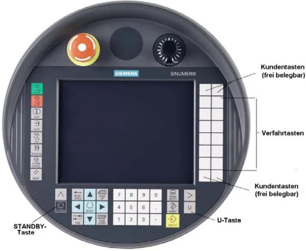
The mobile SINUMERIK HT 8 handheld terminal combines the functions of an operating panel and a machine control panel. It is therefore ideal for visualization, operation, teach-in, and programming at the machine:
- Manipulators/robots
- Machine tools
- Production machines
The 7.5 TFT color display provides touch operation. It also has membrane key for traversing the axes, for numeric input, for cursor control, and for machine control panel functions like start and stop.
Prerequisite
To operate the HT 8, you must have the operator privilege.
Keyboard operation
See section "Machine control panel" for a description of the individual keys.
Machine manufacturer
The four customer keys are freely assignable and can be set up customer-specifically by the machine manufacturer.
This <STANDBY> key presently has no function.
2 Operator Components/Operating Sequences
2.3 SINUMERIK HT 8
Key <U>
The CPF softkey bar is displayed with the <U> key:
CPF softkeys (Control Panel Function)
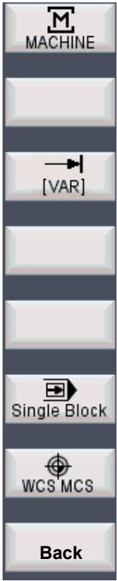
The CPF softkeys keys of the machine control panel emulated by the HMI software. When the HT 8 has operator rights, the CPF menu is displays with the <U> key. The menu is automatically hidden when the area is changed.
The following softkeys are available (see figure on the left):
- <MACHINE> softkey: Select the "Machine" operating area (corresponds to <Shift> + <F10>).
- < [VAR] > softkey: Select the axis feedrate in the increment.
- <Single Block> softkey: Switch single block execution on/off.
- <WCS MCS> softkey: Switching between MCS ↔ WCS
- "Back" softkey: Hide CPF menu; restoration of the user response line and the softkeys.
The CPF menu is not displayed when the area menu or the channel menu is active.
With the <MACHINE> softkey, the "multi-channel display" function is also operator-controllable on the HT 8. The respective state is displayed in the global machine status display (header). (Mail Detlev Lutter from 15.06.2007)
The PLC interface signals, that are initiated using the softkeys of the CPF menus, are edge-controlled.
Traversing keys
JOG and MDA / Teach In mode must be selected to set up the axes with the traversing keys.
The labeling of the 12 traversing keys is shown on the housing of the touch panel. Display of the labeling for up to 6 axes is performed by the PLC program (machine manufacturer).
If the labeling for the traversing keys is displayed, all the other softkeys cannot be operated.
Switch over channel
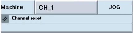
Channel switchover is performed by touch operation of the touch surface on the global machine status display:
©Siemens AG 2008 All rights reserved.

2
Operator Components/Operating Sequences 2.3 SINUMERIK HT 8 2
Virtual keyboard
The virtual keyboard is displayed from the active operator area. The keyboard is automatically hidden again when changing the area or when exiting the application. The virtual keyboard is located across the complete header and can be shifted using the mouse.
Language changeover
The following languages can be selected for the virtual keyboard online: German, English, French, Spanish.
 The virtual keyboard can be displayed and hidden in all operator areas using a touch field located above the vertical softkeys. This touch field is only displayed if the connected HT 8 or Touch Panel has operator rights.
Calibrating touch panel
To perform calibration, press the keys <Recall> + <MENU SELECT> simultaneously to start the command shell:
- The "Calibrate TouchPanel" button starts calibration.
- Follow the instructions on the screen and touch the three calibration points one after the other.
This completes the calibration.
- Then press the horizontal softkey or button "1" to make the connection to the required PCU and return to the HMI-Advanced user interface.
References
"Operator Components and Networking" Manual