5 01/2008 Parameters operating area 5.1 Tool data 5
Assigning the tool-specific parameters
\begin{tabular}{|l|l|l|} \hline Parameters & Significance & Data Type \ \hline Tool-specific parameters & & \ \hline $TC_TPG1 & Spindle number & Integer \ \hline $TC_TPG2 & Chaining rule & Integer \ \hline $TC_TPG3 & Minimum wheel radius & Real \ \hline $TC_TPG4 & Minimum wheel width & Real \ \hline $TC_TPG5 & Current wheel width & Real \ \hline $TC_TPG6 & Maximum speed & Real \ \hline $TC_TPG7 & Maximum peripheral speed & Real \ \hline $TC_TPG8 & Angle of the inclined wheel & Real \ \hline $TC_TPG9 & Parameter number for radius calculation & Integer \ \hline Additional parameters & & \ \hline $TC_TPC1 & Angle of the inclined wheel & Real \ \hline to & & \ \hline $TC_TPC10 & & Real \ \hline \end{tabular}
- Group type 5xx (turning tools):
- 500 Roughing tool
- 510 Finishing tool
- 520 Plunge cutter
- 530 Parting tool
- 540 Threading tool
- 550 Steel profile
- 560 Rotary drill (ECOCUT)
- 580 Oriented probe
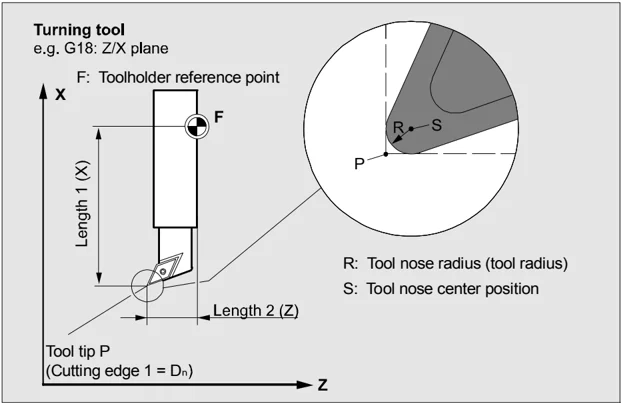
Required offset values for a turning tool with tool radius compensation
©Siemens AG 2008 All rights reserved.
5 Parameters operating area 01/2008 5.1 Tool data 5
Required offset values for a turning tool with tool radius compensation
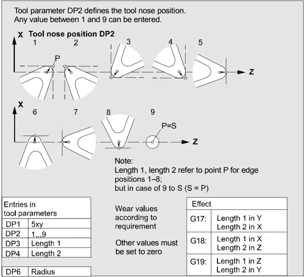
Tool parameter DP2 defines the tool nose position. Any value between 1 and 9 can be entered.
X Tool nose position DP2 1 2 3 4 5 6 7 8 9 P=S
Note: Length 1, length 2 refer to point P for edge positions 1–8; but in case of 9 to S (S = P)
\begin{tabular}{|l|l|l|l|} \hline Entries in & Wear values & Effect & \ tool parameters & according to & G17: & Length 1 in Y \ DP1 & 5xy & requirement & Length 2 in X \ DP2 & 1...9 & Other values must & G18: Length 1 in X \ DP3 & Length 1 & be set to zero & Length 2 in Z \ DP4 & Length 2 & & G19: Length 1 in Z \ & & & Length 2 in Y \ DP6 & Radius & & \ \hline \end{tabular}
- Group type 7xx (special tools):
- 700 Slotting saw
- 710 3D probe
- 711 Edge probe
- 730 Stop
5-166 ©Siemens AG 2008 All rights reserved.

Parameters operating area 5.1 Tool data
Required offset values for slotting saw
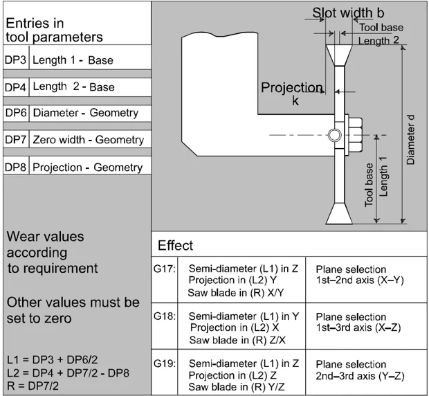
- Type 700 (slotting saw)

The offset data (TOA data) you can enter for tool type 700 "slotting saw" are as follows:
| Geometry | Wear | Base | ||
|---|---|---|---|---|
| Length compensation | ||||
| Length 1 | $TC_DP3 | $TC_DP12 | $TC_DP21 | mm |
| Length 2 | $TC_DP4 | $TC_DP13 | $TC_DP22 | mm |
| Length 3 | $TC_DP5 | $TC_DP14 | $TC_DP23 | mm |
| Radius compensation | ||||
| Diameter | $TC_DP6 | $TC_DP15 | mm | |
| Slot width b | $TC_DP7 | $TC_DP16 | mm | |
| Projection k | $TC_DP8 | $TC_DP17 | mm |
3D probe
Type 710 See /BNM/, User Manual, Measuring cycles
Stop
Type 730 The stop is used to position the material in turning machines with bar feed. Only tool length compensation is important.
©Siemens AG 2008 All rights reserved.
5 Parameters operating area 01/2008
5.1 Tool data
Calculation of tool parameters
Types 1xx (milling cutters), 2xx (drills) and 5xx (turning tools) are calculated according to the same scheme.
Several entries exist for the geometric variables (e.g., length 1 or radius). These are added together to produce a value (e.g., total length 1, total radius), which is then used for the calculations.

5.1 Tool data
Tool base dimension/ adapter
| 21 | Length 1 | |
|---|---|---|
| 22 | Length 2 | |
| 23 | Length 3 |
Technology
| 24 | Clearance angle | For turning tools |
|---|---|---|
| 25 | Clearance angle |
Offsets that are not required must be assigned the value 0 (= default when the offset memory is set up).
The individual values of the offset memory (P1 to P25) can be read and written by the program via system variables.
The tool offsets can be entered not only via the operator panel front but also via the data input interface.
Calculation of tool base dimensions for two-dimensional millhead

| Entries in tool parameters | |
|---|---|
| DP1 | 5xy |
| DP3 | Length 1 - Geometry |
| DP6 | Radius - Geometry |
| DP21 | Length 1 - Base |
| DP22 | Length 2 - Base |
| DP23 | Length 3 - Base |
Wear values according to requirement
Other values must be set to zero
Effect
| G17: | Length 1 in ZLength 2 in YLength 3 in XRadius in Y/Z | |
|---|---|---|
| G18: | Length1 in YLength 2 in XLength 3 in ZRadius in X/Y | |
| G19: | Length 1 in XLength 2 in ZLength 3 in YRadius in Z/X |
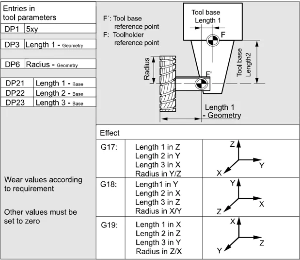
5 Parameters operating area 01/2008 5
5.1 Tool data
Calculation of tool base dimensions for three-dimensional millhead:
\begin{tabular}{|p{0.22\textwidth}|p{0.18\textwidth}|p{0.18\textwidth}|p{0.18\textwidth}|} \hline Entries in tool parameters & \multicolumn{3}{l|}{} \ \hline DP1 5xy & \multicolumn{3}{l|}{} \ \hline DP3 Length 1- Geometry & \multicolumn{3}{l|}{} \ \hline DP6 Radius - Geometry & \multicolumn{3}{l|}{} \ \hline DP21 Length 1 - base & \multicolumn{3}{l|}{} \ \hline DP22 Length 2 - base & \multicolumn{3}{l|}{} \ \hline DP23 Length 3 - base & \multicolumn{3}{l|}{} \ \hline Wear values according to requirement & \multicolumn{3}{l|}{} \ \hline Other values must be set to zero & \multicolumn{3}{l|}{} \ \hline \end{tabular}
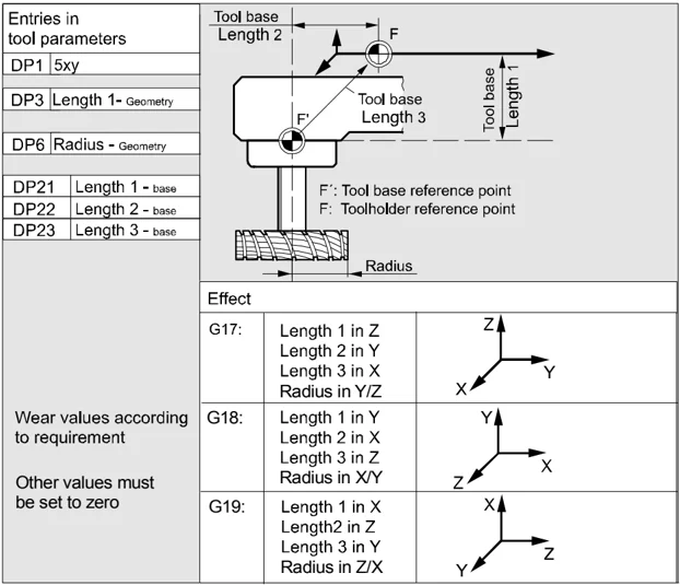
F': Tool base reference point F: Toolholder reference point
Effect G17: Length 1 in Z Length 2 in Y Length 3 in X Radius in Y/Z
G18: Length 1 in Y Length 2 in X Length 3 in Z Radius in X/Y
G19: Length 1 in X Length2 in Z Length 3 in Y Radius in Z/X
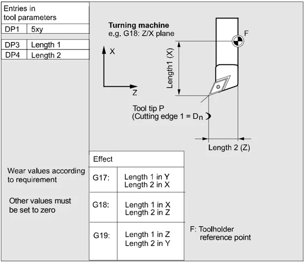
Required length compensation values for turning tools:
\begin{tabular}{|p{0.22\textwidth}|p{0.18\textwidth}|p{0.18\textwidth}|p{0.18\textwidth}|} \hline Entries in tool parameters & \multicolumn{3}{l|}{} \ \hline DP1 5xy & \multicolumn{3}{l|}{} \ \hline DP3 Length 1 & \multicolumn{3}{l|}{} \ \hline DP4 Length 2 & \multicolumn{3}{l|}{} \ \hline Wear values according to requirement & \multicolumn{3}{l|}{} \ \hline Other values must be set to zero & \multicolumn{3}{l|}{} \ \hline \end{tabular}
Turning machine e.g. G18: Z/X plane
Tool tip P (Cutting edge 1 = Dn )
F: Toolholder reference point
Effect G17: Length 1 in Y Length 2 in X
G18: Length 1 in X Length 2 in Z
G19: Length 1 in Z Length 2 in Y
©Siemens AG 2008 All rights reserved.

5
Parameters operating area 5.1 Tool data
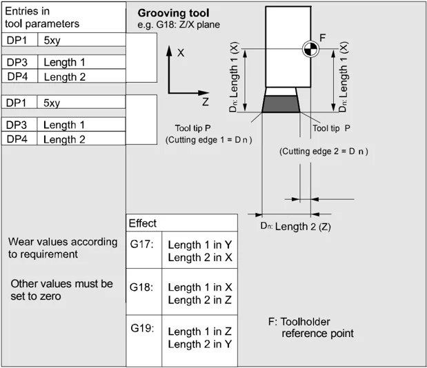
Turning tool with several cutting edges - length compensation:
\begin{tabular}{|p{0.25\textwidth}|p{0.15\textwidth}|p{0.15\textwidth}|p{0.35\textwidth}|} \hline Entries in tool parameters & \multicolumn{3}{l|}{\textbf{Grooving tool}} \ \cline{2-4} & \multicolumn{3}{l|}{e.g. G18: Z/X plane} \ \hline DP1 & 5xy & & \ \hline DP3 & Length 1 & & \ \hline DP4 & Length 2 & & \ \hline DP1 & 5xy & & \ \hline DP3 & Length 1 & & \ \hline DP4 & Length 2 & & \ \hline Wear values according to requirement & Effect & & \ \hline Other values must be set to zero & G17: & Length 1 in Y Length 2 in X & \ \hline & G18: & Length 1 in X Length 2 in Z & \ \hline & G19: & Length 1 in Z Length 2 in Y & \ \hline \end{tabular}

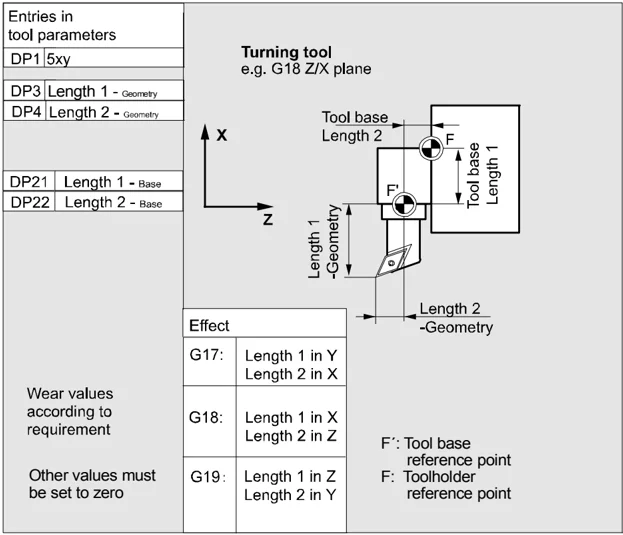
Calculation of tool base dimensions for turning machine:
\begin{tabular}{|p{0.25\textwidth}|p{0.15\textwidth}|p{0.15\textwidth}|p{0.35\textwidth}|} \hline Entries in tool parameters & \multicolumn{3}{l|}{\textbf{Turning tool}} \ \cline{2-4} & \multicolumn{3}{l|}{e.g. G18 Z/X plane} \ \hline DP1 & 5xy & & \ \hline DP3 & Length 1 - Geometry & & \ \hline DP4 & Length 2 - Geometry & & \ \hline DP21 & Length 1 - Base & & \ \hline DP22 & Length 2 - Base & & \ \hline Wear values according to requirement & Effect & & \ \hline Other values must be set to zero & G17: & Length 1 in Y Length 2 in X & \ \hline & G18: & Length 1 in X Length 2 in Z & \ \hline & G19: & Length 1 in Z Length 2 in Y & \ \hline \end{tabular}
©Siemens AG 2008 All rights reserved.
Parameters operating area
5.1 Tool data
Tool type 4xx (grinding tools) is calculated separately.
Several entries exist for the geometric variables (e.g., length or radius).
| Parameters | Grinding wheel-comp. left | Grinding wheel-comp. right | Dresser left | Dresser right |
|---|---|---|---|---|
| Tool-specific parameters | ||||
| $TC_DP1 | Tool type | *(2⁰=1) | Tool type | Tool type |
| $TC_DP2 | Length of cutting edge | Length of cutting edge | Length of cutting edge | Length of cutting edge |
| Geometry tool length compensation | ||||
| $TC_DP3 | Length 1 | *(2²=4) | Length 1 | Length 1 |
| $TC_DP4 | Length 2 | *(2³=8) | Length 2 | Length 2 |
| $TC_DP5 | Length 3 | *(2⁴=16) | Length 3 | Length 3 |
| $TC_DP6 | Radius | Radius | Radius | Radius |
| $TC_DP7 to $TC_DP11 | Reserved | Reserved | Reserved | Reserved |
| Wear tool length compensation | ||||
| $TC_DP12 | Length 1 | *(2¹¹=2048) | Length 1 | Length 1 |
| $TC_DP13 | Length 2 | *(2¹²=4096) | Length 2 | Length 2 |
| $TC_DP14 | Length 3 | *(2¹³=8192) | Length 3 | Length 3 |
| $TC_DP15 | Radius | Radius | Radius | Radius |
| $TC_DP16 to $TC_DP20 | Reserved | Reserved | Reserved | Reserved |
| Base dimension/adapter dimension tool length compensation | ||||
| $TC_DP21 | Basic length 1 | *(2²⁰=1048576) | Basic length 1 | Basic length 1 |
| $TC_DP22 | Basic length 2 | *(2²¹=2097152) | Basic length 2 | Basic length 2 |
| $TC_DP23 | Basic length 3 | *(2²²=4194304) | Basic length 3 | Basic length 3 |
Parameters operating area 5.1 Tool data
| Technology | ||||
|---|---|---|---|---|
| $TC_DP24 | Reserved | Reserved | Reserved | Reserved |
| $TC_DP25 | Reserved | Reserved | Reserved | Reserved |
| Additional parameters | ||||
| $TC_DPC1 | ||||
| to | ||||
| $TC_DPC10 |
- Value of the chaining parameter if the compensation parameters is to be chained.
With this parameter it is possible to define which offset value is used for grinding wheel peripheral speed, tool monitoring and centerless grinding. The value always refers to cutting edge D1.
| $TC_TPG9 = 3 | Length 1 (geometry + wear + base, depending on tool type) |
|---|---|
| $TC_TPG9 = 4 | Length 2 (geometry + wear + base, depending on tool type) |
| $TC_TPG9 = 5 | Length 3 (geometry + wear + base, depending on tool type) |
| $TC_TPG9 = 6 | Radius |
*: The tool parameter of cutting edge 2 is chained to the parameter of cutting edge 1 (see tool-specific grinding data $TC_TPG2, chain rule). Here, typical chains are shown and the associated place value is specified in brackets.
This parameter contains the number of the spindle to which the monitoring data and GWPS refer.
This parameter defines which tool parameters of the right wheel edge (D2) and left wheel edge (D1) must be chained (see TOA data). If the value of one of the chained parameters is changed, it is then automatically included in the chained parameter.
It must be noted that the minimum grinding wheel radius must be specified in the Cartesian coordinate system for an inclined grinding wheel. The length compensations always specify the distances between the toolholder reference point and the tool tip in Cartesian coordinates.
The monitoring data apply to both the left-hand and the right-hand cutting edge of the grinding wheel. The tool lengths are not automatically compensated when the angle is altered. On inclined axis machines the same angle must be specified for the inclined axis and the inclined wheel.
©Siemens AG 2008 All rights reserved.

5 Parameters operating area 01/2008 5 5.2 Tool offset
Offsets that are not required must be assigned the value 0 (= default when the offset memory is set up). The tool offsets can be entered not only via the operator panel front but also via the data input interface.
For programming offset data, see /PG/, Programming Guide Fundamentals
5.2 Tool offset
5.2.1 Function and main screen Tool offset
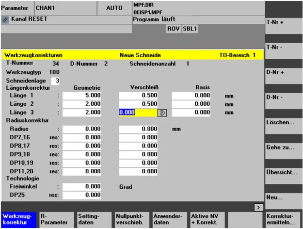
Tool offset data consist of data which describe the geometry, wear, identification, tool type and the assignment to parameter numbers. The unit used for the dimensions of the tool is displayed. The input field is highlighted.

Every offset number contains up to 25 parameters, depending on the tool type. The number of parameters shown in the window is that for the tool type.
The maximum number of offset parameters (T and D numbers) can be set by means of machine data.
5-174 ©Siemens AG 2008 All rights reserved.

5 01/2008 Parameters operating area 5.2 Tool offset 5
Tool wear: Fine offset If you at least have the right entered in MD 9202: USER_CLASS_TOA_WEAR, you can incrementally change the values of the tool fine offset. The difference between the old and new values must not exceed the limit stored in MD 9450: WRITE_TOA_FINE_LIMIT.
Horizontal softkeys
You can select different data types with the horizontal softkeys:
\begin{tabular}{ll} Tool offset & Selection of "Tool offset" menu \ R-Parameter & Selection of "R parameters" menu \ Setting data & Selection of "Setting data" menu \ Work offset & Selection of "Work offset" menu \ User data & Selection of "User data" menu \ Determine offset & Support in determining tool offsets. This softkey is not required if the tool management function is available. \ T-No. + & Selection of the next tool \ T-No. - & Selection of the previous tool \ D-No. + & Selection of next highest offset number (cutting edge) \ D-No. - & Selection of next lowest offset number (cutting edge) \ Delete... & Deletion of a tool or cutting edge \ Go to... & Find any tool or the active tool \ Overview & List of all available tools \ New & New cutting edge or a new tool \ \end{tabular}
Vertical softkeys
The vertical softkeys support data input:
©Siemens AG 2008 All rights reserved.

5 Parameters operating area 01/2008
5.2 Tool offset
5.2.2 New tool

Function
If you create a new tool, the relevant tool types are automatically pre-selected as input support when you select the tool group.
Sequence of operations
The "Tool offset" window is displayed automatically.
Press the "New tool" softkey. The "Create new tool" window appears on the screen. Once you have entered the initial digits for the tool group, all the available tool types within the 5xx group will be displayed for you so that you can select one: e.g., "5xx turning tools"
- 500 Roughing tool
- 510 Finishing tool
- 520 Plunge cutter
- 530 Parting tool
- 540 Threading tool
- 550 Steel profile
- 560 Rotary drill (ECOCUT)
- 580 oriented probe
Enter the digits for your selections via the alphanumeric keypad or select them from the displayed list.
No new tool is created.
A new tool is created. The window is closed.
Creates another tool. The window remains open so that you can create other new tools.
Creates another cutting edge for the tool you have just created. The window remains open.
Tool offset
New...
New tool
Abort
OK
OK + new tool
OK + new cutting
©Siemens AG 2008 All rights reserved.

5
Parameters operating area 5.2 Tool offset
5.2.3 Display tool
Function
You can select tools that you have created and access their tool offset data.
Tool offset
Sequence of operations
The "Tool offset" window is displayed automatically.
If the "Parameters" area has already been selected, the window and the last tool selected when the area was exited are displayed. The tool offset data of the current tool are displayed immediately. If no tool has yet been selected, the data of the first tool are shown together with its first D number.
If no tools are available in the area, a message is output.
T-No. +
T-No.
Select the created tools.
Additional information
Input of the geometry and wear data of the tool can be disabled using the keylock switch.
©Siemens AG 2008 All rights reserved.

5 Parameters operating area 01/2008
5.2 Tool offset
5.2.4 Deleting a tool
Function
The tool is deleted together with all its cutting edges and the tool list updated accordingly.
Sequence of operations
The "Tool offset data" window is displayed automatically.
Scroll the screen contents until you reach the tool to be deleted.
The vertical softkey bar changes when the "Delete" softkey is selected.
Press the "Delete tool" softkey. The tool and all its edges are deleted. The tool offsets of the tool number preceding the deleted tool are displayed.
©Siemens AG 2008 All rights reserved.
5.2.5 New cutting edge
Function
To help you to select a new cutting edge, the associated tool types are displayed automatically when you select a tool group.
Sequence of operations
The "Tool offset" window is displayed automatically.
Press the "New ..." and "New cutting edge" softkeys. The "New cutting edge" window is displayed. Once you have entered the initial digits for the tool group, all the available tool types within the 5xx group will be displayed for you so that you can select one: e.g., "5xx turning tools"
- 500 Roughing tool
- 510 Finishing tool
- 520 Plunge cutter
- 530 Parting tool
- 540 Threading tool
- 550 Steel profile
- 560 Rotary drill (ECOCUT)
- 580 oriented probe
The possible cutting edge positions are displayed automatically for some tool types (e.g., for special tools, turning tools, grinding tools). Enter the appropriate digit on the alphanumeric keyboard. Creation of a new cutting edge is aborted.
A new cutting edge is created.
A new cutting edge is created. Another new cutting edge can be created.
A new cutting edge is created. Another new tool can be created.

5 Parameters operating area 01/2008 5
5.2 Tool offset
5.2.6 Deleting a cutting edge
! Delete Delete edge
Function
You can delete one or several edges of a tool. The tool list is updated automatically.
Select the cutting edge of a tool, press the "Delete" softkey and then the "Delete edge" softkey.
5.2.7 Determining a tool offset
!
Function
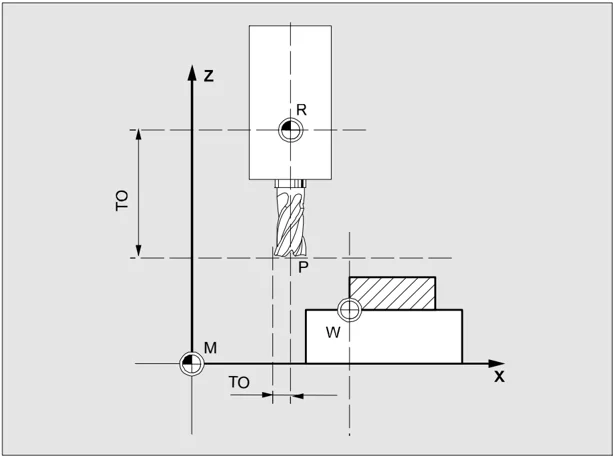
The "Determine tool offset" function allows you to change the absolute coordinates of different axes and then to calculate them.

TO Tool offset, absolute coordinate R Tool adapter point M Machine zero W Workpiece zero
The tool offset is only calculated in the machine coordinate system (MCS).
5-180 ©Siemens AG 2008 All rights reserved.
5
Parameters operating area 5.2 Tool offset
Sequence of operations
The "Tool offset" window is displayed.
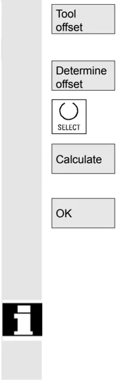
Position the cursor on the tool parameter you wish to change. The "Absolute coordinate" window opens.
Select the appropriate axis with the "Toggle key". Alter the reference value, if necessary, using the numeric keypad.
Position – reference value is entered in the input field. The window remains open.
When you press the "OK" softkey, the current position and corresponding reference value for the selected tool parameter are calculated.
The following applies: Position – reference value = input value The window is closed.
If "Jog" mode is selected, it is also possible to change the position by traversing the axes. The control automatically calculates the value from the reference value and the new position.
5.2.8 Make tool offset immediately effective
Function
The machine data can be set to specify that the active tool offset can be activated immediately if the part program switches to the "Reset" or "Stop" state.
Additional information
When the function is used in the Reset state, the machine data item $MC_RESET_MODE_MASK must be set such that the offset is not reset when the program switches to Reset.
References
Function Manual Basic Functions (FB1): Axes, coordinate systems, frames (K2); Chapter "Additive offsets"
Caution
The offset is applied after NC Start of the Reset in response to the next programmed axis movement in the part program.
©Siemens AG 2008 All rights reserved.

5 Parameters operating area 01/2008 5
5.3 Tool management
The tool management system is organized by means of various configurable lists which show different views of the tools used.
Magazine list In the "Magazine list", the tools of a magazine are displayed in order of ascending magazine location numbers.
You can search for, display and, in the majority of cases, edit the data. A function is also provided for checking the D numbers and subsequently activating tools.
This list is mainly used to load and unload tools during setup, and to move tools between magazines.
Tool list In the "Tool list", the tools are displayed in the order of ascending T numbers.
You use this list if you are working with small tool magazines and know the exact magazine location of each tool.
Working offset list The cutting edges of active replacement tools are displayed in the "Working offset list". They are sorted in order of ascending D numbers.
You can search (according to D number/DL number), display and edit the data.
Notice Use this list to edit and monitor sum offsets (local offsets), quantities and cutting edge parameters during the machining process. You can configure up to three different views for the working offset list. The TOA is assigned to multiple channels and is effective in the channel in which the tool is active. If you want to change the wear in the list of working offsets without having to call the tool again at the next NC Start, ensure that the correct channel is selected for this tool.
5 01/2008 Parameters operating area 5.3 Tool management 5
Tool catalog and tool cabinet
The tool catalog contains only "ideal" tools. "Ideal" tools are characterized by the relevant tool "master data" (i.e., with ideal tool dimensions, no wear, etc.). An "ideal" tool is uniquely defined by its "tool name".
The tool cabinet contains "real" tools only. "Real" tools (i.e., real tool dimensions, with wear, etc.) are characterized by the relevant tool "offset data". A "real" tool is uniquely defined by its "tool name" and the associated "Duplo number". It is the "Duplo number" that assigns actual data to a "real" tool.
If a connection to a host computer exists, a message is automatically output to this host computer when a tool is loaded (but not relocated), unloaded or deleted, and the corresponding data block is transferred. The data are then still available on the host computer even after the tool has been deleted.
Machine manufacturer
Please refer to the information supplied by your machine manufacturer to see which functions are included in your tool management. See /FBW/ Description of Functions, Tool Management or /FBSP Description of Functions, ShopMill
5.3.1 Main tool management functions
The tool management system offers various tool types for selection. You can assign geometric and technological data to the tool types in order to set up your master tool data. Several versions of each tool can exist. You can assign the current data of the tool used (particular tool data) to these versions.
You start the tool management function from the "Parameters" operating area by pressing the relevant softkey.
The machine manufacturer configures which list is to be displayed when the tool management system is called up. In the example shown, the current "Magazine list" is displayed.

5 Parameters operating area 01/2008 5
5.3 Tool management
I Important!
The structure of the table is freely configurable (configured by the machine manufacturer). The example shows only one possible case:
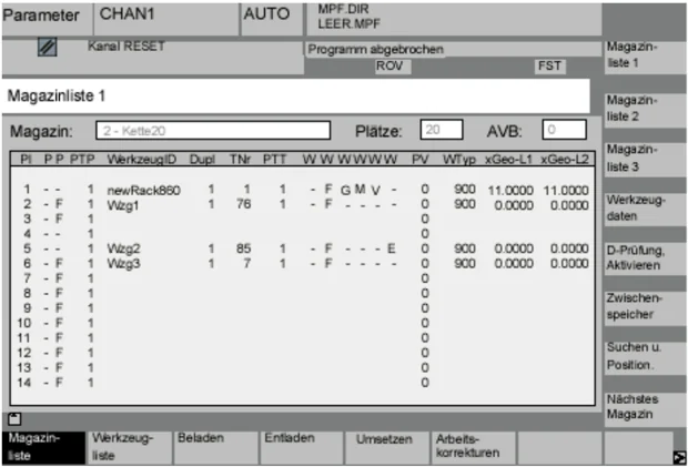
Location (PI) Location number
Location state (P) Location state (one column is provided for each state) For example F = Location enabled G = Location disabled Z = Reserved for tool in buffer B = Reserved for tool to be loaded L = Left half location occupied R = Right half location occupied O = Upper half location occupied U = Lower half location occupied I = Left half location reserved r = Right half location reserved o = Upper half location reserved u = Lower half location reserved
PTP Type assigned to the location
Tool ID Name of the tool
5
Parameters operating area 5.3 Tool management
5
\begin{tabular}{ll} \textbf{Dupl} & Number of replacement tool \ \textbf{TNo} & Internal T numbers, which may be needed for reloading tool data. \ \textbf{PTT} & Type of location assigned to the tool \ \textbf{W (8x)} & Tool status \ & (one column is provided for each status) \ & No display = Replacement tool \ & A = Active tool \ & F = Tool enabled \ & G = Tool disabled \ & M = Tool is measured \ & V = Warning limit is reached \ & W = Tool is being changed \ & P = Tool is fixed-location-coded \ & E = Tool has been in use \ & R = Unloading marking ("radius") \ & B = Loading marking \ & S = Master tool \ \textbf{PV} & Wear group assigned to the tool. \ \textbf{WTy} & Tool type \ & Only some of the tool offsets are enabled for input, depending on the \ & tool type. \ & All other tool types are preset to a value of 0. \ \textbf{Geo – Len 1} & Tool offsets such as length, radius, wear, monitoring data, etc. \ \textbf{Radius ...} & \ \end{tabular}
Horizontal softkeys
Magazine list The first or most recently displayed magazine is shown in the "Magazine list" together with all the tools which have been loaded. You can access the next magazine by pressing the corresponding vertical softkey.
Tool list All tools which are stored as a set of data on the NC are displayed (irrespective of whether they have been assigned to a magazine location).
Load A magazine location is assigned to the tool.
5 Parameters operating area 01/2008
5.3 Tool management
Unload The tool is deleted from the current magazine location.
Relocate The tool is moved from the current magazine location to another location.
Working offset The cutting edges of active replacement tools are displayed. They are sorted in order of ascending D numbers.
Further softkeys are displayed when you press the "ETC." key:
Tool catalog You can create new tool master data ("ideal" tools) and edit the existing data.
Tool cabinet You can create new tool offset data and tool operating data ("real" tools) and edit the existing data.
Transformation This softkey allows you to display the tool data as transformed data (adapter data are calculated) or non-transformed data.
This conversion feature is only available in the magazine list display. The data are always displayed as non-transformed data in the tool list and as transformed data in the working offset list.
Special feature: If you display transformed data and want to create a new tool in the magazine list (loading mode), the transformed data display is activated exclusively for input of this data block.
Vertical softkeys (magazine list)
(Names assigned by user) Selection of user-specific display windows (if configured), e.g.,,
- General data
- Geometry data
- Wear data
Magazine list 1
Magazine list 2
Magazine list 3
5
Parameters operating area 5.3 Tool management
5
\begin{tabular}{p{0.18\textwidth} p{0.78\textwidth}} Tool data & You can display and edit the complete data of a tool. \ & Call up the start screen for updating the tool data. You can display and normally also edit all the data of the tool, its cutting edges and its working offsets in this screen and subsidiary screens. The vertical softkey bar changes. \ & The exact procedure is described under "Display/edit tool data" (see Page "Display/edit tool data"). \ Activate D check & \textbf{Two functions are implemented with this softkey:} \ & \textbullet{} Verify unique D number assignment \ & \quad Duplication can occur when assigning D numbers to the cutting edges of the individual tools. This function checks all numbers within the current magazine or all allocated D numbers within a TO unit (configured by parameter). \ & \textbullet{} Activate the tools \ & \quad If unique D numbers were assigned, a wear group is activated. A tool is subsequently activated from each replacement tool group in the TOA of the current channel. Allowance is made for the active wear group. \ i & Only automatically accessible magazines are considered for processing. Any previously active tools are disabled by the activation of tools, especially if the wear group is changed. \ Buffer & Display and hide the buffer window in the magazine list. The display shows spindles, grippers, etc., i.e., locations which can accommodate tools but which are not magazine locations. If no buffer is defined, this key has no function. \ \end{tabular}


5 Parameters operating area
5.3 Tool management
The "Find tool/location" window appears.
Search & position.
- Search
- Tool: Enter the tool name and Duplo number and start the search with OK. The cursor is positioned on the tool found.
- Location: Enter the magazine and location number and start the search with OK. The cursor is positioned on the tool found.
- Positioning Select the "Position" softkey, tool/location is moved to loading point. If there is more than one possible loading point, a window is opened. You can select the correct one with the cursor.
Next magazine
The locations of the next magazine are displayed in the magazine list.
You can only scroll forwards. When you reach the last magazine, the display returns to the first magazine.
Vertical softkeys (tool list)
(Names assigned by user)
Selection of a table structure configured by the user (if configured), e.g.:
- General data
- Geometry data
- Wear data
Tool list 1 Tool list 2 Tool list 3 Tool details
You can display and edit the complete data of a tool (as in the magazine list).
Tool from CC Tool in cabinet
The tool data are read from a code carrier and entered in the tool list (you can then edit the data). Select the tool in the tool cabinet. The tool data are read from there and entered in the tool list. A list display appears for which you can parameterize a filter for the tool number, duplo number and tool type. The list displays all the tools that fulfill the filter criteria. You can select the tool you require from the list.

5
Parameters operating area
5.3 Tool management
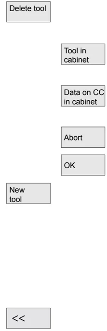
\begin{tabular}{ll} Delete tool & The selected tool is removed from the list. Use the vertical softkeys to determine whether to save the tool data. \ Tool in cabinet & The data are copied into the tool cabinet. The tool can be loaded later with the same data. \ Data on CC in cabinet & If a code carrier is installed, the tool data are stored on the carrier. The tool can then be loaded later with the same data. \ Abort & The operation is canceled. The tool is not removed from the list. \ OK & The tool is deleted from the list. The tool data are no longer available. \ New tool & Each time you press this softkey, a tool is created immediately. The screen form for entering the tool data (tool details) and the associated softkey bar (same as tool details) appear. The values are initialized with the default settings (configured in the INI file) and can be edited here (e.g., you can change the name of the tool). Use the vertical softkey bar to display the tables for cutting edge data and offsets with the default settings. If necessary, enter any changes in the individual views. \ $<<$ & Terminates input of the tool data and switches to the tool list display. The new tool appears in the table and is available for loading. \ & Once you have set up a new tool, the cursor automatically jumps to the line containing the new tool when you return to the tool list. This gives you feedback about your operation. \ \end{tabular}