8 Diagnostics operating area 01/2008 8.4 Service displays
8.4.1 Service axis
Function
The information in the "Service Axis" display is used to
- check the setpoint branch (e.g., position setpoint, speed setpoint, spindle speed setpoint prog.)
- check the actual-value branch (e.g. position actual value, measuring system 1/2, actual speed value), optimize the position control of the axis (e.g. following error, control difference, servo gain factor)
- check the entire control loop of the axis (e.g. through position setpoint/actual-value comparison and speed setpoint/actual-value comparison)
- check hardware faults (e.g. encoder check: If the axis is moved mechanically, the actual position value must change)
- set and check axis monitoring functions.
References: /FB/, Description of Functions D1, Diagnostics Tools
Sequence of operations
Select the menu "Service displays". The softkey bars change. The vertical softkeys are context-sensitive according to the service display. The softkeys in the horizontal menu bar allow you to select the corresponding service displays.
Press the "Service axis" horizontal softkey The "Service axis/spindle" window displays reference values and units for the machine axis together with axis name and axis number.
You can page up and down with the "Page" keys.
Vertical softkeys for axis selection
The service values of the next (+) and the previous (-) axis are displayed.
The "Direct selection" vertical softkey in the window of the same name allows you to select an axis directly from the list of available axes.
8.4.2 Service drive
Function
The information contained in the "Drive service" display is used to
- Check the status of the enable and control signals (e.g., pulse enable, drive enable, motor selection, setpoint parameter set)
- Check the status of the FDD/MSD operating modes (e.g., setup mode, parking axis)
- displaying temperature warnings
- Check the current setpoint/actual-value display (e.g. position actual-value measuring system 1/2, speed setpoint, speed actual value)
- check the drive status
- displaying the current ramp-up phase
- Display the group error message (message status class 1)
- Display the status messages of the drive (e.g. threshold torque not reached, actual speed = set speed)
References
/FB/, Description of Functions D1, Diagnostics Tools
Sequence of operations
Select the menu "Service displays". The softkey bars change. The vertical softkeys are context-sensitive according to the service display. The softkeys in the horizontal menu bar allow you to select the corresponding service displays.
The "Drive service" window displays information about the axis drive together with axis name and number.
You can page up and down with the "Page" keys.
V ertical softkeys for axis selection
The service values of the next (+) and the previous (-) drive are displayed.
The "Direct selection" vertical softkey in the window of the same name allows you to select an axis directly from the list of available axes.
8 Diagnostics operating area 01/2008
8.4 Service displays
8.4.3 Service SI (Safety Integrated)
- is_aid_in_chart_of_chart_of_chart_of_chart_of_chart_of_chart_of_chart_of_chart_of_chart_of_chart_of_chart_of_chart_of_chart_of_chart_of_chart_of_chart_of_chart_of_chart_of_chart_of_chart_of_chart_of_chart_of_chart_of_chart_of_chart_of_chart_of_chart_of_chart_of_chart_of_chart_of_chart_of_chart_of_chart_of_chart_of_chart_of_chart_of_chart_of ........
8 01/2008
Diagnostics operating area
8.4 Service displays
Status SI (default setting)
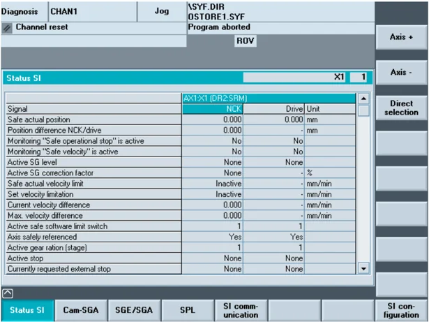
Available signals/values
- Safe actual position
- Position deviation NCK/drive
- "Safe operating stop" monitoring active
- Safely-reduced speed" monitoring active
- Active SG step
- Active SG correction factor
- Safe actual speed limit
- Setpoint speed limit
- Actual speed difference
- Maximum speed difference
- Active safe software limit switch
- Axis safely referenced
- Active gear ratio (step)
- Active stop
- Currently requested external stop
- Pulses enabled
- Axis at standstill (SGA "n < nx" =1)
- Request, “close brake”
- Traversing inhibit due to a stop on another axis
- “Test stop” – selection active
- Stop F code value
8 Diagnostics operating area 8.4 Service displays
"Cam SGA" softkey Using this softkey you can select the display of "cam SGA" signals.
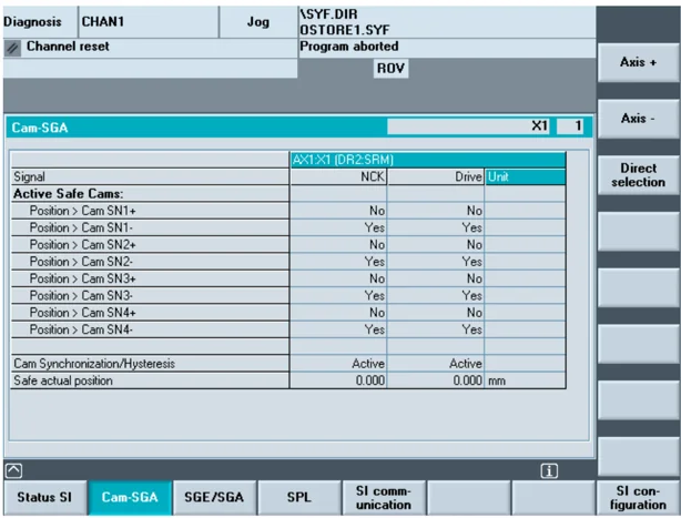
Cam synchronization is executed between NCK and PLC at the cam SGA.
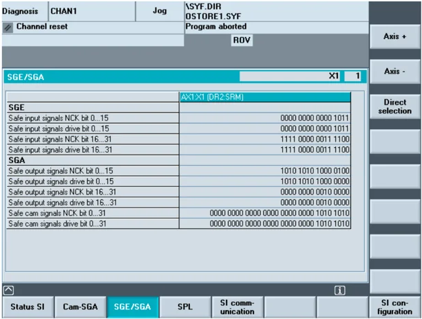
"SGE/SGA" softkey Using this softkey, you can display the signals of the safety-relevant inputs and outputs.
8
Diagnostics operating area 8.4 Service displays 8
"SPL" softkey
Use this softkey to display the safe programmable logic signals SPL.
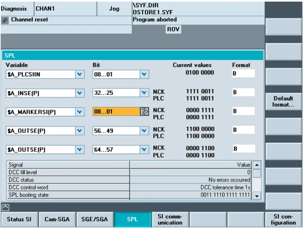
The available signals can be seen in the above screen.
Selectable variables
In the "Variable" selection box, you can choose: $A_INSE(P) corresponds to simultaneously selecting $A_INSE upper line, origin of the NCK and $A_INSEP bottom row; PLC origin
effectively the same for the other variables: $A_OUTSE(P) $A_INSI(P) $A_OUTSI(P) $A_MARKERSI(P) $A_PLCSIIN $A_PLCSIOUT
Saving
The variables that have been selected and the associated bit areas are saved and are taken into account when subsequently selecting the screen.
Bit
Under Bit you can request an 8-bit range from the selected signal. In addition to the current values, the origin of the displayed NCK/PLC signals is displayed.
8 Diagnostics operating area 01/2008 8
8.4 Service displays
Format The following formats can be selected in the variable rows using the "Select" key: B Binary H Hexadecimal D Decimal
The same formats can be selected in the submenu using the "Pre-assigned format..." softkey. The selected format is applied to all variable displays in the screen.
Individually set or fixed format settings are saved and taken into consideration in the following displays.
Signal ... value KDV level (KDV = cross-checking) Cross-checking status Cross-checking control word SPL powered-up state SPL powered up SPL interfaces are parameterized "SAFE.SPL" SPL program file loaded NCK and PLC state Interrupt for SPL start should be assigned Interrupt has been assigned for SPL start Interrupt processing for SPL start called Interrupt processing for SPL start terminated SPL start via Prog_Event NCK cross-checking has been started PLC cross-checking has been started Cyclic SPL checksum test active All SPL protective mechanisms active
8 01/2008 Diagnostics operating area 8.4 Service displays 8
"SI communication" softkey
Function
Using this softkey, you can select the display of the Safety Integrated communication: The dialog box "SI communication (general)" indicates the communication data for sending (F_SENDDP) and receiving (F_RECVDP) in a tabular form.
SI communication (Example: SINUMERIK solution line)
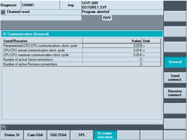
Signals The following signals and values are displayed in this dialog box:
- Parameterized CPU-CPU communication clock cycle status
- Actual CPU-CPU communication clock cycle status
- Maximum CPU-CPU communication clock cycle
- Number of active send data connections (F_SENDDP)
- Number of active receive data connections (F_RECVDP)
"General" softkey Vertical softkeys: Displays the "SI communication (general)" dialog box.
"Send connection" softkey This means that you change to the "SI communication (send)" dialog box.
"Receive connection" softkey This means that you change to the "SI communication (receive)" dialog box.

8 Diagnostics operating area
8.4 Service displays
Function
"Send connection" softkey
The "SI communication (send)" dialog box contains a list of the configuration in tabular form and the status of F_SENDDP.
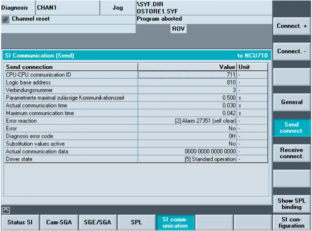
Signals
The following signals of the selected connection (in this case, e.g. NCU710) are displayed in this dialog box:
- CPU-CPU communication ID
- Logical base address
- Connection number
- Parameterized maximum permissible communication time
- Actual communication time
- Maximum communication time
- Error reaction Error reactions that can be set: [0] "Alarm 27350 + STOP D/E" [1] "Alarm 27350" [2] "Alarm 27351 (self-clearing)" [3] "No response from the system"
- Errors
- Diagnostics error code
- Replacement values active
- Actual communication data
8 01/2008 Diagnostics operating area 8.4 Service displays 8
- Driver state Status code: [0] "Not initialized" [1] "Establish communication after booting" [2] "Establish communication after error" [3] "Wait for checkback signals SN=1" [4] "Receiver waits for user acknowledgement" [5] "Normal operation"
Vertical softkeys:
"Connection +" softkey Changes to the next send connection (F_SENDDP). If less than 2 connections are configured, then this softkey is not displayed.
"Connection –" softkey Changes to the previous send connection (F_SENDDP). If less than 2 connections are configured, then this softkey is not displayed.
"General" softkey Displays the "SI communication (general)" dialog box.
"Send connection" softkey This means that you change to the "SI communication (send)" dialog box.
"Receive connection" softkey This means that you change to the "SI communication (receive)" dialog box.
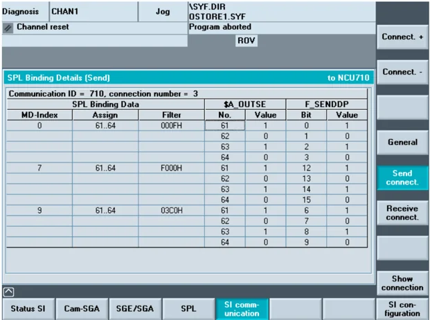
"Display SPL connection" softkey This means that you change to the "Details, SPL connection (send)" dialog box. This softkey can only be selected if send connections have been configured.
"Display connection" softkey This means that you change to the "SI communication (send)" dialog box.

8 Diagnostics operating area
8.4 Service displays
Function
"Display SPL connection" softkey
Additional details are displayed in the "Details, SPL connection (send)" dialog box – e.g. the connection data that has been set and the actual communication data.

Function
"Receive connection" softkey
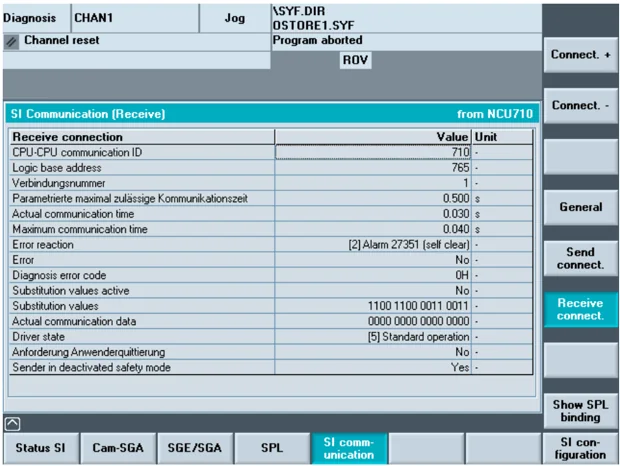
Data for F_RECVDP are displayed using the "Receive connection" softkey.

8.4 Service displays
Signals
The following signals of the selected connection (in this case, e.g. NCU710) are displayed in this dialog box:
- CPU-CPU communication ID
- Logical base address
- Connection number
- Parameterized maximum permissible communication time
- Actual communication time
- Maximum communication time
- Error reaction
Error reactions that can be set:
[0] "Alarm 27350 + STOP D/E"
[1] "Alarm 27350"
[2] "Alarm 27351 (self-clearing)"
[3] "No response from the system"
- Errors
- Diagnostics error code
- Replacement values active
- Actual communication data
- Driver state
Status code:
[0] "Not initialized"
[1] "Establish communication after booting"
[2] "Establish communication after error"
[3] "Wait for SN=1"
[4] "Wait for user acknowledgement"
[5] "Normal operation"
- Request user acknowledgement
- Sender in the deactivated safety mode

8 Diagnostics operating area
8.4 Service displays
Function
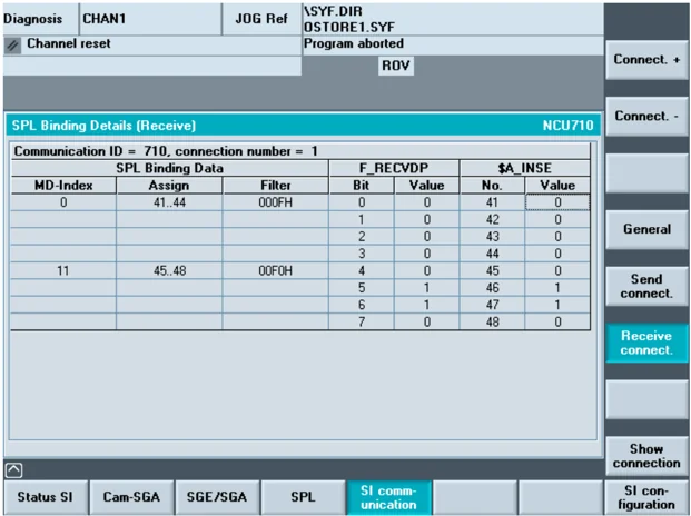
"Display SPL connection" softkey
Additional details are displayed in the "Details, SPL connection (receive)" dialog box – e.g. the connection data that has been set and the actual communication data.
Function
"SI configuration" softkey
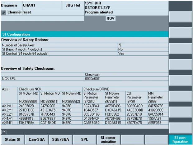
Using this softkey, you select the display of the "SI configuration", i.e. the safety options and the safety checksums of the selected configuration.
SI configuration (Example: solution line)
8
Diagnostics operating area 8.4 Service displays
The "SI configuration" display includes two information areas; these are displayed in a tabular form:
- An overview of the settings of the Safety Integrated option
- Two tables indicate the checksum for the actual Safety Integrated configuration.
The overview of the Safety Integrated Options includes the number of the Safety Integrated axes configured in machine data 19120 $ON_NUM_SAFE_AXES as well as an overview of the active Safety Integrated options in machine data 19122 $ON_NUM_SPL_IO.
Especially the safe options are coded as follows: 0 == No inputs/outputs 1 == SI basic (4 inputs, 4 outputs) 2 == SI comfort (64 inputs, 64 outputs) 4 == High Feature (still not available)
for solution line
The overview of the Safety Integrated checksum area includes the checksum for the SAFE.SPF file as well as a table with the axial SI checksums for NCK, SI motion parameters, CU parameters and motor module parameters for each axis (and the corresponding drive) for which safety integrated was enabled: 36901 $MA_SAFE_FUNCTION_ENABLE <> 0
The checksum data are obtained from the following machine data and drive parameters: MD 36998[0] Equal to MD 36998[1] Equal to MD 36998[2] Equal to SI Motion Parameter [0] r9728[0] SI Motion Parameter [1] r9728[1] CU Parameter r9798 MM Parameter r9898

8 Diagnostics operating area 01/2008 8
8.4 Service displays
8.4.4 Systemressourcen anzeigen
Function
For the NC areas you can display the system resources (utilization display) currently being used: Net and gross runtimes of
- position controller,
- interpolator and
- preprocessing.
Sequence of operations
The "Diagnostics" operating area is selected.
Press the "Service displays" softkey then "System resources". The "NC utilization" screen is displayed.
The following minimum/maximum total data for the servo, IPO cycle and preprocessing are displayed:
- Net runtime in ms
- Gross runtime in ms
- Level of the IPO buffer in percent
- Total capacity utilization in percent
The display update can be halted with the "Stop" softkey, the displayed values are updated again with the "Start" softkey.
Diagnostics Service displays System- resources S top S tart
8
Diagnostics operating area 8.4 Service displays 8
8.4.5 Configuration data output
Function
The configuration data of a machine (HMI version, NCU version, axis configuration, drive configuration, bus parameters, active bus nodes) can be written into a file and subsequently read out or printed.
Configuration data is output in 2 stages:
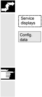
- Creation of the configuration data file CONFIGURATION_DATA in the "Diagnostics" operating area by pressing the "Config. data" softkey.
- Read-out of the CONFIGURATION_DATA file in the "Services" operating area. The configuration file CONFIGURATION_DATA is created in the "Services" operating area for this purpose.
Sequence of operations
Select the menu "Service displays". The horizontal softkey bar changes. Press the "Config. data" softkey. The system gathers the configuration data, writes it into the file CFGDAT.TXT and displays it. The path and name of the file are output in the info line.
Additional information
The configuration data can be read out in the "Services operating area.
8.4.6 Communication error log
Function
Errors that occur during communication between the HMI and NCK/PLC are registered in a communication error log. You can display the errors by pressing this softkey.
The error log file is principally used by the control manufacturer (Siemens) as a diagnostic tool for communication errors.

8 Diagnostics operating area
8.5 Calling theversion screen
8.4.7 Action log
 Action log
A existing action log can be displayed with the corresponding authorization (access level: manufacturer).
For configuration of the action log, see IM4 Commissioning Manual HMI-Advanced
8.5 Calling theversion screen
Function
The version data of the installed system software are output in the Version display:
For SINUMERIK powerline Sort and save functions are available for the displayed version data. Version displays saved as ASCII files can be edited as required or sent to the hotline in the event of an error.
For SINUMERIK solution line The version data displayed under "NCU Version" state the software versions on the CF board: This especially applies to measurement cycles and cycle versions. The measurement cycles and cycles that are used by HMI-Advanced are available on the hard disk of the PCU. Their version can be queried via the horizontal softkeys.
Detail
With the "Detail" softkey, you can query further information about a version, for example, to pass it on to hotline support personnel if service is required.
Checking is performed the first time the version display is accessed.
In the case of SINUMERIK solution line, the version number is 8 digits long and structured as follows:
V xx.yy.zz.nn
xx: Major Release yy: Minor Release zz: Service pack nn: Hotfix Number

8
Diagnostics operating area
8.5 Calling theversion screen
8

Sequence of operations
Service displays
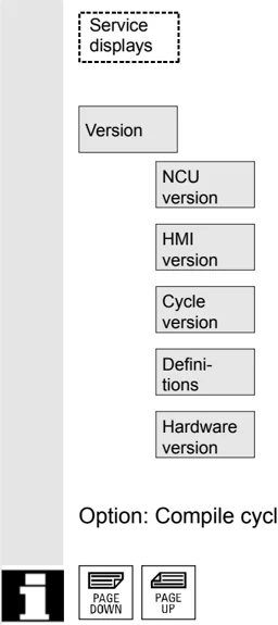
Press the "Service displays" softkey. The horizontal softkey bar changes.
Version
Open the "Version" window with the following softkeys:
NCU version
"NCU version" for the version data of the NCU and
HMI version
"HMI version" for the version data of the HMI.
Cycle version
"Cycle version" Version data for each of the cycle packages
Defini- tions
"Definitions" The version data for definitions
Hardware version
"Hardware version" for the version data of the hardware. (only available for SINUMERIK solution line)
Option: Compile cycles
If "Compile cycles" is available on the NCK, the version is displayed.
PAGE DOWN PAGE UP
Use the "Page" keys to scroll up and down.
8.5.1 Sorting and saving version data

Function
There are various sorting functions for the following version lists:
- NCU version
- HMI version
- Cycle version
- Definitions
Sort
In the left-hand part of the pane for sorting, you can select a sort criterion from the column designations in the list by pressing the Select key. In the right-hand pane you can choose from descending and ascending sorting sequence for the selected sort criterion.
8 Diagnostics operating area 01/2008 8
8.5 Calling theversion screen
Save versions The sorted and unsorted version displays of the display area are saved as follows for HMI versions:
Range Target File HMI version Services→Diagnostics\Log files HMI.COM
Specific features of HMI versions How to save the other areas is described in the area descriptions. Software objects are displayed in red if they are not unambiguous (e.g. several executable programs with the same name in different directories) or if the entry in the registry does not match the real storage location of an object. A language-independent message is displayed in the message line: 1: or 1: - , if there is no registry entry or 2 for all other files under a different path The dialog messages are also written to the log file.
8.5.2 Display the version screens for cycles
Function The following version screens can be displayed and used to diagnose the cycle states:
- Overview of the cycle packages available on the control.
- Details of the individual packages.
- An overview of all available cycles.
- Separate overview for user, manufacturer and standard cycles.
- Definitions
Sequence of operations Press the "Service displays" softkey. The horizontal softkey bar changes.

Open the "Version" window in the "Service displays" menu. The following softkeys are displayed:
Package overview The cycle packages available on the NCK can be displayed in a separate "Cycle version data" overview by pressing the "Version data cycles" horizontal softkey. The "Package overview" vertical softkey is included automatically.

8.5 Calling theversion screen
Related cycles can be grouped together in packages and listed in a package list. The complete package is assigned a package name and a version identifier. The file type of the cycle package list is .cyp (cycle package).
The package lists are named cyc_xxx.cyp and the following standard names are defined:
| Package list | Cycle package |
|---|---|
| cyc_sc.cyp | Standard cycles |
| cyc_scs.cyp | Cycle support (for standard cycles) |
| cyc_mc.cyp | Measuring cycles |
| cyc_mcs.cyp | Measuring cycle support |
| cyc_mj.cyp | Measuring in JOG |
| cyc_sm.cyp | ShopMill |
| cyc_st.cyp | ShopTurn |
| cyc_mt.cyp | ManualTurn |
| cyc_c950.cyp | Extended stock removal |
| cyc_c73.cyp | Pocket surfaces with islands |
| cyc_iso.cyp | ISO compatibility for cycles |
| cyc_cma.cyp | Manufacturer cycles (predefined name) |
| cyc_cus.cyp | User cycles (predefined name) |
Predefined package lists
Details of packages
Select a package in the package overview and press the "Details" vertical softkey. The following details for the selected package appear in the "Version data" overview:
- Package name Name
- Package type Type
- Load status Loaded
- Package length Length
- Storage directory Directory (in data management)
- Date
- Version entry Version
Overview of
Press the "All cycles" vertical softkey. The "Cycle version" horizontal softkey is included automatically.
All available cycles of the types .com and .spf from the user cycle (CUS.DIR), manufacturer cycle (CMA.DIR) and standard cycle (CST.DIR) directories are displayed in the "Version data" overview irrespective of the packages.
If a file is stored in several directories, the text color of the active version appears in black in the editor. Inactive files are grayed out.
8 Diagnostics operating area 01/2008 8
8.5 Calling theversion screen
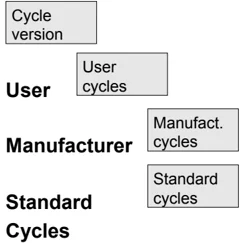
Press the desired vertical softkey
- "User cycles" or
- "Manufacturer cycles" or
- "Standard cycles"
The "Cycle version" horizontal softkey remains active.
All files of the type .com and .spf from the user, manufacturer or standard cycle directory are displayed in the "Version data" overview without the package lists.
Definitions
The definition files available on the NCK can be displayed in a separate "Version data definitions" overview by pressing the "Definitions" horizontal softkey. All the definition files from the DEF.DIR directory in the data management then appear in this overview.
You can change to another version display by pressing a different horizontal softkey.
The version information can be sorted according to the proposed criteria in either ascending or descending order.
The sorted and unsorted version displays of the displayed definitions are saved as follows:
8
Diagnostics operating area 8.5 Calling theversion screen 8
8.5.3 Cycle version output
Function
You can save the contents of the version displays for cycles in a separate log file.
Sequence of operations
To create a separate log file for the following version contents, press the "Save versions" vertical softkey in the "Version data type cycles" version display:

File: CYP.COM CYP_DET.COM ALLCYCLE.COM CUS.COM CMA.COM CST.COM
Type: Package overview Details All cycles User cycles Manufacturer cycles Standard cycles
When the data have been saved, the following message appears: "File stored!" " ⇒ Services:\Diagnostics\LogFiles\xxx.com. xxx stands for the file name preceding the extension .COM for each type.
8.5.4 Displaying loadable compile cycles
Function
Loadable compile cycles (CC) are an optional extra. The functionality must be enabled explicitly. If loadable compile cycles are available on your NCK, you can display them in a separate "Version data cycles" display under Service displays/Version/Compile cycles.
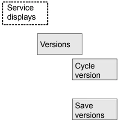
Sequence of operations
Compile cycles are loaded when you initiate an NCU reset and can then be displayed under Service displays/Version/Compile cycles.

8 Diagnostics operating area 01/2008 8
8.5 Calling theversion screen
Version Öffnen Sie im Menü "Serviceanzeigen" das Fenster "Version". The "Compile cycles" softkey appears.
Compile cycles Press the "Compile cycles" softkey.
Display loaded CC All loaded files of the type .elf are displayed in the "Version data compile cycles" overview.
You can check the storage location of the loadable compile cycles in the Services operating area in the "Manage data" main screen. You can copy the available loadable compile cycles from here onto an installed NC card. Other storage locations, such as any external drive, e.g. disk drive or network drives 1 to 4, are supported.
Display non-loaded CC All non-loaded files of the type .elf can also be displayed in the "Manage data" main screen. To do this, select the appropriate directory. You can display all the main properties of an individual compile cycle by selecting any individual file with the extension .elf.
Properties Press the "Properties" softkey The horizontal and vertical softkey bar changes and a "Properties" window, such as the one below for NC card, appears.
\begin{tabular}{|l|l|l|l|} \hline \multicolumn{4}{|l|}{\textbf{Properties}} \ \hline Path & :\textbackslash NCcard\textbackslash LoadableCompileCycles & & \ Name & :CCMCSC & Date: & Time \ extension & :ELF & Length: & Loaded: \square \ Type & :Loadable compile cycle & & \ \hline \multicolumn{4}{|l|}{\textbf{Access authorization}} \ \hline Read: Write: & Enable: & List: & Delete: \ \hline \multicolumn{4}{|l|}{\textbf{Contents: Loadable compile cycle}} \ \hline \multicolumn{4}{|l|}{Version: MCSC Coupling axes Machine \quad Time \quad Date} \ \multicolumn{4}{|l|}{Advance version of compile cycle (Preliminary)} \ \multicolumn{4}{|l|}{Interface: 001.001@Interfaces=002.000 @TChain=001.000} \ \hline \multicolumn{4}{|l|}{\textbf{Current access authorization access level:}} \ \hline \end{tabular}
8.6 Interrogating the PLC status
Function
You can obtain information about the current states of the following memory locations of the PLC and change them if necessary:
Inputs:
- Input bit (Ex), input byte (EBx)
- Input word (Ewx), input double word (Edx)
Outlets:
- Output bit (Ax), output byte (Abx)
- Output word (Awx), output double word (Adx)
Bit memories:
- Memory bit (Mx), memory byte (MBx)
- Memory word (MWx), memory double word (MDx)
Timers:
- Time (Tx)
Counters:
- Counter (Cx)
data:
- Data block (DBx), data bit (DBxx), data byte (DBBx),
- data word (DBWx), data double word (DBDx)
Format:
- B = binary
- H = hexadecimal
- D = decimal
- G = floating comma (for doublewords)
| Operand | Example | Read | Write | Format | Value | Range |
|---|---|---|---|---|---|---|
| Inputs | I 2.0 | Yes | Yes | B | 0 | 0-127 |
| IB 2 | B | 0101 1010 | ||||
| H | 5A | |||||
| D | 90 | |||||
| Outputs | Q20.1 | Yes | Yes | B | 1 | 0-127 |
| QB 20 | B | 1101 0110 | ||||
| H | D6 | |||||
| D | 214 | |||||
| Bit memory | M 60.7 | Yes | Yes | B | 1 | 0-255 |
| MB60 | B | 1101 0110 | ||||
| MW 60 | H | B8 | ||||
| D | 180 | |||||
| Timers | T20 | Yes | No | B | 0-31 | |
| H | ||||||
| D | ||||||
| Counter instructions | C20 | Yes | Yes | B | 0-31 | |
| H | ||||||
| D | ||||||
| DB / Data byte | DB3.DBB9 | Yes | Yes | H | A | 0-255 |
| D | 10 | 0-255 | ||||
| B | 000 0000 0000 1010 |
SINUMERIK 840Di sl/840D sl/840D Operating Manual HMI-Advanced (BAD) - □□/□□□□ Edition
8 Diagnostics operating area
8.6 Interrogating the PLC status
i PAGE DOWN PAGE UP . In HMI, the "Page" keys can be used to scroll up and down.
8.6.1 Changing/deleting a value
 Function
The values of operands can be changed.
 Sequence of operations
The "Diagnostics" operating area is selected.
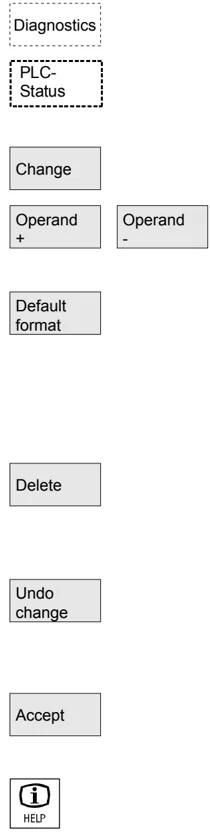
Diagnostics PLC-Status Press the "PLC status" softkey. The first operand screen form appears. The vertical softkey bar changes.
Change Cyclic updating of the values is interrupted.
Operand + Operand - You can increase or decrease the address of the operand by 1 place at a time.
Default format Softkey allocation A selection window appears. You can preset the format fields to "B" (binary), "H" (hexadecimal), "D" (decimal) or "G" (floating point). Change the operand, the format or the value.
Delete Delete: The entries for the selected operand (formats and values) are deleted. A query window is opened.
Undo change Undo changes: Cyclic updating is continued; the entered values are not transferred to the PLC.
Accept Accept: The entered values are transferred to the PLC. Cyclic updating is continued.
HELP Press the "information key". A description of the permissible input syntax for the PLC status display is overlaid.
8.6.2 Assign symbolic PLC addresses
Function
PLC data can also be edited via symbols. To do this, the symbol tables and texts for the symbols in the PLC project must have been suitably prepared and made available in the HMI.
Additional information
The program PlcSymbolsGenerator.exe and its description are located in the PLC tool box. It creates the files with symbols and language-dependent texts in the representation required for the HMI.
Prerequisites
Preparation of PLC data:
- Save the files created with PlcSymbolsGenerator.exe in the Services operating area under path: Diagnostics/PLC Data (F:\DH\DG.DIR\PLC.DIR\ ) with the following predefined names and extensions:
- PlcSym.SNH (symbols)
- PlcSym_.SNT (texts e.g. PlcSym_GR.SNT)
- NC RESET or reboot HMI to activate file
- Only for M:N configurations: There must be an entry which makes the symbols available in netnames.ini for each addressable NCU.
References
For more information, please refer to: Commissioning Manual HMI-Advanced (IM4)
Languages
If the texts (symbol comments) are stored for multiple languages, you can also change language to work with texts in the other languages.

8 Diagnostics operating area
8.6 Interrogating the PLC status
Sequence of operations
The "Diagnostics" operating area is selected. If the above listed requirements are met, the PLC symbol softkey is displayed.
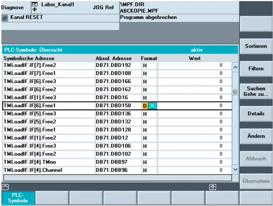
The following are represented in the table from left to right:
- Symbolic address
- Absolute address
- Format
- Value
Select a sort option from:
Depending on your selection, sorting takes place on column one or column two in ascending or descending alphabetical order to make it easy to find a symbol or address. "As in symbol table" means: In the same sequence as the symbol table in the PLC project.
Select the categories of symbols/addresses that you want to display. Press OK to activate the filter. Filters are retained after you exit screens/operating areas and after reboot.
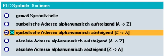
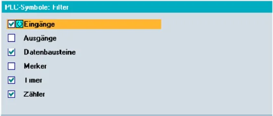
8.6 Interrogating the PLC status
After entering a search term and search direction, the section of the table is displayed with the focus on the symbol/absolute address if it was found.
The search is performed in the following sequence: absolute addresses, symbols.
When you enter the search term in the "Address" field, take care to enter the correct notation. Press OK to start the search.
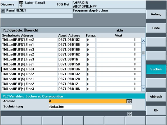
If the search term is not found, the dialog box remains open for a new search. After you change screens, the search term and search direction are retained in the dialog box
Press this softkey to jump to the beginning of the symbol table.
Press this softkey to jump to the end of the symbol table.
All information is displayed for the selected address or symbol in the following representation:
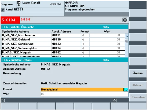
If relevant texts are available in the PLC project, they are displayed here as "description".
8 Diagnostics operating area 01/2008 8
8.6 Interrogating the PLC status
Change You can change the value of the symbol that is currently displayed in detail. The input marker is positioned on Value. Value input is completed by pressing the Enter key; however, the values are only activated when the "Accept" softkey is pressed. You can also choose a more suitable display format.
Accept The entered value is transferred to the PLC interface.
Change You can change the value for the selected symbol. Value input is completed by pressing the Enter key; however, the values are only activated when the "Accept" softkey is pressed. You can also choose a more suitable display format. Before pressing the Accept softkey to validate the data changes, you can modify any number of symbol values in sequence.
Accept The previously entered values are transferred to the PLC interface.
Symbols in the status screen
If the above mentioned requirements are met, the additional "Symbol" softkey is displayed in the PLC status screen.
Diagnostics PLC - status
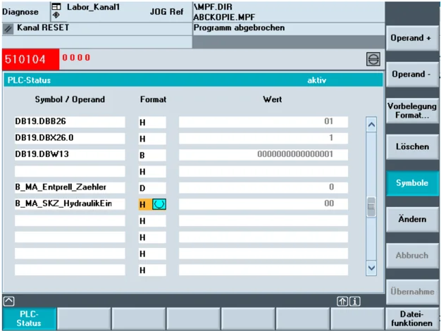
Symbols You can use the softkey to switch between absolute addresses and symbols for inputs and display in the status screen. If a symbol is selected, the "Operand+" and "Operand-" softkeys defined for absolute addresses are not available. Otherwise, the above description for PLC status also applies to the status screen.


8.6.3 Select operand screens for PLC status
Function
You can save the operands entered in the "PLC status" window to a file or read in a back-up list of operands.
Sequence of operations
The "Commissioning" operating area is selected.
Press the "PLC" softkey. The horizontal and vertical softkey bars change.
Press the "File functions" softkey. The vertical softkey bar changes.
Enter the name of the file in which you wish to save the operands. You can select existing back-up files from a list.
All the following functions refer to the file name entered:
The selected operand back-up file is deleted.
The selected operands are saved to the specified file.
The selected operand file is loaded to the "PLC status" window for processing.
If errors occur during transfer of the machine data, these are entered in an error log.
The error log is transfer-specific, i.e. it is cleared before each new transfer.
The ASCII editor is called with the selected file. You can now edit the operand back-up file.

8 Diagnostics operating area 01/2008 8.6 Interrogating the PLC status 8
8.6.4 File functions

File functions
You can use the file functions to manage operand screens.
Sequence of operations
Diagnostics PLC status
The "Diagnostics" operating area is selected.
Press the "PLC status" softkey. The first operand screen form appears. The vertical softkey bar changes.
File functions
Press the "File functions" softkey. The "File functions" window opens.
Enter the file name of the desired operand screen form or position the cursor on the desired operand screen form in the list.
Delete
The selected operand screen form is deleted.
Save
The current contents of the PLC status are saved in the selected operand screen form.
Load
The contents of the selected operand screen form are loaded to the PLC status.
Additional information
The operand screen forms are ASCII files.


Commissioning operating area
- 9.1 Startup main screen 9-430
- 9.2 Machine data 9-432
- 9.3 NC 9-434
- 9.4 PLC 9-435
- 9.5 Optimization/test (SINUMERIK powerline) 9-436