4
Machine operating area 4.4 JOG mode
Explanations relating to the JOG main screen
Displays the addresses of the existing axes with the machine axis identifier (MCS) or with the geometry axis identifier (WCS). (see also Section "Toggle between machine/workpiece coordinate system (MCS/WCS)")
- WCS X2* Y2* Z2*
Machine manufacturer
Machine data are used to define whether the programmed frames are to be calculated when displaying the WCS (settable zero system = SZS display).
Please consult the documentation provided by the machine manufacturer!
- If the axis identifier can only be displayed in an abbreviated form, this is indicated by the character,.
- If you traverse an axis in the positive (+) or negative (-) direction, a plus or minus sign is shown in the relevant field. The axis is in position if neither + nor - is displayed in the position display.
Position 0.0 0.1 -0.1 1.1 0.0
The actual position of each configured axis in the machine (MCS) or work (WCS) is displayed in these fields. The sign is only displayed for negative values.
Repos. offset 0.0 0.1 -0.1 1.1 0.0
If the axes are traversed in the "Program interrupted" status "in "JOG" mode, the path traversed by every axis with respect to the point of interruption is displayed in the REPOS offset.

4 Machine operating area 01/2008 4
4.4 JOG mode
Spindle
 Spindle window (if spindle is available)
The window contains the setpoint and actual values for the spindle speed, the spindle position, setting of the spindle override switch and spindle output.
Nibbling The spindle window is replaced by a nibble window if the "Nibbling" technology option is set. The active function, if any, appears at the top left in the window header:
- PON Punching ON
- SON Nibbling ON
- SPOF Punching/nibbling OFF
Feedrate
 Feedrate window
Display of the setpoint and actual value of the feedrate as well as the position of the feedrate override switch (in %). The actual setpoint to be traversed is dependent on the override switch.
When G00 (rapid traverse movement) is programmed, the rapid override value is displayed.
If the feedrate is not enabled, the symbol "Feedrate not enabled" is output in the feedrate window. (FST is not indicated in the "program control display" field).
Tool
 Tool window
Display of active tool offset (e.g., D1), tool currently in use (T no.), preselected tool (on milling machines) plus currently active motion commands (e.g., G01, SPLINE, ...) or
tool radius compensation not active (e.g., G40).
The following values are displayed:
- The "Path section" and "Stroke rate" are displayed in reverse video if you have programmed the automatic block division with "Path section length" or "Number of path sections".
- The "delay time" can only be displayed if you have set "Punching with delay time".
Zoom act. val. Increases the size of the actual-value display.
4 01/2008 Machine operating area 4.4 JOG mode 4
4.4.2 Traversing axes
Traverse rate The initial settings for traverse rate and feed mode are stored in setting data for JOG mode. Traverse rates are defined by the machine manufacturer. The default setting for the feedrate is mm/min. See operating area "Parameters/Setting data/JOG data".
Sequence of operations "JOG" mode is selected in the "Machine" operating area.
Traversing axes Using the "Inc" (increment, see Subsection 2.2.2) function, manually traverse the selected axis in preset increments in the appropriate direction by pressing an "Axis key" repeatedly:
- [.] Variable increment can be set via the "Inc" softkey.
- [1], [10], ..., [10000] fixed increment
Turning machine: Press the "Axis" keys.
If necessary, set the rate with the override selector.
If you press "Rapid traverse override" at the same time, you can traverse the axis in rapid traverse mode.
Milling machine: Select the axis to be traversed and then press the "-" or "+" key.
Feedrate and rapid traverse override switches can be operative.
One or several axes can be selected at the same time (depending on PLC program).

4 Machine operating area
4.4 JOG mode
Additional information
- When the control is switched on, the axes can be traversed right up to the limits of the machine as the reference points have not yet been approached and the axes referenced. Emergency limit switches might be triggered as a result.
- The software limit switches and the working area limitation are not yet operative!
- The feedrate enable must be set (FST display must not light up in the program control display).
Machine manufacturer
If no advantage is to be gained from moving several axes simultaneously, the machine manufacturer must implement the appropriate interlock in the PLC program.
4.4.3 Inc: Increment
Function
The "Inc" (increment) function can be used to enter a settable increment value for Inc variable traversing.
Sequence of operations
"JOG" mode is selected in the "Machine" operating area.
INC The "Increment" window appears on the screen.
Enter the desired increment.
[VAR] Press this key in manual mode together with the "Axis" key to traverse the selected axis in the appropriate direction in accordance with the increments set above (see also Section "Traversing axes"). Increment keys with preset increment sizes are temporarily inoperative.
4.4.4 REPOS (repositioning)
Function
After a program interruption in Automatic mode (e.g., to take a measurement on the workpiece or to compensate tool wear values or after tool breakage), you can retract the tool manually from the contour after selecting "JOG" mode. In such cases, the control stores the coordinates of the point of interruption and displays the path distances traversed by the axes in "JOG" mode as a "Repos" offset in the actual value window.
"Repos" offsets can be displayed in the machine coordinate system (MCS) or workpiece coordinate system (WCS).
Sequence of operations
"JOG" mode is selected in the "Machine" operating area. The axes have been moved away from the point of interruption.
Select machine function "Repos".
Turning machine: Press the "Axis" keys.
Milling machine: Select the axis to be traversed and then press the "-" or "+" key.
It is not possible to overtravel the point of interruption. The feedrate override switch is active.
Warning
The rapid traverse override key is active. Non-compensated Repos offsets are compensated with programmed feedrate and linear interpolation on switchover to Automatic mode and selection of NC Start.

4 Machine operating area 01/2008 4
4.4 JOG mode
4.4.5 SI (Safety Integrated): User agreement
Function
If the option "user agreement" is installed on the NC, you must enable or disable the function depending on the keylock switch position in "Approach reference point" mode.
User agreement can only be granted if keylock switch position 3 or higher applies in respect of the access level.
The displayed values always refer to the machine (MCS).
Sequence of operations
"JOG Ref" mode is selected in the "Machine" operating area. The channel to be referenced is already selected.
Press the "User agreement" softkey. The "Confirm Machine Positions" window is opened. The machine axes in the MCS are displayed, together with the current position and a checkbox for activating/deactivating user agreement.
Machine axes that do not have to be referenced are shown inverted: With their current position, but without check box.
Position the cursor on the desired machine axis.
Activate or deactivate user agreement for the selected machine axis via the "Toggle" key.
Check whether the axis is referenced. If not, error message "Please reference axis first" is output. User agreement cannot be activated for the axis until it has been referenced.

4
Machine operating area 4.4 JOG mode
Additional information
The user agreement function is only provided if user enabling is required for at least one axis of the channel.
References
/FBSI/, Description of Functions SINUMERIK Safety Integrated.
4.4.6 Scratching

Notes
Depending on the machine data configuration, two scratching modes are possible.
Function
You can determine the work offset by "scratching" the workpiece, taking an (active) tool and, if necessary, the basic offset into account. A window is provided for the "Scratching" function.
Sequence of operations
- Press the "Scratch" softkey: The softkey will only be made available if you are entitled to use it (machine data).
- The active plane is displayed and can be altered.
- The active NV is displayed and can be changed.
- The active tool is displayed. No tool is displayed if none is active (message).
S cratching

4 Machine operating area 01/2008 4
4.4 JOG mode
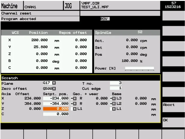
Meanings of columns in the "Scratch" window:
- "Offset": Current value of offset to be determined. The coarse offset is displayed; the fine offset is taken into account and remains valid.
- "Position setpoint": Input of subsequent position setpoint for scratched edge.
- "Approach direction": selection fields for positive/negative approach direction

-
Use the cursor to select the first axis to be traversed in the "Scratch" display. Selected axes are automatically marked in parallel in the actual value window.
-
Traverse the axis up to the workpiece, enter the chosen position setpoint (e.g., "0") and press the "Input" key. The offset is then calculated. Repeat the process for other axes.

- Press "OK" to transfer all values to the selected WO. The offset is always calculated in relation to the current work (WCS).

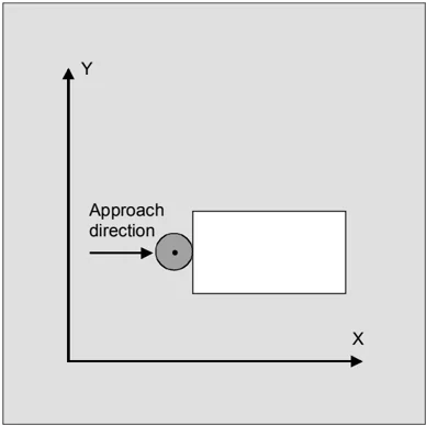
- To ensure that allowance is made in the tool geometry (or the tool base dimension), position the cursor in the "Approach direction" column on the axis to be altered and press the "Toggle key" so that the desired approach direction is visible.
Machine operating area 4.4 JOG mode
Example 1:
Set "+R" with toggle key.
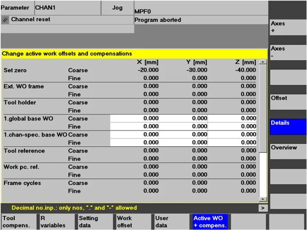
The figure below shows how system frame $P_SETFR is displayed as the line "Set work offset".

Toolholder
If a toolholder is active in the present system, it is displayed in the G function window as "TCARR=n" (n = 1 or 2).
4 Machine operating area 01/2008 4
4.4 JOG mode
S swivel adjustment
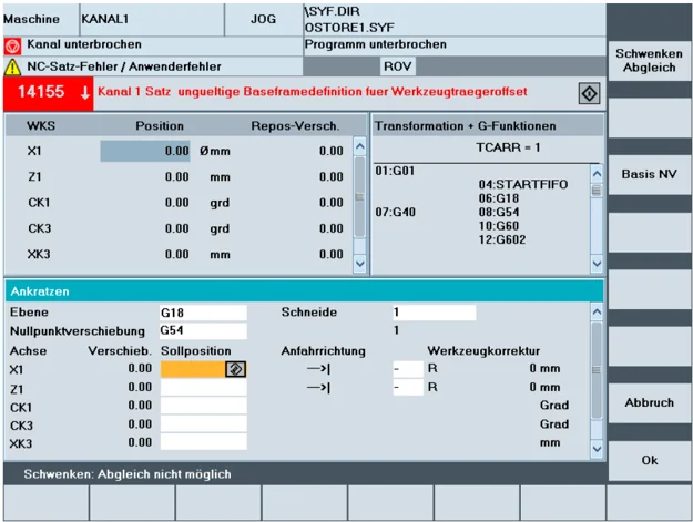
With scratching in a swiveled level with rotary axes without encoder, the "Swivel adjustment" vertical softkey appears in addition to the toolholder information in the "Transformations + G functions" window. Upon activation, the NC updates the toolholder data after scratching. If this operation is successful, "Swivel adjustment completed" is output in the message line. If an error occurs, e.g. the channel is in "active" state or the connection with the NC is disrupted, "Swiveling: adjustment not possible" is displayed in the message line.
4.4.7 Displaying system frames
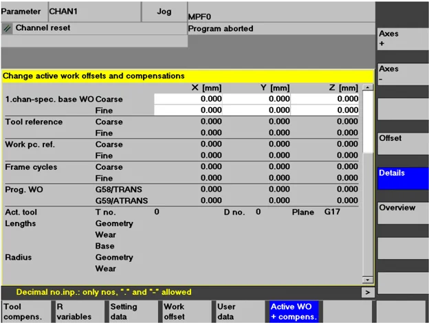
If system frames have been activated via MD, they can be displayed via the Parameters operating area, Active WO + Override, Details.
The following assignment is applicable:
$P_SETFR System frame for actual value setting, scratching $P_EXTFR System frame for work offset external $P_PARTFR System frame for TCARR and PAROT $P_TOOLFR System frame for TOROT and TOFRAME $P_WPFR System frame for workpieces $P_CYCFR System frame for cycles
Both the offset set via frames (coarse and fine) and the rotation and mirroring defined there are displayed. Display is according to the position in the frame chain.
You can choose between the system frames and basic frames by scrolling through the desired section.


4
Machine operating area 4.4 JOG mode
4
The following figure shows an example screen layout:

Protection levels for system frames
The machine manufacturer or user can assign the appropriate protection levels for system frames as well as for individual functions and data areas using display machine data.
Default: These machine data are assigned protection level 7 by default during the standard commissioning procedure. This means that access is granted to all these data areas and functions when the keylock switch is in the 0 position. If required, these protection levels can be changed by the machine manufacturer or user. Protection levels 0 to 3 can also be entered.
4 Machine operating area 01/2008 4
4.4 JOG mode
Protection levels are available for the following system frames:
Note:
In the case of SetFrame, the same machine data applies as for settable work offsets, as this practically does constitute a work offset. This also applies to SetFrame fine offset, in respect of which no user intervention is permitted. For fine offset of the settable work offsets, there is a dedicated machine data:
9203 $MM_USER_CLASS_WRITE_FINE. The associated protection level is generally lower than for coarse offset.
Further information:
Set zero point corresponds to $P_SETFR
Ext. WO frame corresponds to $P_EXTFR
Toolholder corresponds to $P_PARTFR
Tool reference corresponds to $P_TOOLFR
Workpiece ref. corresponds to $P_WPFR
Cycles corresponds to $P_CYCFR
See also Subsection 4.4.6
4.5 MDA mode
4.5.1 Function and main screen
Function
In "MDA" (Manual Data Automatic) mode, you can write part programs block by block and execute them. You can transfer the required motions as single part program blocks to the control using the operator panel. The control processes the entered program blocks when you press the "NC Start" key.
Caution
The same safety interlocks must be applied as used in fully automatic operation. The same preconditions must be fulfilled as for fully automatic operation.
The automatic functions (traverse blocks) are active in "MDA" mode.
Teach In
The functions associated with "JOG" are active in submode "Teach-in" and can be accessed via an MCP key. You can therefore create and store a program in the input and manual modes by alternating between "MDA" and "Teach-in".
You can use the editor to edit the program blocks in the MDA window. You can view blocks that have already been executed by paging upwards.
Blocks that have already been executed can only be edited in the Reset state. Further blocks can be added with "Input".
Blocks can only be input and executed with the channel in the "Channel Reset" or "Channel interrupted" state.
The program created in MDA mode can be saved in the part program directory (MPF.DIR).

4 Machine operating area
4.5 MDA mode
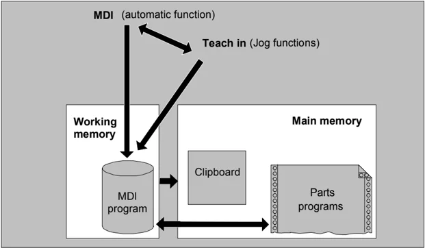
The "MDA" main screen contains values relating to position, feedrate, spindle and tool as well as the contents of the MDA buffer.
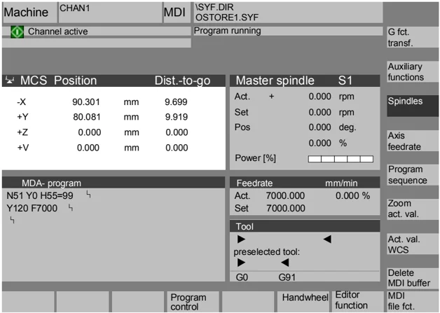
Explanation of "MDA" main screen
| Save MDA prog. | As with the JOG main screen, the actual value window, spindle window, feedrate window and tool window are output. |
|---|---|
| Editor functions | The "Store MDA program" softkey copies the MDA program to the clipboard. |
| MDA file fct. | Press this softkey to access functions via vertical softkeys that will facilitate the editing process: Overwrite, Mark, Copy, Paste, Delete, Find, Find Next, Position. You can save the MDA buffer contents or copy a part program to the MDA buffer for editing in MDA or Teach-in. |
4
Machine operating area 4.5 MDA mode
Vertical softkeys
Like the JOG main screen, the MDA main screen contains softkeys "G Fct.+Transf.", "Auxiliary functions" and "Spindle" (if spindle is configured).
The contents of the MDA program in the NC are erased.
Delete MDA buffer
4.5.2 Saving the program, file function
Function
You can use the MDA file function to
- Save the contents of the MDA program to a file or
- Read a part program to the MDA clipboard to edit it in MDA or Teach-in mode.
Sequence of operations
"MDA" mode is selected in the "Machine" operating area.
The program overview of "Part programs" is opened, a dialog window also appears.
The new file is then displayed in the program overview.
MDA file function
Read in MDA
The program overview of part programs is displayed. From the list of programs, select the one that you wish to copy to the MDA buffer with "Read in MDA". This can now be edited accordingly.
Save MDA progr.
The system will ask you to enter a name for the file to be saved to the MDA clipboard. The program is saved/stored as a part program (MPF) under the name you have entered in the part programs directory.

4 Machine operating area 01/2008 4
4.5 MDA mode
4.5.3 Teach in
Function
With the "Teach-in" function, part programs (main programs and subprograms) for motion sequences or simple workpieces can be created, edited and executed by approaching and then storing positions in combination with the "MDA" function.
There are two possible methods of writing programs with "Teach-in" and "MDA":
- Manual positioning
- Manual input of coordinates and additional information
Both entry of blocks (input, delete, insert) and automatic insertion by manual approach of positions are possible only at points that have not yet been executed.
1. Manual positioning
Sequence of operations
"MDA" mode is selected in the "Machine" operating area.
Submode "Teach-in" is selected. After selection of the function, the cursor is located in the first blank line of the "Teach-in program" window.
Turning machine: Press the "Axis" keys.
Milling machine: Select the axis to be traversed.
then press the "-" or "+" key.
The axis name and the path being traversed are displayed continuously on the screen in the "Teach-in program" window. The axis identifier and axis positions are transferred to the MDA program as values referred to the workpiece coordinate system.
4-130 © Siemens AG 2008 All rights reserved.
4 01/2008 Machine operating area 4.5 MDA mode 4
Save position values: Enter the additional functions (e.g. feedrates, auxiliary functions, etc.) in the program (if permitted).
Using MDA file functions, you can save the MDA program in the "Part programs" directory (MPF.DIR).
Using the edit functions of the vertical softkeys, you can execute the following program block functions: Overwrite, Select, Copy, Paste, Delete, Find, Find Next and Position.

When you switch to "MDA" mode and press "NC Start", the corresponding traversing motions and additional function entries are executed as program blocks. While the program is being processed, the blocks traversed by the NC are displayed in the "Current block" window.
2. Manual input of coordinates
Sequence of operations
"MDA" mode is selected in the "Machine" operating area.
Save position values/additional functions: Transfer the coordinates of the traversing positions plus any additional functions (preparatory functions, auxiliary functions, etc.) to the program by entering them in the "MDA program" window.
Additional information
- Any change to the work offset will cause the axis to carry out compensating movements when you press NC Start.
- In the case of G64, the end point response will differ when the part program is executed in "Automatic" mode.
- All the G functions can be used.
- When using special kinematics or robots, the positions of the STAT machine and rotary axis TU are displayed in addition to the positions in the workpiece coordinate system.

4.6 Automatic mode
4.6.1 Function and main screen
Function
You can execute part programs fully automatically in "Automatic" mode; this is the normal operating mode for part machining.
Preconditions
The following conditions must be fulfilled before you can execute part programs:
- You have already synchronized the control measuring system with the machine (i.e. "approached" reference points).
- You have already downloaded the associated part program to the control.
- You have checked or entered the necessary offset values, such as work offsets or tool offsets.
- The required safety interlocks are already active.
Position, federate, spindle and tool values as well as the workpiece program are displayed in the "automatic" main screen.
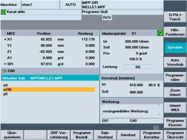
Explanation of main screen
The following windows are displayed: Actual value window, spindle window, federate and tool window.
4 01/2008 Machine operating area 4.6 Automatic mode 4
Horizontal softkeys
Program overview The workpiece or program overview is displayed. In this area, it is possible to select programs for execution. The memory space available on the hard disk and in the NCU is displayed in the footer.
Vertical softkeys
Program blocks In addition, the window "program blocks" is displayed. The current block is highlighted while the program is running. The name of the program to which the blocks on the screen belong is output in the window header.
Program levels The "program levels" window is displayed after pressing the softkey "program levels". The program nesting depth (P = number of passes) is displayed.
Program execution In program operation, it is possible to toggle between the window "Program levels" and "Program execution"
Program blocks 9 program blocks of the current program are displayed together with the current position in the part program. In running operation, the 3-block display (softkey "program execution") and the multi-block display (softkey "program blocks") can be selected.
Additional information
The other softkeys are described in the sections below.

4 Machine operating area 01/2008 4
4.6 Automatic mode
4.6.2 Program overview
Function
After selection of a workpiece or program overview, individual workpieces or programs can be enabled or disabled for execution.
Sequence of operations
"AUTO" mode is selected in the "Machine" operating area. The appropriate channel is selected. The channel is in reset state. The workpiece/program to be selected is in the memory.
Program overview An overview of all workpiece directories/programs that exist is displayed.
Position the cursor on the desired workpiece/program.
Vertical softkeys
Select the workpiece/program for execution:
Selection The name of the selected workpiece is displayed on the screen in the "Program name" field at the top. The program is also loaded and selected for processing.
Change enable The selected workpiece/program is enabled (X) or disabled (no "X"). A selection can only be made when the workpiece/program is enabled.
Explanation of other softkeys:
All existing programs of a particular type are displayed via the horizontal softkeys:
Work-pieces Display of all existing workpiece directories
Part programs Display of all existing part programs
Sub-programs Display of all existing subprograms
Standard cycles Display of all existing standard cycles
4
Machine operating area 4.6 Automatic mode 4
\begin{tabular}{ll} User cycles & Display of all existing user cycles \ Manufact. cycles & Display of all existing manufacturer cycles \ \end{tabular}
4.6.3 Loading and unloading the workpiece/part program
Function
Workpieces and part programs can be stored in the NC working memory ("Load") and erased from this memory again ("Unload") after they have been executed. In this way, it is possible to prevent the NC working memory from becoming unnecessarily overloaded because programs that are no longer required can be erased immediately.
Sequence of operations
The "Machine" operating area is selected.
Program overview The "Program overview" opens. The vertical softkey bar changes.
Position the cursor in the directory tree on the workpiece/part program that you wish to load.
Load HD->NC The selected workpiece/part program is loaded from the hard disk into the memory of the NC. It is erased from the hard disk.
Enable If the enable command (X) is set, the workpiece can be machined.
Unload NC->HD The highlighted workpiece/part program is loaded from the NC memory to the hard disk. The workpiece/program is erased from the NC memory.
Execute fr. hard disk If a program requires more memory than the NC can provide for execution, then it can be executed from the hard disk without loading it completely into the NC.

4 Machine operating area 01/2008 4
4.6 Automatic mode

Additional information
Workpieces/part programs that have been loaded into the NC memory are marked with ("X") in the "Loaded" column in the workpiece/program overview.
4.6.4 Protocol: Program loading list

Function
Error list: Display of previously loaded programs if errors have occurred during loading.

Sequence of operations
The "Machine" operating area is selected.
Program overview
Log
The "Program overview" opens. The softkey bars change. Press the "Log" softkey. The "Job log for program overview" window is opened.
4
Machine operating area 4.6 Automatic mode 4
4.6.5 Executing from the hard disk
Function
If a program requires more memory than the NC can provide for execution, then it can be loaded continuously from the hard disk.
Sequence of operations
The "Machine" operating area is selected.
Program overview The "Program overview" opens. The vertical softkey bar changes. Select the program you wish to execute with the cursor (enable (x) must be set).
Execute fr. hard disk The highlighted program is loaded continuously to the NC working memory during execution.
Cycle Start Press "NC Start".
The program remains stored on the hard disk while the "Execute from hard disk" function is in progress.
External programs The "External programs" window is opened. The "Status" field indicates what percentage of the program has been loaded from the hard disk.
Additional information
Programs which are executed from the hard disk are marked with "EXT" in the program overview. The identifier "EXT" does not disappear until a different part program is selected in this channel.
When executing from the hard disk and with EXTCALL, only the 3-block display (softkey "program execution") is possible. This setting applies for the single block or NC stop status.


4 Machine operating area
4.6 Automatic mode
4.6.6 Accessing an external network drive
Function
With the SINDNC software, you can link your control to external network drives or other computers. This makes it possible, for example, to execute part programs from other computers.
Prerequisite:
- The SINDNC software is installed.
- The computer or drive which you want to link up to is accessible/enabled.
- A connection to the computer/drive has been established.
- The softkeys to select the drive/computer connection were configured using machine data
- Separate display machine data which define the access rights to external drives exist for the Machine and Program operating areas See: Commissioning Manual HMI-Advanced (IM4)
Sequence of operations
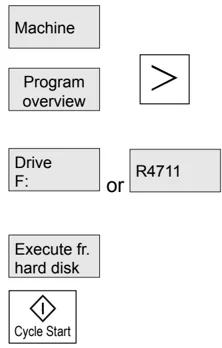
You can access the softkeys (configured) for the external drive or computer in the Machine operating area via the "Program overview" softkey and the "ETC." key. Horizontal softkeys 1 to 4 are reserved for external execution. The vertical softkey bar changes.
When you press a softkey, e.g., "Drive F:" or "R4711" the Explorer appears on the screen with the data of the external drive, e.g. "Drive F" or of computer "R4711". Select the program that you want to execute with the cursor and then press the "Execute from hard disk" softkey. The program starts when you press "NC Start".
4
Machine operating area
4.6 Automatic mode
Softkey definitions
Press the "Program overview" softkey in the Machine (and Program) operating area to access the first three softkeys configured for external network drives. If you have configured four softkeys, the fourth one is displayed in the More bar when you press the "ETC" key. If no softkeys are configured for external drives, the "Standard cycles", "User cycles" and "Manufacturer cycles" softkeys can be found in the appropriate places in the horizontal softkey bar.
Program call from the part program: EXTCALL
It is possible to access files on network drives from a part program using the EXTCALL command.
The programmer can set the source directory in the part program in setting data
SD 42700: EXT_PROG_PATH, then specify the file name of the subprogram to be loaded in the EXTCALL command.
The following supplementary conditions must be taken into account with EXTCALL calls:
- With EXTCALL, you can only call files with the MPF or SPF extension from a network drive.
- DOS naming conventions must be used for the files and paths: Max. 25 characters for the name, 3 characters for the file extension.
- A program unit is found on a network drive with the EXTCALL command if
- The search path in SD 42700: EXT_PROG_PATH points to the network drive or a directory contained on the network drive. The program must be stored directly on that level, no subdirectories are searched.
- The correct location of the program is specified in the EXTCALL call itself by means of a fully qualified path that can also point to a subdirectory of the network drive.
- The search path is not restricted by means of SD 42700: EXT_PROG_PATH.
References
For further information about the EXTCALL command, please refer to: /PGA/ Programming Guide Advanced, Chapter 2. /FB/, K1 Description of functions "Execution from external source"