5 Parameters operating area
5.7 Define user data
5.7.2 Editing/finding user data
Sequence of operations
Press the "User data" softkey. The "Global user data" window is displayed. The vertical softkey bar changes.
You can toggle between windows
- "Global user data" (GUD)
- "Channel-specific user data" and
- "Program user data"
Program-global variables (PUD) and local variables (LUD) are displayed. You can scroll up and down in the list using the "Page" keys.

Edit user data Position the cursor on the user data that you wish to edit and enter a new value. New values are automatically accepted.
Searching user data Press the "GUD +" and "GUD - " softkeys to scroll through user data from GUD 1 to GUD 9.
The "Select global user data" window is opened. The following values are permissible:
- 1 = SGUD (Siemens)
- 2 = MGUD (machine manufacturer)
- 3 = UGUD (machine user)
- 4 ... 9 = GD4... GD9 (additional, e.g., grinding cycles, etc.)
The selected data are displayed in the "Global user data" window.
Additional information
Up to 200 characters can be entered/displayed for GUD of type String.


5 01/2008 Parameters operating area 5.7 Define user data 5
Find Press the "Find" softkey. The "Find user data" dialog window appears on the screen.
The data name or a character string within the name can be entered as the search target. The cursor must be positioned on the user data to be found.
Find next The next user data with the initial identifier searched for is displayed.
User data of types AXIS and FRAME are not displayed. Only those local user data that still exist in the execution chain of the control are displayed.
The list of local user data for the display window is updated every time "NC Stop" is actuated. The data values are updated continuously. Before global user data definitions can be made operative in the control, it may be necessary to set machine data.
Additional information
How to define and activate user data is described in chapter Service operating area

5 Parameters operating area 01/2008 5
5.7 Define user data
5.7.3 Activate user data (GUD)
Function
Create a definition file for user data:
- In the "Services" operating area using the "Manage data" softkey
- in the "Definitions" directory
Response
If a definition file is edited in the NC, when exiting the Editor you are prompted whether the definitions are to be activated.
Example: "Do you want to activate the definitions from file GUD7.DEF?"
OK "OK" \rightarrow A query is displayed asking if the currently active data should be saved. "Should the previous definition data be retained?" "OK" \rightarrow The GUD blocks of the definition file to be edited are saved, the new definitions are activated and the saved data are imported again.
Abort "Abort" \rightarrow The new definitions are activated, the old data are lost. "Abort" \rightarrow The changes in the definition file are discarded, the associated data block is not changed.
Unload
If a definition file is unloaded, the associated data block is deleted after a query is displayed.
Activate
If a definition file is loaded, a prompt is displayed asking whether to activate the file or retain the data. If you do not activate, the file is not loaded.
If the cursor is positioned on a loaded definition file, the softkey labeling changes from "Load" to "Activate" to activate the definitions. If you select "Activate", another prompt is displayed asking whether you want to retain the data.
5
Parameters operating area
5.7 Define user data
5
Data is only saved for variable definition files, not for macros.
Additional information
If there is insufficient memory space available to activate the definition file, then the file must be unloaded. After the memory size has been adjusted, the file must be loaded from the NC to the HMI and back again to the NC. The files are then activated.
Create a definitions directory
The definition files that the user can access are created and edited under the definitions directory _N_DEF_DIR:
- SACCESS.DEF (_N_SACCESS_DEF)
- MACCESS.DEF (_N_MACCESS_DEF)
- UACCESS.DEF (_N_UACCESS_DEF)
They do not need to be activated but are loaded to the passive file system of the NCK as follows: Press the "Manage data" softkey. The horizontal and vertical softkey bars change.
Manage data
New
Load the definitions directory in the HMI without modifying the existing access authorization.
Change write access
The data imported during the series commissioning are created and edited in the definitions directory _N_DEF_DIR:
- SACCESS.DEF (_N_SACCESS_DEF)
- MACCESS.DEF (_N_MACCESS_DEF)
- UACCESS.DEF (_N_UACCESS_DEF)
They do not need to be activated but are loaded to the passive file system of the NCK as follows:
References
Definition and creation of user data See /PGA/, Programming Guide Advanced

5 Parameters operating area 01/2008
5.8 Display system variables
5.8 Display system variables
Function
System variables can be used for a wide range of different functions (e.g. as variables or in synchronized actions).
The following options are available:
- View variables in a defined display (e.g., as a value or graphic characteristic) or
- Variable views:Manage
- Display variables of a view
- Define variable views
- Generate a log of the response of variables during a program run
- Define logs
- Start a log
- Manage a log
- Display log
Sequence of operations
The "System variable views" screen appears.
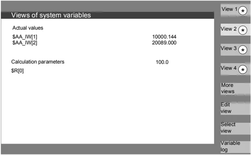
- The names of these softkeys can be customized.
This softkey opens a window in which views can be created or edited.
With "Select view", a dialog is started in which the user can select individual views or a file with several views.
5 01/2008 Parameters operating area 5.8 Display system variables 5
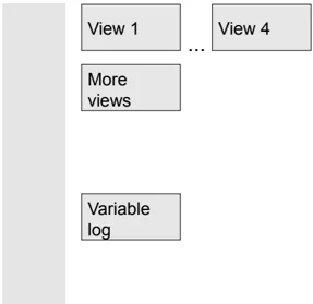
The names of the views of a file are assigned to the "View 1" to "More views" vertical softkeys. If a file contains more than five views, you can press the "More views" softkey to select the views stored in the file in blocks of four.
The "Logging system variables" display is selected with the "Variable log" softkey.
5.8.1 Creating variable views
Function
You can compile your own variable views.
The display of variables can be edited:
- Layout (e.g., 2 columns with 2 rows) or
- Properties (e.g. name, display type, input limits).
Sequence of operations
The "Edit view" softkey changes to edit mode.
With "Insert variable", a dialog box is opened in which the required system variable can be selected from a list using the cursor and the "Edit" key. The full name of the variable appears in the info line.
It is included in a new line or column in the view with the "Input" key. The variable is inserted after the cursor position.
Confirm your input with OK.
By selecting the "Insert user variable" softkey, it is possible to access any existing user data by the same method. These user variables are available in the respective GUD block even when no GUD definition files are activated. The NCK does not assign a $ as initial character.
The "Properties" softkey opens a dialog box in which the text displayed with a variable can be edited.

5 Parameters operating area 01/2008
5.8 Display system variables
The following properties can be edited:
- Identifier Assign variable name, Displayed OPI variable Assign a different variable, Variable type REAL Number of places after the decimal point: CHAR STRING Text length: BOOL VARIANT Selection for format INT Format: Decimal B, W, D, BU, WU, DU Binary B, W, D Hex BU, WU, DU Access levels 0 to 7 are possible
- Limit value check Min + Max only Min or only Max or list entries
- Text: User response line text Long text on right next to header Graphic text Text on left next to I/O field Text for units Text on right next to I/O field Screen text Displayed variable text
- Text orientation and text positioning, (when 0 values are entered, the field is automatically set to default values.)
- Text size (character size) and display type
- Path for help screen file Path for help text file Index in the help text file Search text

You can display additional information about the variables (variable description) by pressing the "info key". If you want to remove a system or user variable from a view, select it and press the "Delete variable" softkey. You can delete the entire contents of the display with "Delete all", which does not affect a stored view on which the screen contents are based.
5
Parameters operating area 5.8 Display system variables 5
5.8.2 Managing variable views

Function
The views you create are stored and managed in file form.
Sequence of operations
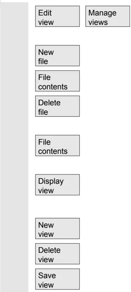
With the "Edit view" and "Manage views" softkeys you can open a window in which files and views can be
- created
- displayed and
- deleted.

E dit view Manage views
New file File contents Delete file
File contents
Display view
New view Delete view Save view
The "File contents" softkey takes you to another window in which the views of the previously selected file are displayed. With the "Display view" softkey you exit the dialog box and the previously selected view is displayed on the "System variable views" screen.
These softkeys also enable you to create views,
delete views and
save the currently displayed view under a selected name.
5 Parameters operating area 01/2008 5 5.8 Display system variables
5.8.3 Logging system variables
Function
When variables are used in synchronized actions, it may be necessary to evaluate and log the status of actions in the interpolation cycle. This is done by writing the values selected for a log definition to a log file of defined size in the specified cycle.
Recording of synchronized action variables can be limited to the event with identification number 1.
This event records variables in the IPO cycle or multiples thereof.
- A maximum of 6 variable contents can be recorded simultaneously in the log file.
- Size for memory depth: Values between 3 and 50 KB.
The HMI interprets the contents of the log file and displays them in graphic form.
Sequence of operations
The "System variable views" appears.
The "Variable log" softkey opens the screen with the heading "Log system variables".
The "Insert variable" softkey opens a dialog box in which the system variable to be recorded can be selected.
The "Insert user variable" softkey opens a dialog box in which the existing user variable can be selected.
The variable name in the higher-level window in the current recording list appears after confirmation with "OK".
If the list already contains 6 entries, the entry on which the cursor is positioned is overwritten.
Whenever you create a log, you must first initialize the logging function in the NC by pressing the "Initial. log" button.
You are informed when initialization is complete in the bottom left-hand corner of the display with the message "Logging initialized - You can now start".
\begin{tabular}{ll} System & The "System variable views" appears. \ variable & \ Variable & The "Variable log" softkey opens the screen with the heading "Log \ log & system variables". \ Insert & The "Insert variable" softkey opens a dialog box in which the system \ variable & variable to be recorded can be selected. \ Insert user & The "Insert user variable" softkey opens a dialog box in which the \ variable & existing user variable can be selected. \ OK & The variable name in the higher-level window in the current recording \ & list appears after confirmation with "OK". \ & If the list already contains 6 entries, the entry on which the cursor is \ & positioned is overwritten. \ Initial. & Whenever you create a log, you must first initialize the logging \ log & function in the NC by pressing the "Initial. log" button. \ & You are informed when initialization is complete in the bottom left- \ & hand corner of the display with the message "Logging initialized - You \ & can now start". \ \end{tabular}
5-248 © Siemens AG 2008 All rights reserved.

5
Parameters operating area
5.8 Display system variables
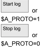
Start log or $A_PROTO=1 Stop log or $A_PROTO=0
You can start logging by pressing the "Start log" button or with the system variable $A_PROTO=1 in the part program.
It is stopped with the "Stop log" button or the system variable $A_PROTO=0.
After stopping, the log memory is automatically loaded to a file.
Manage log
The button "Manage log" calls up a dialog box in which you can
- Save a new log to a file or
- Reselect a log that is already saved.
Graphic log
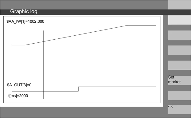
With the "Graphic log" button you call up a window in which the changeover time of the variables is displayed as a curve.
Measuring times are output along the horizontal axis and variable contents are output along the vertical axis. A graphic log window may contain several curves, the appropriate variable name is displayed at the top left of each curve.
Set marker
The "Graphic log" display provides you with a zoom function in which a section that you have already selected can be expanded to cover the entire display surface.
With the "Set marker" softkey a vertical cursor line appears, which is moved with the cursor left and cursor right keys.
The softkey text then changes from "Set marker" to "Set marker2" and from "Set marker2" to "Expand".
5 Parameters operating area 01/2008 5.8 Display system variables
Variable values marked by the cursor line are displayed on the left of the display. You do not need to normalize the display in any way, normalization values are calculated automatically. The characteristic is automatically normalized to values between minimum and maximum. Binary signals are represented in expanded form.
"Program" operating area
6.1 Program types 6-253 6.1.1 Part program 6-253 6.1.2 Subprogram 6-253 6.1.3 Workpiece 6-253 6.1.4 Cycles 6-253 6.1.5 Storing programs 6-253 6.1.6 Templates 6-254 6.2 Main screen program 6-256 6.3 Edit programs iin the standard ASCII Editor 6-258 6.3.1 Undo and redo in the standard ASCII editor 6-260 6.3.2 Additional optional editors 6-261 6.3.3 Selective program protection RO 6-261 6.4 Structured step sequence display (option) 6-263 6.5 Multi-channel step sequence programming (option) 6-267 6.5.1 Multi-channel workpiece program views 6-270 6.5.2 Activating timing 6-276 6.5.3 Activating simulation 6-277 6.6 Multiple editor (option) 6-281 6.6.1 Operator/display functions in the ASCII full views 6-281 6.6.2 Alignment of the channels/MPFs to be displayed 6-285 6.7 Free contour programming 6-287 6.7.1 Programming a contour 6-288 6.7.2 Undercuts for turning technology 6-293 6.7.3 Parameterizing contour elements 6-296 6.7.4 Graphically displaying the contour 6-298 6.7.5 Symmetrical contours with milling technology 6-299 6.7.6 Specifying contour elements in polar coordinates, closing the contour 6-302 6.7.7 Support for contour programming 6-307 6.7.8 Parameter description of the contour elements straight line/circle 6-308 6.7.9 Programming examples for freely programming a contour 6-309 6.7.10 Cycle support 6-313 6.8 Program simulation 6-314 6.8.1 Using the simulation function 6-316 6.8.2 Simulation settings 6-325 6.8.3 Setting downtimes 6-331 6.8.4 Display and colors 6-332 6.8.5 Section-by-section simulation 6-333 6.8.6 Quick display in the simulation for mold making 6-334 6.8.7 Simulation with external network drive 6-336 6.8.8 Simulation for orientable toolholder 6-337 6.9 Managing programs 6-337
©Siemens AG 2008 All rights reserved.
6.9.1 New workpiece/part program ………………………………………… 6-339
6.9.2 Create programs/data in a workpiece directory …………………… 6-341
6.9.3 Saving setup data …………………………………………………… 6-342
6.9.4 Selecting a program to be executed ……………………………… 6-343
6.9.5 Loading/unloading a program ……………………………………… 6-346
6.9.6 Manage programs …………………………………………………… 6-347
6.9.7 Copying/inserting ………………………………………………… 6-348
6.9.8 Deleting …………………………………………………………… 6-351
6.9.9 Renaming …………………………………………………………… 6-352
6.9.10 Enabling …………………………………………………………… 6-353
6.9.11 Protocol …………………………………………………………… 6-354
6.10 Accessing an external network drive/computer …………………… 6-355
6
"Program" operating area 6.1 Program types
6.1 Program types
6.1.1 Part program
A part program consists of a sequence of instructions to the NC control. In its entirety, this sequence affects the production of a specific workpiece or a particular machining process on a given blank.
6.1.2 Subprogram
A subprogram is a sequence of instructions in a part program which can be called repeatedly with different defining parameters. Cycles are a type of subprogram.
6.1.3 Workpiece
- A workpiece is a part to be produced or machined by the machine tool or from the HMI perspective is to be produced or machined.In the HMI, a workpiece is a directory in which programs and other data for machining a particular workpiece are stored.
6.1.4 Cycles
Cycles are subprograms for the execution of a recurring machining process on the workpiece.
6.1.5 Storing programs
Programs can be saved in the NC memory or on hard disk. The currently available memory space is displayed in the user response line. Cycles can also be stored in the NC Flash File System.

6 "Program" operating area 6.1 Program types 01/2008 6
6.1.6 Templates
Templates are objects that can be used for creating new workpieces, part programs, subprograms, job lists, work offsets, etc. and can be edited and customized to suit the task at hand. With HMI Advanced, templates for job lists are stored in the file system by default. Specific user templates must first be created in template directories. This allows you to access them when creating new objects. Templates can be designed in different languages and named to allow easy language-specific access to them. If you create a template with a wildcard in the name, the current workpiece name will be inserted into the name when the template is activated.
There is no difference between creating templates and creating workpieces, part programs, subprograms, job lists, work offsets, etc. You can use the administration functions and naming conventions to enter objects you want to use as templates in the template directory. Templates can be created from the Services operating area directly in the required directories. Existing templates are offered for selection when you create new objects.
Naming conventions for templates
TEMPL If this string is assigned as part of the template name, it is replaced by the workpiece name when the template is activated. The template is not copied if the name exceeds 24 characters after replacement.
_XX If the template name terminates in _XX (XX stands for the language code, e.g., _GR for German), only the objects are offered from the template directory where the current language matches the language code in the template name. Templates for different languages can therefore be stored together in the template directory.
1_1 If the template name starts with 1_1, the template is proposed for standard configuration.
M_N If the template name starts with M_N, the template is proposed for M:N system configurations (netnames.ini is configured). 1_1 or M_N can be combined with _XX.
6 01/2008 "Program" operating area 6.1 Program types 6
Additional information
Language-specific templates are given priority over non-language-specific templates with the same core name component. Therefore, you can create a template which can be used for all languages for which no language-specific variants are available.
Directories for templates
The Services operating area contains the following subdirectories under Templates: Users Empty when shipped Vendor Empty when shipped Siemens Standard job lists provided when shipped
Templates Empty when shipped
If the Templates subdirectory for this data type is not empty when creating a new data type, you can enter "No template" to access the templates in the user, manufacturer and Siemens directories.
User, manufacturer and Siemens templates are available for individual file types under: Commissioning \rightarrow HMI \rightarrow System settings \rightarrow Templates The activation differs according to: – Job lists – Initialization programs – Part programs/subprograms –
In the Templates directory, you can store:
- Individual templates for various data types and
- Complete workpieces as templates in a subdirectory. The full workpiece templates are offered for selection when data type WPD is newly created. If selected, all components belonging to the template are copied to the new workpiece in accordance with the above naming conventions. With other data types only the selected template is used.
Create templates
In the Services operating area select the directory for which you are authorized. Templates/Users /Manufacturer /Siemens /Templates
Define the name, data type and - if required - template. Confirm with OK. Use the editor to process the created template.
6 "Program" operating area 01/2008 6 6.2 Main screen program
Save templates You can use the administration functions to copy and paste template objects to the directories and use the above mentioned naming conventions to rename the templates e.g., for specific languages or workpiece names.
You can save existing templates under Services "Data out" or read saved templates back in with "Data in".
6.2 Main screen program
The program's main screen contains a complete overview of all workpiece and program directories.
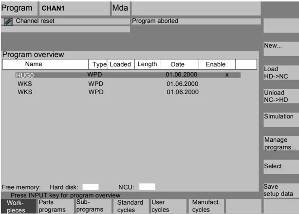
Horizontal softkeys
Part programs An overview of all part programs (main programs) stored in the selected directory is displayed.
Sub-programs An overview of all subprograms stored in the selected directory is displayed. Subprograms are processed in the same way as described for "Process main programs".
6-256 © Siemens AG 2008 All rights reserved.
6 01/2008 "Program" operating area 6.2 Main screen program 6
Standard cycles Select the "Standard cycles" softkey to display a list of the cycles that Siemens has added. See softkey definitions.
User cycles Select the "User cycles" softkey to display a list of the user cycles that you have added.
Manufact. cycles Select the "Manufacturer cycles" softkey to display a list of the cycles that have been integrated by the manufacturer.
Log After pressing the "ETC" key and the "Log" softkey, you can display the log of error messages for errors which occurred during "Copy", "Rename", "Load", etc.
Softkey definitions
If external network drives are configured for the control, the softkeys for these drives replace the "Standard cycles", "User cycles" and "Manufacturer cycles" softkeys. If you have configured four softkeys, the fourth one is displayed in the More bar when you press the "ETC" key. If network drives are configured, the "Standard cycles", "User cycles" and "Manufacturer cycles" softkeys also appear in the More bar after pressing the "ETC" key.
V ertical softkeys
New... Creates a new file for a workpiece/part program. If activated templates exist for the created data type, they are proposed. If they are accepted, the copy of the template becomes the created object.
Load HD->NC The highlighted program (or programs) is (are) loaded from the hard disk to the NC memory.
Unload NC->HD The highlighted program is unloaded from the NC memory to the hard disk.
Simulation With the function "Simulation" you can display axis movements graphically and simulate the results of machining on the screen.
Manage programs... With the "Manage programs" softkey you can manage the functions "New", "Copy", "Insert", "Delete", "Rename" and "Enable".
6 "Program" operating area 01/2008 6.3 Edit programs iin the standard ASCII Editor
Selection The name of the selected workpiece is displayed in the top of screen in the "Program name" field. The program is also loaded and selected for processing.
<< When you branch to a workpiece, the "<<" softkey automatically appears to allow you to return to the main menu.
6.3 Edit programs iin the standard ASCII Editor
Function
The default editor for creating and editing part programs or other text files is the standard ASCII editor. This allows users to edit part programs using individual instructions: G codes, keywords, etc.
The version with two windows displaying two sets of program instructions side-by-side is referred to as the "Dual ASCII editor" (dual editor).
- The standard ASCII editor displays the characters that can be entered via the keys on the operator panel.
- A part program opened by the editor cannot be simultaneously started in the NC (enable is canceled); an alarm (14011) is indicated in this case. If the control is switched off while the editor is open, the enable might have to be set manually.
- When you exit the editor after editing cycles in the NC and if these cycles are also stored in the Flash File System, then an activity symbol (fan symbol) is displayed while the data is being copied into the Flash File System.
See also: → Subsection 6.1.5 Storing programs → Chapter 2 General operating sequences
6.3 Edit programs in the standard ASCII Editor
Dual ASCII editor
If you are positioned on a subprogram call in the ASCII editor, this program is loaded to the second editor when you press the "View subprogram" softkey.
This function is only available in the ASCII editor.
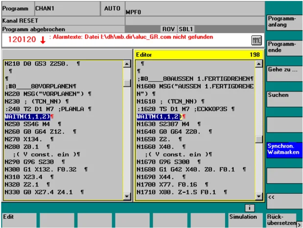
Synchronized view in the dual ASCII editor
You can view instruction groups in the ASCII editor. Position the cursor on a WAIT marker instruction in one of the two ASCII editors.
Press the "Synchron. WAIT markers" softkey. This string is sought in the second editor and displayed at the same height in the window as the cursor in the first editor. The focus remains in the first editor.
If no WAIT marker instruction is found together with its brackets, the next WAIT marker instruction is displayed in the adjacent window regardless of the brackets.
6 "Program" operating area 01/2008 6.3 Edit programs iin the standard ASCII Editor 6
6.3.1 Undo and redo in the standard ASCII editor
Function
Edit When editing a part program or a text file, you can undo complete blocks in the editor:
- Press "Ctrl" and "Z" for "Undo" (reset)
- Press "Ctrl" and "Y" for "Redo" (reactivate)
Once you undo a series of blocks, you can redo the same number of blocks. Both functions only apply to programs that are not loaded.
Sequence of operations
"Ctrl" + "Z" Press the key combination "Ctrl" + "Z". All changes in the entire block are undone. Repeat the key combination to undo the previous change. The "CR" symbol at the end of the block is also considered. This procedure can be repeated until the last change or the set number of changes has been reached.
"Ctrl" + "Y" Press the key combination "Ctrl" + "Y". The last changes undone in the editor are redone. This procedure can be repeated until the last change is redone or the set number of maximum changes has been reached.
The default number is 10 steps; this setting can be changed. Setting the number to zero deactivates the function.
References Commissioning Manual HMI-Advanced (IM4)
6 01/2008 "Program" operating area
6.3 Edit programs iin the standard ASCII Editor
6.3.2 Additional optional editors
Step editor display (option) As an option, the single step sequence display can be used with extended functions. These extended functions allow you to process technology-oriented program steps which are stored and displayed with special icons in the editor for each step type to enable easier recognition. The steps must be defined in the SEDITOR.INI file:
- Groups of individual instructions: G codes, keywords, etc.
- Synchronization instructions (e.g. WAITM)
- Cycles
- Contour definitions
Advantages:
- Improved readability of programs
- Operations based on steps (copy, insert, delete etc.)
- Recompilation from step to DIN code, contour definition and cycle display available
- Step sequence displays form the basis for the multi-channel step sequence programming
See Section 6.7 Structured display in the step editor (option)
Multi-channel step sequence programming (option) Multi-channel step sequence programming is available as an option and offers the following features:
- Simultaneous display of several programs for a workpiece in multiple channels
- Optional fixed step lengths or time proportional display of step lengths in the channels
- Display of processing duration for steps and waiting time at synchronization points
See Section 6.8 Multi-channel step sequence programming (option)
6.3.3 Selective program protection RO
Function
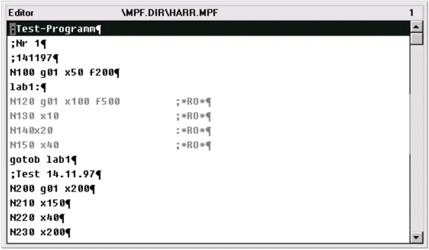
In programs written with program templates or when using the programming support functions, certain machine-specific code lines may be protected against changes.
A read-only identifier (";RO") is tagged onto the code program blocks as a comment.
6 "Program" operating area
6.3 Edit programs iin the standard ASCII Editor
The user can always identify protected program sections by the "Read Only" identifier (";RO"). Any attempt to change a program part protected by the read-only identifier is denied with the message "Block cannot be written".
Example The ASCII editor recognizes these blocks, hides them or displays them in the read-only text color (gray), and prevents changes to these blocks.
Reserved character strings Reserved character strings occur in part program code lines which are generated by calling cycles and programming contour definitions. They can be viewed by setting "Display hidden lines" in the editor.
The following character strings must not be used in part program lines that are directly input: ;# ;#END ;NCG ;RO ;HD
Additional information When creating a program template, remember to position the "Read Only" identifier directly at the end of the block.
6 01/2008 "Program" operating area
6.4 Structured step sequence display (option)
Function
You can either edit a part program in the ASCII editor (standard display) or in step sequence display ("Sequence" softkey).
Configuring the SEDITOR.INI file enables NC programs to be displayed in a structured manner without changing the program. In addition, the "SEFORM()" instruction can be inserted for a structured step display.
Advantages:
The step view improves the readability of the NC program. Step sequence display has the following advantages:
- Quicker sequence detection
- Quicker navigation
- Easier sequence editing (block functions at step level: e.g., modifying the sequence)
- Single keystroke (Recompile or Input) to access the standard ASCII editor environment (ASCII or dialog with support functions such as cycle screens, contour calculator).
If you have created your own user cycles, which you use regularly in several programs and want to display clear steps, please contact your machine supplier so that a user-specific SEDITOR.INI can be placed in the user area for you.
Structure
Specific keywords stored in the configuration file are searched for in the ASCII program of the loaded program. These are then assigned to the primary level or secondary level to create a structure for the step sequence display. As a result, a structured display can be achieved in so-called step sequences without changing the ASCII program. The special display of control structures such as IF, THEN, ELSE, GOTO, CASE, FOR, WHILE, etc., has not been considered here. Using the SEFORM instruction it is possible to achieve additional structures in the program, if required. Pressing the keys CTRL + I will insert a predefined SEFORM instruction in the SEDITOR.INI.

The configuration file stores the following information:
- Which single or multi line sequence is recognized as a step (e.g., cycle call, contour element, WAITM call)
- Which step identifier and which symbol is displayed instead of the recognized sequence
- To which level (0-Primary level/1-Secondary level) a symbol and to which step identifier the recognized sequence should be assigned.