5 01/2008
Parameters operating area
5.3 Tool management
Sequence of operations
Prerequisite I. Filter selection
Select the tool management
"Filter lists" softkey
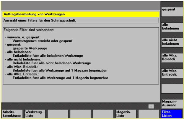
The screen provides up to 6 filters for selection by softkey, depending on the configuration in paramtm.ini.
Vertical softkeys
Filter 1-6 The softkey label "Filter 1- 6" is an example of how a label can be configured to represent the 6 filters that are permitted. Pressing the softkey starts determining the tools that match the criteria in the NC and jumps to a 2nd screen that displays the hit list. The filter produces a snapshot of the data. This data is not updated later.
Magazine selection You can use the filter definition to specify whether the filter always applies to the whole TOA or is restricted only to single magazines. You can use the "Magazine selection" softkey to select a particular magazine or "All magazines" for a restrictable filter. When you switch from a magazine list to the filter lists and no current filter or batch processing is active in the TOA (you access the first screen "Filter selection"), the current magazine in the magazine list is taken as the preset value for restrictable filters. If the situation is the same when coming from the tool list, the preset value is "All magazines".
5 Parameters operating area 5.3 Tool management
II. Hit list in the "Loading list" and "Standard list" screens
The "Hit list" screen has one of 2 configuration-dependent variants:
- Loading list with the functions "Load" and "Reactivate"
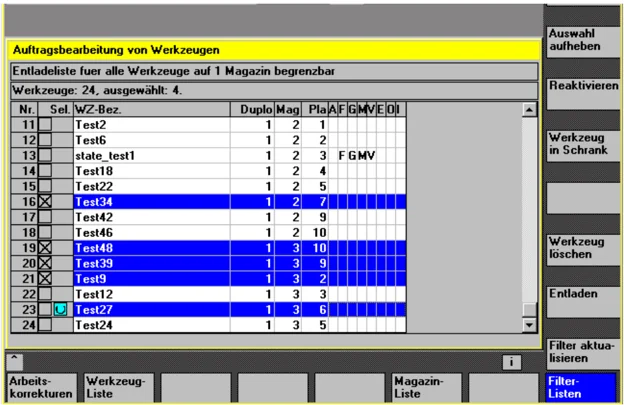
- Standard list with the functions "Reactivate", "Unload", "Delete", "In cabinet".
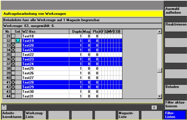
When filtering has started in screen 1 "Filter selection", the tools found in screen 2 "Hit list" are displayed in a list with one line per tool. The data are a snapshot created at the time of filtering; it is not updated later when the data in the NC change.
Selection of tools
No tool is selected for batch processing at the outset. By positioning the cursor and pressing the Select key, you can toggle the tool selection for batch processing. To change the tool selection for batch processing, you can use the "Select all" and "Deselect" softkeys.
Selected tools are represented in color and also indicated by a symbol in the 2nd column of the hit list on the display screen.
In the standard setting, a tool selected for batch processing is displayed with a checkbox that has been selected (☑ and ☐). The color for "Cursor" and for "Selected for batch processing" is identical and corresponds to the general selection display. When selection of the tools is completed, press the softkey to start the batch function.
5 01/2008 Parameters operating area 5.3 Tool management 5
Start batch function
"Load"
Vertical softkeys
Select all All tools in the hit list are selected for batch processing.
Cancel selection The selection for batch processing is canceled for all tools in the hit list.
Load "Loading" is initiated as a batch command for the selected tools. You are prompted to enter the destination magazine and the load point in a dialog box.
Reactivate "Reactivate" is initiated as a batch command for the selected tools. When reactivating a tool, the monitoring actual values and the wear are reset. You can use the INI file (entry n_ ReactivatePositioningMode) to specify (for each filter) whether reactivation is to be carried out "always", "never", or "on request" with magazine positioning. Depending on the setting, the dialog box prompts for positioning and the load point as appropriate to the setting.
5 Parameters operating area
5.3 Tool management
"Unload"
Reactivate "Delete" is initiated as a batch command for the selected tools. Loaded tools are unloaded prior to deletion. You are prompted to specify the unloading point in a dialog box.
Unload "Unload" is initiated as a batch command for the selected tools. The tools are not deleted. You are prompted to specify the unloading point in a dialog box.
Relocate "Relocation" is initiated as a batch command for the selected tools. A dialog box prompts you to enter the destination magazine where the tools are to be relocated. This magazine is the destination for all tools in this batch processing operation.
In the cabinet The "In the cabinet" batch command is initiated for the selected tools. This function is similar to the "Delete" function; in addition, the tool data are saved in the tool cabinet database. Loaded tools are unloaded before being saved and deleted. In this case, the unloading point is queried interactively.
Update filter The current filter and its magazine settings are used again and a new hit list produced. The tool selection for batch processing is canceled completely.
Recall "^" The current number of hits is discarded and the 1st screen, "Filter selection", is displayed.
If batch processing has been started and the necessary entries have been made, the display switches to the 3rd screen, "Batch execution".
5 01/2008 Parameters operating area 5.3 Tool management 5
Batch execution
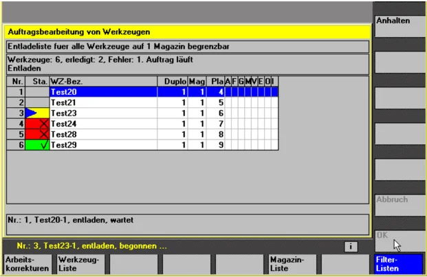
The screen shows the information relating to the batch execution as a whole and with respect to the individual tools. The user may halt, continue or cancel batch processing and monitor the results during and after batch processing.
Each tool is represented by a separate line in the list. The status of the tool is represented by the configured symbol in the 2nd column.
The following states are displayed by default:
- "Waiting to be machined": Gray field,
- "Current tool in batch processing": yellow/blue arrow,
- "Completed without errors": Green field with check mark,
- "Completed with error(s)": Red field with "X",
The status of the tool on which the cursor is placed is displayed in the form of a text, for example, any errors, load destination.
The state of the current tool in batch processing is displayed in the message line.
If the user does not move the cursor for a few seconds, the cursor is automatically placed on the current tool for batch processing when the next processing step has been completed.
5 Parameters operating area 01/2008 5
5.3 Tool management
V ertical softkeys
Stop Batch processing is halted. Processing of the active element up to this point is either completed or canceled depending on the status and batch type. This softkey can only be used while batch processing is in progress.
Continue Any batch processing operation that has been halted is continued. This softkey can only be used while batch processing is halted.
Abort Any batch processing operation that is halted is canceled. Non-completed jobs are discarded and display returns to the "Filter selection" screen. This softkey can only be used while batch processing is halted.
OK All information relating to completed, detailed batch operations is discarded and the display returns to the "Filter selection" screen: This softkey can only be used when all detailed batch operations have been completed, irrespective of whether errors occurred or not.
Batch processing continues running in the background when you switch from your operator interface to other tool management screens or to other operating areas.
5.4 R parameters (calculation parameters)
Function
Parameters are read and written by programs. In this operating area, parameters can be edited manually.
Edit/delete/find R parameters
The number of channel-specific R parameters is defined in a machine data element. Range: R0 – R999 (dependent on machine data). There are no gaps in the numbering within the range.
Sequence of operations
R parameters The "Channel-specific R parameters" window appears. The channel-specific parameters are displayed. The vertical softkey bar changes.
PAGE UP PAGE DOWN You can page up and down using the "Page" keys.
Edit parameters:
Position the cursor bar on the appropriate input field and enter the new values.
Delete area
Delete parameters :
Displays a screen in which you can specify the R parameter range Rx to Ry to be deleted.
Delete all The entire R parameter range is deleted, i.e., all values are set to "0".
Abort Inputs are discarded.
OK Deletes the entered R parameter range.
Find
Find parameters:
An input window for a parameter number appears when you press the "Find" softkey. Enter the R parameter number you wish to find via the numeric keypad.
INPUT When you press the "Input" key, the cursor is automatically positioned on this parameter if it exists.
5 Parameters operating area 01/2008 5 5.5 Setting data
Additional information
Input and deletion of parameters can be disabled via the keylock switch.
5.5 Setting data
5.5.1 Working area limitation
Function
The "Working area limitation" function can be used to limit the range within which a tool can traverse in all channel axes. These commands allow you to set up protection zones in the working area which are out of bounds for tool movements.
Setting data
Working area limitat.

Sequence of operations
Press the "Setting data" softkey. The vertical softkey bar changes.
Press the "Working area limitation" softkey. The "Working area limitation" window opens.
Edit the working area limitation: Position the cursor on the desired field. Enter the new values on the numeric keypad. The upper or lower limit of the protection zone changes according to your input.

Activate the appropriate working area limitation with the <SELECT> key.
In "MDA" and "Automatic" modes, the working area limitation is not activated according to setting data within the current NC program until a "WALIMON" command is set.
Additional information
The "Working area limitation" function can be disabled by means of the keylock switch.

5.5.2 JOG data
Function
The feedrates must be specified in the unit determined by the G function.
G function
- G94 Feedrate in mm (inch)/min
- G95 Revolitional feedrate in mm (inch)/rev
JOG feedrate
Feedrate value in the JOG mode
Continuous JOG
- JOG mode: The axis moves as long as the key is pressed.
- Continuous mode: The axis begins to move when the key is pressed once and continues until:
- The key is pressed again.
- NC Stop.
- Reset.
- Software/hardware limit switch.
Variable increment
Increment value for JOG variable increment
The following data are displayed only if a spindle is configured:
JOG spindle speed
Spindle speed in JOG mode
Spindle
JOG data for the master spindle:
- Spindle no.: Name of leading spindle
- Direction of rotation: Direction of rotation of leading spindle
- Spindle speed: Speed of the master spindle in JOG mode
Sequence of operations
Press the "Setting data" softkey.
The vertical softkey bar changes.
Press the "JOG data" softkey.
The "JOG data" window is opened.
Edit spindle data
Position the cursor bar on the appropriate input field and enter a new value.
or:
Select a new value using the <SELECT> key.

5 Parameters operating area
5.5 Setting data
Additional information
The limit values for the maximum and minimum permissible values are defined in the machine data.
5.5.3 Spindle data
Function
Max./min. The value entered for the spindle speed in the fields max./min. must be within the limit values defined in the machine data.
Programmed Programmable upper speed limit (G96) for constant cutting speed.
Sequence of operations
Press the "Setting data" softkey. The vertical softkey bar changes.
Press the "Spindle data" softkey. The "Spindle data limitation" window opens.
Edit spindle data Position the cursor bar on the appropriate input field and enter a new value. or: Select a new value using the <SELECT> key.

Additional information
- The limit values for the maximum and minimum permissible values are defined in the machine data.
- The "Spindle data" function is displayed only if a spindle is configured.
5
Parameters operating area 5.5 Setting data
5.5.4 Dry run feedrate for dry run operation DRY
Function
The feedrate entered here is used in the active program instead of the programmed feedrate when the function "Dry run feedrate" (program control) is selected in "Automatic" mode.
Sequence of operations
Setting data
Press the "Setting data" softkey. The vertical softkey bar changes.
Feedrate DRY
Press the "Feedrate DRY" softkey. The "Dry run feedrate" window is opened.
Edit the dry run feedrate: Enter a new value.

5 Parameters operating area
5.5 Setting data
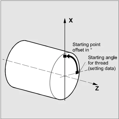
5.5.5 Starting angle for thread cutting
Function
For thread cutting, a starting position for the master spindle is displayed as the starting angle. A multiple thread can be cut by changing the angle when the thread cutting operation is repeated.

Sequence of operations
Press the "Setting data" softkey. The vertical softkey bar changes.
Edit starting angle: Press the "Starting angle" softkey. The "Starting angle for thread" window opens.
Enter a new value.
Setting data
Starting angle

5
Parameters operating area 5.5 Setting data
5.5.6 Miscellaneous setting data
Function
All the setting data in the control are displayed in tabular form sorted according to general (i.e., NCK-specific), channel-specific and axis-specific setting data. The table contains both the setting data on the vertical softkeys such as working area limitation, Jog data etc., as well as special setting data such as software cam, oscillation, compensation, etc.
Sequence of operations
Setting data
Press the "Setting data" softkey. The vertical softkey bar changes.
Misc.
Display setting data: Press the "Misc." softkey. The horizontal and vertical softkey bars change.
General SD
Select the type:
- The "General setting data ($SN_)" window appears.
- The "Channel-specific setting data ($SC_)" window appears.
- The "Axis-specific setting data ($SA_)" window appears.
Channel- specific SD
Axis- specific SD
The current setting data of the corresponding type $SN_, $SC_ or $SA_ are displayed.
PAGE UP PAGE DOWN
Use the PageUp / PageDown keys to browse forward / backward.
Find
Find setting data: Enter the setting data you wish to find in the "Find" window (initial ID is sufficient).
Find next
If several setting data have the same initial identifier, you can display other setting data by selecting the "Find next" softkey.
Edit setting data: Position the cursor bar on the appropriate input field and enter a new value.

5 Parameters operating area 5.5 Setting data
Additional information
Data can be edited or not depending on the active access protection level.
5.5.7 Protection zones
Function
The "Protection zones" function allows you to protect various elements on the machine, your equipment or the machined workpiece against incorrect axis motions. You can view up to 10 programmed protection zones in levels G17, G18 and G19.
For further information about protection zones, please refer to /PGA/, Programming Guide Advanced.
Sequence of operations
Press the "Setting data" softkey. The vertical softkey bar changes.
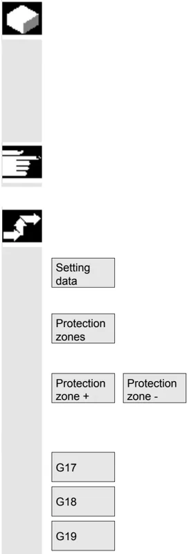
Press the "Protection zones" softkey. The "Working area limitations and protection zones" window opens. The vertical softkey bar changes again.
Press the "Protection zone +" or "Protection zone -" softkey. Up to 10 protection zones are displayed in succession.
Select the plane in which the relevant protection zone is located:
- Plane G17 (X,Y; Infeed direction Z)
- Plane G18 (Z,X; Infeed direction Y)
- Plane G19 (Y,Z; Infeed direction X)
5.5.8 Electronic gear
Function
The "electronic gear" function allows you to move a drive axis as a following axis in synchronism with up to five leading axes. The electronic gear is encoded via the following axis and has several lead axes, each of which applies a gear ratio. The ratio to the drive axis has a linear response and is defined as a coupling factor, numerator to denominator. A gear group is defined and activated during part program execution.
References
For further information, please see /PGA/, Programming Guide Advanced.
Sequence of operations
Press the "Setting data" softkey. The vertical softkey bar changes.
Press the "Further >>>" softkey. Two further softkeys appear, "Gearbox link" and "<<", for changing to the first softkey bar.
The vertical softkey bar changes to the "Electronic gear"
Following axis
Leading axes
- 1 ☐
- 2 ☐
- 3 ☐
- 4 ☐
- 5 ☐
Coupling factor Counter instructions Denominator
Synchronization position Following axis Leading axis
: Displays the position at which the teeth of the : electronically simulated gear engage : : :
You can use the softkeys "Following axis + +" and "Following axis - -" to advance the following axis in both directions through the configured gear stages. The motion component of the following axis is derived from the coupling factors of the individual leading axes.

5 Parameters operating area 01/2008
5.6 Zero/work offset
5.6.1 Function
Machine/tool zero The actual values are referred to the machine zero after a reference point approach. The machining program of the workpiece refers to the workpiece zero. Machine zero and workpiece zero need not be identical. Depending on the type of workpiece and the way it is clamped, the distance between the machine zero and workpiece zero can vary. In part program processing this is compensated for by the work offset.
Work offset on a milling machine
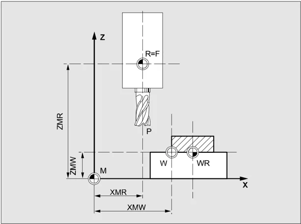
P Tool setting point W Workpiece zero F Slide reference point XMR, ZMR Reference point coordinates XMW, ZMW Zero/work offset M Machine zero R Machine reference point WR Workpiece reference point
Effective WO The work offset effective in an axis $P_ACTFRAME=.. results from the sum of the following zero point offsets:
5 01/2008
Parameters operating area 5.6 Zero/work offset
Settable WO You can activate a settable zero point offset in the part program you have called with G54 to G57 and other G functions or with $P_IFRAME=.. Basic work offset (basic frame): displayed like a settable WO.
Programmable WO You can use the programmable zero point offset $P_PFRAME=.. to program an additional zero point offset for geometry and special axes in the part program you have called. The values of the programmed work offsets are deleted with end of program or reset.
External WO In addition to all the offsets which define the position of the workpiece zero, an external work offset can be overlaid by means of the handwheel (DRF offset) or from the PLC.
DRF offset Differential Resolver Function: NC function which generates an incremental work offset in Automatic mode in conjunction with an electronic handwheel.
Frame Frame is the conventional term for a geometrical expression that describes an arithmetic rule, such as translation or rotation. Frames are used to describe the position of a destination coordinate system by specifying coordinates or angles starting from the current workpiece coordinate system. Possible frames:
- Basis frame
- Settable frames (G54...G599)
- Programmable frames
References: /PG/, Programming Guide Advanced
Frame components Frame components A frame can consist of the following arithmetic rules:
- Work offset, TRANS, ATRANS
- Rotation, ROT, AROT
- Scale, SCALE, ASCALE
- Mirroring, MIRROR, AMIRROR
In the part program, all work offsets can be deselected non-modally with G53.
Graphical display of work offset See Subsection 4.2.3 Toggle between machine/workpiece coordinate system (MCS/WCS)

5 Parameters operating area
5.6 Zero/work offset
5.6.2 Edit the settable work offset (G54 ...)
Function
-
$P_UIFR[]
This identifier can be used to edit a settable work offset in the program. -
Coarse offset
The value of the coarse offset is defined for the relevant axis. -
Fine offset
MD 9451: WRITE_ZOA_FINE_LIMIT specifies the data limits (absolute) for the fine work offset. The fine offset is displayed in the "Settable work offset" display.
Activation of WO via MD 18600: MM_FRAME_FINE_TRANS.
5.6.3 Global zero offset/frame
Function
In addition to the settable, programmable and external work offsets, up to eight global work offsets/frames (basic WO) can be defined. This allows offsets, scales and mirrors to be defined simultaneously for all channel and machine axes.
The global work offsets (NCU global frames) apply uniformly to all channels. They can be read and written from all channels. The activation is performed in the relevant channel.
- Basic TO (total basic frame)
In addition, eight channel-specific basic work offsets can be defined in each channel. The global and channel-specific frames are combined to produce a total basic frame (basic WO).
Machine manufacturer
Recommendation:
Use the 3rd basic offset onwards for your own applications. The 1st and 2nd basic offsets are reserved for setting the actual value and the external work offset.
5 01/2008 Parameters operating area 5.6 Zero/work offset 5
With global frames there is no geometrical relationship between the axes. It is therefore not possible to perform rotations or program geometry axis identifiers.
The settable work offset and the basic work offset are represented in one table. You can edit the values in this table. You can switch between the values of the individual axes.
For all work offsets, you can display either the defined offsets (coarse and fine) or the specified rotations, scales and mirrors for each value.
References /FB/ K2: Axis Types, Coordinate Systems, Frames
Rotation The value of the rotation around the respective geometry axis (e.g. X, Y, Z) can be entered. Rotation can only be programmed around geometry axes.
Scale The scale factor can be defined for the respective axis.
Mirroring Mirroring of the relevant axis around the coordinate zero can be activated and deactivated.
Display and edit work offsets
Press the "Work offset" softkey. The vertical softkey bar changes.
The display switches to the defined work offsets of the next axis.
The display switches to the defined work offsets of the previous axis.
You can use these softkeys to change the display mode of the currently displayed work offsets. The following takes place:
- Either the absolute offsets (coarse and fine) with reference to the coordinate axes
- Or a list of individual values, split into components for rotation, scale and mirroring.
You can select and, if necessary, edit the individual values of the work offsets in both display modes.
SINUMERIK 840Di sl/840D sl/840D Operating Manual HMI-Advanced (BAD) - 01/2008 Edition 5-233

5 Parameters operating area
5.6 Zero/work offset
Basic WO All defined basic work offsets (global and channel-specific) are displayed in a table. The display mode can be changed by softkey (see above). You can edit the values directly in the table. Rotations are not possible with global frames, since no geometrical relationship exists between the axes in this case.
Settable WO All defined settable work offsets are displayed in a table and can be edited if necessary (select and edit).
Additional information
- Changes to the work offsets are updated immediately on input. The entries no longer have to be confirmed separately.
- If not all work offsets are displayed in the tables, you can scroll through the table with the corresponding keys.
Active WO + offset Press the "Active WO + offset" horizontal softkey. The vertical softkey bar changes.
Axes + Displays the active work offset of the next axis.
Axes - Displays the active work offset of the previous axis.
Offsets Rotation scl., mirr. You can use these softkeys to change the display mode of the currently displayed work offsets.
Change active WO A table of currently active work offsets and the offsets of the selected axis are displayed. You can select and, if necessary, edit the individual values in the table. The following values are displayed:
- Global basic WO; Coarse and fine (if defined)
- Channel-specific basic WO; Coarse and fine (if defined)
- Settable WO; Coarse and fine (G57)
- Programmable WO; G58 (TRANS), G59 (ATRANS)
- T number and D number of active tool
- G17 (geometry, wear, base).

5
Parameters operating area 5.6 Zero/work offset
5.6.4 Displaying an active settable work offset
Function
The active settable work offsets (selected from part program or MDA) can be displayed.
Sequence of operations
Press the "Work offset" and "Go to ..." softkeys. The vertical softkey bar changes.
The "Active settable WO" window opens. You can edit these values if necessary.
References
/PGA/, Programming Guide Advanced
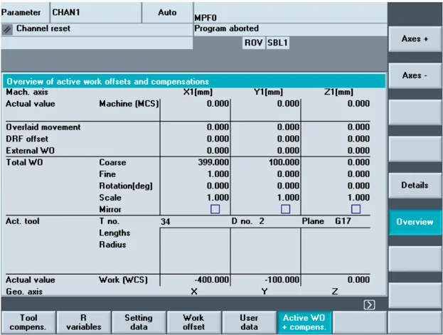
An overview shows all values of the active work offset and offsets (no changes possible) including a selection of tool data (T number, D number, etc.). The basic work offset and the settable work offset are displayed as the sum.

5 Parameters operating area 01/2008
5.6 Zero/work offset
The following values are displayed:
- Actual value of MCS and settable zero system
- Overlaid movements
- DRF offsets
- Zero offsets external
- Sum of the work offsets; calculated from the basic, settable and programmable work offsets (corresponds to the "Editing the active..." table)
- Data of the active tool (T number, D number with reference to the plane G17, lengths, radius)
- WCS actual value.
Additional information
The active work offset must be changed only when the NC program is stopped. Changes are updated immediately. The work offset values in the display are updated cyclically.
5.6.5 Displaying an active programmable work offset
Function
The active, selected programmable work offsets (from part program or MDI) can be displayed.
Values cannot be edited in this display.
Sequence of operations

Press the "Work offset" and "Go to ..." softkeys.
The vertical softkey bar changes.

The "Active progr. WO" window opens.
5 01/2008 Parameters operating area 5.6 Zero/work offset 5
5.6.6 Displaying an active external work offset
Function
The active, external work offsets can be displayed. Values cannot be edited in this display.
Sequence of operations
Press the "Work offset" and "Go to ..." softkeys. The vertical softkey bar changes.
The "External WO" window is opened.
5.6.7 Display the sum of the active work offsets
Function
The sum of the active work offsets from the part program can be displayed. Values cannot be edited in this display.
Sequence of operations
Press the "Work offset" and "Go to ..." softkeys. The vertical softkey bar changes.
The "Sum of WO" window is opened. The sum of work offsets is calculated in the following way: Sum WO = active settable WO + active programmable WO
The values can be edited only in the "Settable work offsets" menu. (see Section "Settable work offsets" menu)
SINUMERIK 840Di sl/840D sl/840D Operating Manual HMI-Advanced (BAD) - 01/2008 Edition 5-237

5 Parameters operating area
5.6 Zero/work offset
5.6.8 Activate active work offset and basic frame immediately
Function
Machine data MD $MM_ACTIVATE_SEL_USER_DATA can be set to ensure that the work offset and basic frame are made immediately effective when the part program is in the "Reset" state. This also occurs if the part program was first switched to JOG status. If the channel is in the "Reset" state, active work offset and basic frame are not activated until the part program is continued.
Additional information
When the function is used in the Reset state, MD $MC_RESET_MODE_MASK must be set such that the settable work offset or basic frame is not reset when the program switches to Reset.
Machine manufacturer
see the machine manufacturer's information.
/FB/ K2: Axes, coordinate systems, frames
Danger
The offset is applied the next time the part program is started.
5.6.9 Actual value display: Settable zero system, SZS
Function
You can make a setting in the MD to define whether
- The position of the workpiece coordinate system, WCS (= programmed position, corresponds to default setting) or
- The holding position of the active tool relative to the workpiece zero (settable zero system = SZS) must be shown in the actual-value display.
References
Commissioning Manual HMI-Advanced (IM4), Chapter Zero/work offset


5.7 Define user data
5.7.1 Define variables (GUD, PUD, LUD)
Function
User data (UD) can be defined by means of a variety of variables:
- GUD - global variables which are valid in all programs.
- LUD - local variables which are valid only in the program or subprogram in which they have been defined.
- PUD – global program variables.
Local variables (LUD) defined in the main program are turned into global program variables (PUD) by a setting in a machine data. PUD variables are valid on all subprogram levels, where they can also be written and read.
The user data (GUD) can be defined for HMI in the Services operating area (in the Definitions directory); reinitialization is not necessary. The following applies:
- Definition files that are on the hard disk are not active.
- Files can be transferred to NC and activated using the "Activate" softkey.
The user memory must be configured to a large enough size before the GUD definition file is loaded to the control. All relevant machine data have GUD as a component of their name.
The display of global user data (GUD) can be locked by means of the keylock switch or a password.
For more information on how to protect global user data in the part program, please refer to
/PGA/, Programming Guide Advanced Section: File and Program Management.
