2 Operator Components/Operating Sequences 01/2008
2.6 Calling the help function
2.6.2 Quick help for program commands

Function
You can call up a help function to provide programming support with the editing of part programs via the "information" key. This help function can assist in the following ways:
- Context-sensitive display of instructions plus descriptive text on the basis of the cursor position (e.g., G9 "Exact stop - deceleration)
- Display an overview of topics (e.g. "Preparatory functions", "Path commands", "Path traversing behavior", etc.), to which instructions are assigned.
- Display an overview of instructions with descriptive text
- Search selectively in special screen forms on the basis of topic assignment or by entering a character string
- Jump from the context-sensitive help via the "information" key onto the corresponding page of the documentation, e.g., jump to Programming Guide Fundamentals
- Jump to an input screen with the "Input screen" softkey in which, for example, a cycle is assigned new parameters.
- Transfer the selected instruction to the editor
Notes
If the help function is being used by one editor, it is not available for use by other editors.
Sequence of operations
You can call up a help function to provide programming support with the editing of part programs via the "information" key.
Depending on the current context of the cursor:
- With standard context sensitivity ("displayed if wording is identical"), only the programmed instruction with descriptive text or
- with extended context sensitivity ("displayed if initial wording is the same"), additionally all instructions with the same initial wording or
- if there is no match, a full overview (see below) is displayed.
©Siemens AG 2008 All rights reserved.

2 01/2008 Operator Components/Operating Sequences 2.6 Calling the help function 2

Transfer to editor If transfer is possible, the instruction selected in the overview is inserted directly in the part program with "Transfer to editor".
If an instruction selected when context sensitivity is active differs from the programmed instruction, the programmed instruction is overwritten.
If extended context sensitivity is not active or if a different selection is displayed with "Find", "Topics" or "General overview", the selected instruction text is inserted in the part program after the instruction marked by the cursor.
Exit help As an alternative to returning to the editor by transferring an entry, this softkey can be selected to close the Help window and return to the part program writing screen.
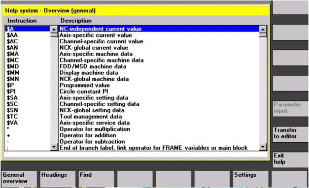
General Overview Apart from context-sensitive help, it is also possible to search independently of context for instructions, descriptive texts or topics. With "General overview" a full overview of the instructions and relevant descriptive text stored in the help system is displayed.
Topics With "Topics" the stored topics are listed for which a functional grouping of the instructions can be displayed. To select a topic, you can either use the cursor keys or enter the topic number in an input box.
INPUT If a topic is selected and you press "Input" or the "Display topic" softkey, the instructions associated with the selected topic are displayed.
Display topic
©Siemens AG 2008 All rights reserved. SINUMERIK 840Di sl/840D sl/840D Operating Manual HMI-Advanced (BAD) - 01/2008 Edition 2-67
2 Operator Components/Operating Sequences
2.6 Calling the help function
 With the "Find" softkey you can define a search text in an input window, which you can search for using
- "Instruction text only"
- "Descriptive text only"
- "Instruction and descriptive texts".
No distinction is made between upper and lower case.
With "Input" or "Start search" a search is made using the defined search text in accordance with the instruction or descriptive part. Any matching instructions or descriptions found during the search are displayed.
Notes for setting the help system in the editor
The editor help uses a standard text file (see Commissioning Manual HMI Advanced), which contains topics and instructions with descriptive text. If you want to create an end user text file for the help in order to record your own instructions/topics, you can enter the path\name of the text file under the "Settings" softkey in an input window as "end user text file". You can also change the context sensitivity under "Settings". You can choose between:
- "Display with same initial wording" (extended context sensitivity) and
- "Display with identical wording" If, for example, in the option "Display with same initial wording" the cursor is located to the right of the instruction "G4", all instructions with the same initial wording, e.g., "G40, G41, G42" are also displayed. With "Display with identical wording" the current instruction, e.g., "G4" is displayed. The settings are activated by restarting the help system.
If you select the individual descriptions in the full overview with the cursor key, you can jump directly to the Programming Guide, for example, with the "info" key, if the symbol for the info key is displayed on the bottom right part of the screen (see Fig. below).
©Siemens AG 2008 All rights reserved.

2 01/2008 Operator Components/Operating Sequences 2.6 Calling the help function 2
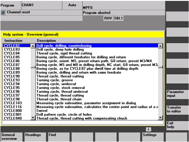
If "Parameter input" appears in the vertical softkey bar, you can assign parameters in an input screen for a particular instruction (e.g., a cycle).
2.6.3 Extended help for program commands
Function
You can call up a help function (quick help) to provide programming support for editing part programs via the "information" key in the program command editor. If the quick help is not sufficient, you can also open the Programming Guide (pdf file) by pressing the "information" key again. The command you are looking for is highlighted in the document.
Sequence of operations
Prerequisite: The cursor is positioned on a programming command (e.g. G01).
You can call up the help function (quick help) in the editor using the "information" key.
Press the "information" key again to open the Programming Guide (pdf file) with Adobe Acrobat Reader.
©Siemens AG 2008 All rights reserved.
2 Operator Components/Operating Sequences 01/2008 2
2.7 Job list
Function
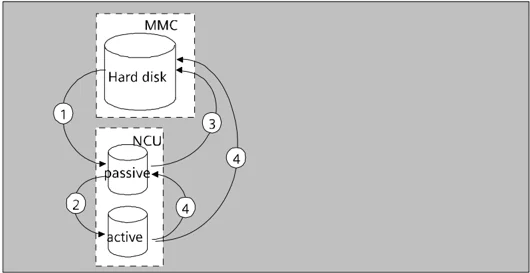
A job list (loading list) can be created for each workpiece. This list contains instructions which prepare the following for the execution of part programs (in several channels if necessary):
- Parallel setup (LOAD/COPY), i.e.:
Main programs and subprograms along with associated data such as
- Initialization programs (INI)
- R parameters (RPA)
- User data (GUD)
- Work offsets (UFR)
- Tool/magazine data (TOA/TMA)
- Setting data (SEA)
- Protection zones (PRO) and
- Sag/angularity (CEC) load or copy from the hard disk of the PCU to the main memory of the NC.
- Preparations for the NC Start (SELECT), i.e.: Select programs in different channels as well as starting preparations for execution
- Parallel clearing (reversed LOAD/COPY), i.e.: Remove/unload main programs, subprograms and associated data from the NC working memory to the hard disk of the PCU
- Backup (in preparation for the next software version)
Notes
Parallel setup, preparations for NC Start, parallel cleanup and backup can also be executed from the PLC. The job list is executed if the workpiece contains a job list of the same name. The job list instructions are activated (see diagram) on
- Parallel setup with "Load" (LOAD/COPY)
- "Select" (LOAD/COPY/SELECT)
- "NC Start" (program is executed and SELECT is activated)
- Parallel clearing with "Unload" (reversed LOAD/COPY)
- "Backup" (in preparation for the next software version)
©Siemens AG 2008 All rights reserved.
2
Operator Components/Operating Sequences 2.7 Job list
Creating the file "Workpiece.JOB" (z.B. SHAFT.JOB)
There are various methods by which job lists can be created:
- While creating a workpiece directory with the function "New", generate a standard job list as a file in this workpiece. The job list syntax is included as a comment in this standard job list. New The "Create templates for job list" field under "Startup/HMI/System settings/Templates" must first be checked. With this method, the file is automatically assigned the name of the relevant workpiece directory, Workpiece.JOB (e.g. SHAFT.JOB).
- Create job lists with different names in an existing workpiece directory with the function "New".
- Job lists can be inserted in an existing workpiece directory. The job list can be modified with the editor.
Notes
You can create your own templates for job lists or standard part programs/subprograms in the directory \Templates\Manufacturer or \Templates\User. The data manager always searches the User directory first, then the Manufacturer directory, and finally the Siemens directory. Job list templates can be stored according to language and system. See Programming operating area: 6.1.5 Templates.
©Siemens AG 2008 All rights reserved.
2 Operator Components/Operating Sequences 01/2008 2
2.7 Job list
2.7.1 Syntax description for job lists

Explanation
The job list syntax consists of 3 instructions
- Load instruction LOAD
- Select instruction SELECT
- Copy instruction COPY (for m:n link only)
Notes
As regards the job list commands, a distinction must be made between an m:n network and a 1:1 link between the HMI and NCs. It is advisable to use the instruction LOAD for a 1:1 link and COPY for an m:n link, at least for global programs and, in particular, cycles used in several NCUs.
Comment
All terms placed inside "brackets" or ";" are comments and are ignored when the job list is processed.
Description of syntax
LOAD [source]
The LOAD instruction loads one or several files from the HMI into the NC working memory, deleting the source file on the HMI. In other words, the files are only stored in one location. This instruction is recommended for a 1:1 link.
[source] is [path]/[name] The path/name defines the relevant path within the file tree of the data manager. Wildcards (i.e., *) may also be used in the name.
Examples:
LOAD * (Loads all files from the workpiece directory of the job list) LOAD /MPF.DIR/* (Loads all files from one directory, e.g., in this case all files from part programs (MPF.DIR)) LOAD PART1.MPF (Loads one file, e.g., PART1.MPF from the currently selected workpiece directory of the job list)
LOAD /SPF.DIR/PART1.SPF
©Siemens AG 2008 All rights reserved.
2 01/2008 Operator Components/Operating Sequences 2.7 Job list 2
(Loads one file from one directory, in this case from the subprogram directory SPF.DIR)
SELECT [source] [destination] [DISK]
The SELECT instruction selects a program for execution. The selected program must be loaded into the working memory of the NC. It can then be started with NC Start. If programs on the hard disk must be executed, then the command must include the keyword DISK.
[source] is the name of the main program which is selected for execution in a specific channel in the NCK.
[destination] A channel must be specified as the destination. CH= Channel number (for a 1:1 link only); or with NETNAMES.INI: Channel name (channels are unambiguously distributed across all NCs); or NC name, channel number Example: CH=2 (2, corresponds to the channel number) CH=Station5 (Station5, corresponds to channel name from NETNAMES.INI) CH=ncu_b,1 (ncu_b, corresponds to the NCU name from NETNAMES.INI 1, corresponds to the local channel number of this NCU)
[DISK] can be optionally specified for program execution from hard disk.
Examples: SELECT PART12 CH=CHANNEL22
SELECT PART12 CH=NCU_2,2 (PART2 is selected in the 2nd channel of NCU_2)
SELECT /shaft1.wpd/side1.mpf CH=2 DISK (Part program PAGE1.MPF of workpiece SHAFT1.WPD is executed from hard disk in the 2nd channel)
©Siemens AG 2008 All rights reserved.
2 Operator Components/Operating Sequences 01/2008 2
2.7 Job list
COPY [source] [destination]
The COPY instruction copies one or several files from the HMI to an NC working memory. The original files remain stored on the HMI. The COPY instruction is executed only if the relevant file does not yet exist at the destination or if it has a different time stamp. This instruction is recommended for an m:n link. If this type of file needs to be modified, it must always be edited on the NC. If the file has been distributed more than once via the job list, and you want the changes to be active in all NCs, you must first unload that file, then edit it, and finally redistribute it via the job list.
[source] is [path]/[name]
[destination] is the NCU/channel address:
The destination can be specified using one of the three address categories. Only the logical name from the NETNAMES.INI file is taken into account.
NC= Name of the NCU Without NETNAMES.INI, it is only possible to specify the NC name with NC=.
CG= Name of the channel group, i.e., copy in every channel of this group (therefore in all NCs to which the channels are assigned). Parameter CG can be specified only if a channel menu is configured.
CH= Name of channel Channel names are only uniquely assigned across all NCs, if a channel menu is configured.
If no destination is specified, the source is copied to the NC currently linked to the HMI. If * is entered as the destination, the source is distributed to all the NCs configured in NETNAMES.INI.
©Siemens AG 2008 All rights reserved.
2.7 Job list
Examples:
COPY * *
(Copies all files from the workpiece of the job list to all NCs that are configured in NETNAMES.INI)
COPY PART12.MPF NC=NCU_2
(Copies one file from the workpiece of the job list to the NC "NCU_2")
COPY /SPF.DIR/PART1.* CG=MILL2
(Copies all files with one name from one directory, e.g., PART1.* from subprograms (SPF.DIR) to a channel group, i.e., to all NCs that have channels from this group assigned to them)
COPY /MPF.DIR/* CH=CHANNEL22
(Copies all files from one directory, e.g., all files from part programs (MPF.DIR) to the NC which has this channel assigned to it.)
2.7.2 Example of a job list with two-channel 1:1 links
Example
If only channel1 and channel2 on NCU1 (1:1 link) were involved in machining of the workpiece, then the job list structure would be as follows:
LOAD /MPF.DIR/Gen.MPF LOAD /Work.DIR/Part1.WPD/WpdGen.MPF
LOAD /Work.DIR/Part1.WPD/ Channel1.MPF LOAD /Work.DIR/Part1.WPD/ Channel1.INI LOAD /Work.DIR/Part1.WPD/ K12.MPF
LOAD /Work.DIR/Part1.WPD/ Channel2.MPF LOAD /Work.DIR/Part1.WPD/ Channel2.INI LOAD /Work.DIR/Part1.WPD/ K22.MPF
SELECT /Work.DIR/Part1.WPD/Channel1.MPF CH=1 SELECT /Work.DIR/Part1.WPD/Channel2.MPF CH=2
The destination is not specified for loading in a 1:1 link, the current NC is the default.
2.7.3 Example of a job list with multi-channel m:n links
Example
HMI1 to two NCs
NCU1 with channel1 and channel2
NCU2 with channel3
Part1.JOB:
COPY /MPF.DIR/Gen.MPF NC=NCU1 (or CH=CHANNEL1) COPY /Work.DIR/Part1.WPD/WpdGen.MPF NC=NCU1 (or CH=CHANNEL1) COPY /Work.DIR/Part1.WPD/Channel1.MPF NC=NCU1 (or CH=CHANNEL1) COPY /Work.DIR/Part1.WPD/Channel1.INI NC=NCU1 (or CH=CHANNEL1) COPY /Work.DIR/Part1.WPD/Ch12.MPF NC=NCU1 (or CH=CHANNEL1)
COPY /Work.DIR/Part1.WPD/Channel2.MPF NC=NCU1 (or CH=CHANNEL2) COPY /Work.DIR/Part1.WPD/Channel2.INI NC=NCU1 (or CH=CHANNEL2) COPY /Work.DIR/Part1.WPD/Ch22.MPF NC=NCU1 (or CH=CHANNEL2)
COPY /MPF.DIR/Gen.MPF NC=NCU2 (or CH=CHANNEL3) COPY /Work.DIR/Part1.WPD/WpdGen.MPF NC=NCU2 (or CH=CHANNEL3)
COPY /Work.DIR/Part1.WPD/Channel3.MPF NC=NCU2 (or CH=CHANNEL3) COPY /Work.DIR/Part1.WPD/Channel3.INI NC=NCU2 (or CH=CHANNEL3) COPY /Work.DIR/Part1.WPD/Ch32.MPF NC=NCU2 (or CH=CHANNEL3)
SELECT /Work.DIR/Part1.WPD/Channel1.MPF CH=CHANNEL1 SELECT /Work.DIR/Part1.WPD/Channel2.MPF CH=CHANNEL2 SELECT /Work.DIR/Part1.WPD/Channel3.MPF CH=CHANNEL3
2.7.4 “Execute job list” operating sequence

Manage data e.g., press the "Manage data" softkey under "Services". The horizontal and vertical softkey bars change.
Position the cursor on the correct workpiece directory. Then execute functions
Load
- "Load" Selection
- "Select" Unload
- "Unload"
If a job list named Workpiece.JOB is stored in a workpiece directory, then the functions are executed for that job list. However, the functions can be executed directly on the job list, e.g., if the directory contains job lists that are named differently from the workpiece.
Additional information

Load
"Load" job list
"Load" means that all the prepared job list instructions are executed. The data is distributed from [Source] to [Destination], to the destination NCs with the instruction LOAD or COPY. The workpiece is then marked as "loaded". SELECT instructions are ignored. If the workpiece/job list is loaded, then the log window displays a list of the files to be distributed. The log window can be displayed in the event of an error. Loading of the job list can then be aborted if necessary.
Marking of files on user interface
If the file is stored only on the hard disk of the HMI, then it is marked as "not loaded". If the file is only located in the working memory of the NC, it is marked as loaded with an "X". If the file is located both on the HMI and the NC, the identifier "X" is only removed when the files are no longer identical. If the files have different time stamps or are of different lengths, the identifier is "!X!".
©Siemens AG 2008 All rights reserved.
2 Operator Components/Operating Sequences
2.7 Job list
\begin{tabular}{ll} Selection & \textbf{"Select" job list} \ & If you select a job list or workpiece with job list, all instructions of the \ & job list are executed. \ & LOAD instructions are executed if the files are still stored on the HMI. \ & COPY instructions are executed only if the files are not stored on the \ & NC or if the file copy on the NC has a different time stamp to the HMI \ & copy. If the time stamps are different, the system asks whether the file \ & should be overwritten. \ & SELECT instructions are executed. \ Unload & \textbf{"Unload" job list} \ & "Unload" means that the instructions of the job list are "undone", the \ & instructions in the job list are executed in reverse order, e.g.: \ & Data which have been loaded to a destination NC with a LOAD \ & instruction are unloaded from [destination] to [source] into the source \ & directory on the HMI. \ & Data which has been loaded to a destination NC with a COPY \ & instruction is deleted in the [destination] if the time stamps are \ & identical. If the file on the NC was changed, the user is prompted \ & whether the version from the NC is to be saved to the HMI. \ & With "Unload" only files are transferred from the passive file system of \ & the NC. If, for example, modifications have been made to the active \ & data in parameters, these must be saved beforehand. \ \end{tabular}
©Siemens AG 2008 All rights reserved.
2 01/2008 Operator Components/Operating Sequences 2.7 Job list 2
2.7.5 Re-naming workpieces with job lists
Function
When you rename a workpiece directory, all the workpiece files under that directory that have the same name as the directory are renamed. If a job list with the name of the directory exists, the instructions in that job list are also renamed. Comment lines remain unchanged. Example: Workpiece directory A.WPD is renamed B.WPD: All files with the name A.XXX are renamed as B.XXX, i.e. the extension is retained. If a job list called A.JOB exists, it is renamed as B.JOB. If this job list contains instructions of file A.XXX and these are located in this workpiece directory, then that file is also renamed B.XXX. Example: If job list A.JOB contains an instruction LOAD/Work.DIR/A.WPD/A.MPF it is renamed as LOAD/Work.DIR/B.WPD/B.MPF However, if a job list contains the instruction LOAD/MPF.DIR/A.MPF or LOAD/Work.DIR/X.WPD/A.MPF the files are not renamed.
Sequence of operations
Manage programs...
The "Manage programs" softkey in the "Program" operating area must be pressed.
Place the cursor on the workpiece directory that you want to rename.
Rename
The "Rename" dialog window opens.
Enter the new name.
©Siemens AG 2008 All rights reserved.
2 Operator Components/Operating Sequences 01/2008 2.7 Job list
2.7.6 Copying workpieces with job lists
This function only applies to the "Program" operating area. When you copy under "Services", the names remain unchanged.
Sequence of operations
The "Manage programs" softkey in the "Program" operating area must be pressed.
Position the cursor on the file that you want to copy and press the "Copy" softkey. The file is marked as the source for copying.
Press the "Insert" softkey, specify another name if required
and confirm with "OK".
2.7.7 Archiving workpieces with job lists in the case of M:N
Function
When archiving workpieces that contain job lists of the same name, in the case of M:N, you are asked whether the job lists to be unloaded are to be executed. You can terminate the action with "Abort", otherwise all job lists are executed and archiving is then started.
Sequence of operations
In the "Services" operating area, press the "Data from" softkey. The "Programs/Data" file tree is displayed. The vertical softkey bar changes. Please refer to Chapter "Reading out data" in "Services" operating area for additional sequences of operation.
Example of Operation
3.1 Typical operating sequence
To provide support for entry-level users or an orientation guide for others, this overview uses a typical operating sequence (from control system power-up to back-up of a user-generated part program) to explain how the functions described can be located.
| Step | In section/ subsection |
|---|---|
| setting-up | |
| • Switch on machine | 1.3 |
| • Reference point approach | 4.3 |
| • Clamp workpiece/blank | |
| • Select tools | |
| • Define workpiece zero for coordinates | |
| • Enter work offset | 5.6.2 |
| • Enter tool offsets | 5.2.7 |
| • Calculate speeds and feedrates | 4.2.4 |
| • Define a reference point (scratching) | 4.4.6 |
| Enter and test a program | |
| • Create part program or | 2.6.6 |
| • Import via external data interface | 7.1 |
| • Select a part program | 6.9.5 |
| • Execute a trial program run (without a tool) | |
| – Start a part program (e.g., in single block) | 4.2.1 |
| – Revise part program using program editing function or diagnostics guide/help | 4.6.78.2 |
| • Optimize a part program | 6.6 |
| Machining the workpiece | |
| • Use tool | 5.3 |
| • Execute machining program | |
| Store a program | |
| • Save a part program | 6.10 |
| – To hard disk or | 7.2 |
| – Export via external data interface | 7.1 |
SINUMERIK 840Di sl/840D sl/840D Operating Manual HMI-Advanced (BAD) - □□/□□□□ Edition
3 Example of Operation 01/2008 3 3.1 Typical operating sequence
Notes
3-82 © Siemens AG 2008 All rights reserved.

Machine operating area
-
4.1 CNC data structure ........ 4-85
-
4.1.1 Modes and machine functions ........ 4-86
-
4.1.2 Modes group and channels ........ 4-88
-
4.1.3 Cross-channel status display via symbols ........ 4-89
-
4.1.4 Two-channel display ........ 4-90
-
4.1.5 Mode selection, mode change ........ 4-91
-
4.2 General functions and displays ........ 4-94
-
4.2.1 Start/stop/abort/continue part program ........ 4-94
-
4.2.2 Displaying the program level ........ 4-95
-
4.2.3 Switching over the machine/workpiece coordinate system (MCS/WCS) ........ 4-96
-
4.2.4 Displaying several transverse axes ........ 4-98
-
4.2.5 Displaying axis feedrates ........ 4-99
-
4.2.6 Display G functions, transformations and swivel data ........ 4-100
-
4.2.7 Displaying auxiliary functions ........ 4-101
-
4.2.8 Displaying modal M functions ........ 4-101
-
4.2.9 Displaying spindles ........ 4-103
-
4.2.10 Handwheel ........ 4-104
-
4.2.11 Status of the synchronized actions ........ 4-105
-
4.2.12 Preset ........ 4-107
-
4.2.13 Setting the actual value ........ 4-108
-
4.2.14 Inch ↔ Metric switchover ........ 4-109
-
4.3 Reference point approach ........ 4-111
-
4.4 JOG mode ........ 4-114
-
4.4.1 Function and main screen ........ 4-114
-
4.4.2 Traversing axes ........ 4-117
-
4.4.3 Inc: Increment ........ 4-118
-
4.4.4 REPOS (repositioning) ........ 4-119
-
4.4.5 SI (Safety Integrated): User agreement ........ 4-120
-
4.4.6 Scratching ........ 4-121
-
4.4.7 Displaying system frames ........ 4-124
-
4.5 MDA mode ........ 4-127
-
4.5.1 Function and main screen ........ 4-127
-
4.5.2 Saving the program, file function ........ 4-129
-
4.5.3 Teach in ........ 4-130
-
4.6 Automatic mode ........ 4-132
-
4.6.1 Function and main screen ........ 4-132
-
4.6.2 Program overview ........ 4-134
-
4.6.3 Loading and unloading the workpiece/part program ........ 4-135
-
4.6.4 Protocol: Program loading list ........ 4-136
-
4.6.5 Executing from the hard disk ........ 4-137
-
4.6.6 Accessing an external network drive ........ 4-138
-
4.6.7 Program editing ........ 4-140
4 Machine operating area 01/2008 4
- 4.6.8 Setting the block search/search target ........ 4-141
- 4.6.9 Accelerated external block search ........ 4-145
- 4.6.10 Block search in Program test mode, multi-channel ........ 4-148
- 4.6.11 Overstore ........ 4-150
- 4.6.12 Program control ........ 4-152
- 4.6.13 DRF offset ........ 4-156
4.1 CNC data structure
Function
The following components exist:
- NC with part program memory
- HMI with hard disk
Use the "Load" - "Unload" softkeys to transfer the data to the NC or from the NC to the hard disk.
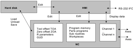
Data in the NC memory are retained when the control power supply is switched off. Only one copy exists of programs that are loaded from the hard disk to the NC memory. The program memory in the NC is limited (see Chapter 9.3 under “NC memory”).
4 Machine operating area
4.1 CNC data structure
4.1.1 Modes and machine functions
Function
The Machine operating area includes all functions and influencing variables which initiate actions on the machine tool or measure its status.
There are three different modes in this area:
- JOG: JOG is the mode required for manual operation and setting up of the machine. The setup functions provided are "Reference point approach", "Repositioning", "Handwheel" or "Traverse in preset increments" and "Redefine control zero" (preset).
- MDA: Semi-automatic operation Part programs can be set up and processed block by block in this mode. The tested blocks can then be stored in the part program. In Teach-in mode, positions can be traversed and stored to generate motion sequences, which are then stored in the MDI program.
- Automatic: Fully automatic operation Part programs are executed fully automatically in Automatic mode, i.e., part programs are selected, started, corrected, selectively controlled (e.g., single block) and executed in Automatic.
Select machine area
 or
You can switch to the "Machine" area at any time from any of the other operating areas simply by pressing the "Machine area" key.
When you switch on the control, it is usually in the "Machine" operating area and in "JOG" mode. Please consult the documentation provided by the machine manufacturer!
Machine manufacturer
The state after power-up can be configured and might therefore deviate from the default.
In "JOG" mode you can select the following machine functions via the machine control panel or softkeys in the main menu:
Machine functions
Inc (traverse in preset increments)
 Repos (repositioning according to a defined position)
4
Machine operating area
4.1 CNC data structure
Ref (reference point approach to coordinate machine and control zero points)
In "MDA" mode, it is possible to select "Teach-in" (storage of motion sequences in a part program through position approach) by pressing the MCP key.
Preparation for production
To start actual production, some preparatory measures must be taken:
- Set up the tools and workpiece
- Traverse the tools/workpiece to the start position specified in the setup plan
- Download the part program to the control memory
- Check/enter the work offsets
- Check/enter the tool offsets

4 Machine operating area 01/2008 4
4.1 CNC data structure
4.1.2 Modes group and channels
Function
Every channel behaves like an independent NC. A maximum of one part program can be processed per channel.
- Control with one channel: One mode group exists.
- Control with several channels: Channels can be grouped to form several "mode groups." Example: Control with 4 channels, where machining is carried out in 2 channels and 2 other channels are used to control the transport of the new workpieces. Mode Group1 Channel 1 (machining) Channel 2 (transport) Mode Group2 Channel 3 (machining) Channel 4 (transport)
Technologically-related channels can be combined to form a mode group. Axes and spindles of the same mode group can be controlled by one or more channels. An operating mode group is in one of "Automatic", "JOG" or "MDI" operating modes, i.e., several channels of an operating mode group can never assume different operating modes.
Channel status via symbol The channel status and the channel operational messages are output with symbols in the channel status line:
Channel status Channel interrupted Channel active Channel RESET
Channel operational messages Stop: Action is required (e.g., cancel feed disable).
4
4.1.3 Cross-channel status display via symbols
Function
The status of channels, feedrate and spindles are output for a number of channels via symbols in the program status line as well as the machine status, if applicable - or the machine status only.
The machine manufacturer can customize the display; custom symbols can be displayed in addition to the standard symbols.
Initially, this only applies to permanent one-to-one links involving one HMI and one NCK.
Machine manufacturer
Please follow the instructions of the machine manufacturer.
The following SINUMERIK-specific status displays are available:
- Channel status with overlaid spindle and feedrate stop
- Channel status with overlaid feedrate stop
- Channel status
- Spindle status
Significance of colors:
Red Machine/control stopped
Yellow Waiting for operator to take action
Green Machine/control running
Gray Miscellaneous
Channel status
Channel interrupted
Channel active
Channel RESET
Feedrate status
Feedrate is not enabled
Spindle status
Spindle rotating counterclockwise or clockwise
or
Spindle is not enabled
Spindle stop
Application example with 4 channels and 2 spindles:
Maschine CHAN1 ◇CHAN2 AUTO \WKS.DIR\DAUERTE_CYC950.WPD DAUERTE_NUMBERFEHL.MPF Kanal unterbrochen 1 M 2 3 4 S1 S2 Halt: Satz in Einzelsatz beendet SKP1 DRY ROV SBL1 M01 M17 DRF PRT
© Siemens AG 2008 All rights reserved. SINUMERIK 840Di sl/840D sl/840D Operating Manual HMI-Advanced (BAD) - 01/2008 Edition
Machine operating area 4.1 CNC data structure 4

