5 Parameters operating area 01/2008 5
5.3 Tool management
Note
The data you enter are always updated immediately (without prompting). You can edit the properties of the new tool by pressing the "Tool details" softkey.
It is not possible to edit the data directly in the table.
You can only edit the name and type of a tool by selecting Create New, not via Tool details.
To change a name, you have to create a new tool and delete the old one.
V ertical softkeys (working offset list)
(Names assigned by user)
Selection of a table structure configured by the user (if configured), e.g.:
- General data
- Geometry data
- Wear data
You can display and edit the complete data of a tool (as in the magazine list).
Find an entry with a specific D number/DL number.
- Enter the D number and DL number you want to find in the search window.
- Confirm with "OK". If a matching entry is found, the cursor jumps to the corresponding line. If you have not specified a DL number, the cursor is positioned on the first line of the matching tool.
The D number of the current tool is determined and displayed.
5 01/2008 Parameters operating area 5.3 Tool management 5
5.3.2 Displaying/editing tool data
Function
You can view and edit the tool data of the tool selected in the lists.
You can edit the following cutting edge data:
- Corrective values
- Monitoring data
- User data
Sequence of operations
Press the "Tool management" softkey. The list configured by the machine manufacturer appears (e.g., the magazine list). The horizontal and vertical softkey bars change.
Select the appropriate list via softkey:
- "Magazine list"
- "Tool list"
- "Working offset list"
Position the cursor bar on the appropriate tool. The tool is selected. Notice: Please ensure that the channel in which the offsets are to be applied is displayed.
Select the "Tool details" softkey. The input screen for "Tool details" appears. The vertical softkey bar changes again.
The following functions are available:
- Create new cutting edges
- Edit cutting edge data
- Edit monitoring data
- Edit local offsets (DL numbers)
- Delete cutting edges
5 Parameters operating area 01/2008 5
5.3 Tool management
You can edit the following data in the input screen :
- Location type
- Location coding
- Monitoring type
- Status (enabled, disabled, measured, etc.)
- Tool user data (Omit; x = 1...10)
- D numbers
- Tool name
- Duplo number
- Tool type, only in magazine list and tool list
Note The tool data name, duplo number and type can only be changed if the option has been enabled by the machine manufacturer. If the option is not activated you cannot make any changes. These data are permanently defined when a new tool is created.
New cutting edge New cutting edges are created for the displayed tool. A cutting edge number to which no D number has yet been assigned is automatically selected in the table. When you have allocated a D number, the value is displayed in red (the cutting edge has not yet been created). Select "Cutting edge data" in the vertical softkey bar. The selected cutting edge is created. Default values are assigned to the cutting edge data and the corresponding table is displayed. Enter any necessary changes.
You can use the "Cutting edge +" and "Cutting edge -" softkeys to display and, if necessary, edit the data of the other cutting edges. The data are updated immediately.
Press the "<< softkey to return to the Tool details input screen. The new cutting edge is defined. The display color changes.
Additional information
If twelve cutting edges have already been defined for the tool, you must delete one of the cutting edges (via softkey) before you can create a new one.
The machine manufacturer can limit the maximum permissible number of cutting edges for each tool to a smaller number. The default setting is nine cutting edges.
5
Parameters operating area
5.3 Tool management
5
A new cutting edge can be added to a tool at any time (even if the tool is already located in the magazine). Select "New cutting edge" and enter the cutting edge data.
Edit tool data
Press the "Cutting edge data", "Mon. data" and "Local offsets" softkeys to display tables for editing the respective data. You can move freely between the individual tables. The name, Duplo number and type of tool and all defined cutting edges (#1...#12) are displayed. Use the "Cutting edge +" and "Cutting edge -" softkeys to toggle between the cutting edges. Press "<<” to return to the "Tool details" input screen.
Note
When you edit the data, the new data is saved immediately. The "<<” softkey only changes the display. The cutting edge data and tool offsets of the currently selected cutting edge are displayed and can be edited.
Cutting edge data
You can edit the following data:
- Cutting edge user data (OEM_Sx; x = 1...10)
- Tool offsets
- Geometry
- Wear
- Basic offset
- Cutting edge position (for turning tools)
- Tool clearance angle (for turning tools)
You can define the value of Length1, Length2, Length3 and Radius1 for every parameter.
Monitoring data
The monitoring data of the currently selected cutting edge are displayed and can be edited. When you have selected a cutting edge, define the actual value, setpoint and warning limit monitoring data for the following parameters:
- Quantity
- Tool life
- Wear

5 Parameters operating area
5.3 Tool management
Loc. dep. offsets The tool offsets (identical to the cutting edge data table) and the local offsets of the currently selected cutting edge are displayed and can be edited.
The following options are available:
- Values can be defined for Length1, Length2, Length3 and Radius1 for each parameter.
- Up to six local offsets (DL1...DL6) are possible (according to the machine manufacturer's configuration).
- Setup values and wear values can be defined for each offset.
Edge + In the individual tables, this softkey displays the data/offsets of the next cutting edge for editing.
Edge - The data/offsets of the previous cutting edge are displayed and can be edited.
Delete edge In the table, select the cutting edge you want to delete (by positioning the cursor). The cutting edge is deleted when you activate the softkey.
Important: There is no separate prompt.
The D number is removed from the table and can be reallocated.
<< Terminates input of the tool data and returns to the table displayed previously.
Note You can enter individual tool data items directly in the current list, provided you have the necessary access authorization and the data are displayed in the list (the list structure is configurable).
Select the value to be edited and enter the required data. The system automatically switches to edit mode.


5 01/2008 Parameters operating area 5.3 Tool management 5
5.3.3 Change in the significance/representation of tool wear values
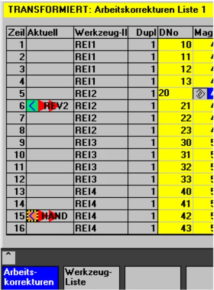
Symbols In the tool list screens, additional symbols indicate whether special features have to be taken into account for the current tool according to G code 56 and setting data SD 42935: WEAR_TRANSFORM.
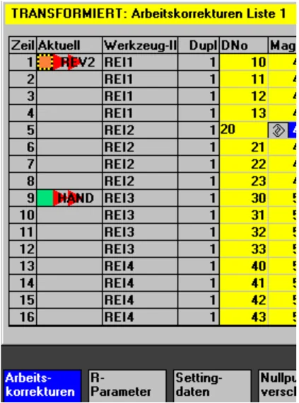
The G56 reset value is TOWSTD and at least 1 bit in $SC_WEAR_TRANSFORM is set. The current tool for channel "REV2" is indicated in row 1. The current value of G56 on channel "REV2" deviates from the G56 reset value (. Row 9 displays the current tool for channel "HAND". There the current value of G56 is equal to the reset value ( ).
SINUMERIK 840Di sl/840D sl/840D Operating Manual HMI-Advanced (BAD) - 01/2008 Edition 5-195


5 Parameters operating area 5.3 Tool management 5
Symbols
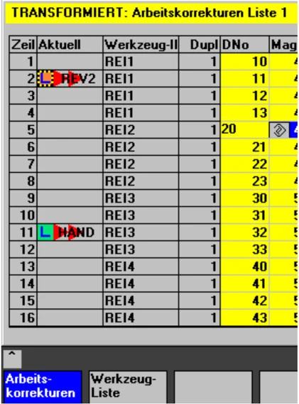
The G56 reset value is TOWMCS and $SC_WEAR_TRANSFORM is set. The current tool for channel "REV2" is indicated in row 2. The current value of G56 on channel "REV2" deviates from the G56 reset value ( ). Row 11 displays the current tool for channel "HAND". There the current value of G56 is equal to the reset value ( ).

5 01/2008 Parameters operating area 5.3 Tool management 5
Symbols The G56 reset value is TOWWCS and $SC_WEAR_TRANSFORM is set. The current tool for channel "REV2" is indicated in row 6. The current value of G56 on channel "REV2" is the same as the reset value ( ). Row 15 displays the current tool for channel "HAND". Here, the current value of G56 deviates from the G56 reset value ( ).
Additional information
Additional information can be found in: Function Manual Tool Management
SINUMERIK 840Di sl/840D sl/840D Operating Manual HMI-Advanced (BAD) - 01/2008 Edition 5-197


5.3.4 Grinding data expansion
Function
If the selected tool is a grinding tool, a vertical softkey 6 "Grinding parameters" is provided in the following:
- Tool details main screen
- Tool details cutting edge data (sub)screen
- Tool details monitoring data (sub)screen
When this softkey is pressed, a display appears where grinding parameters can be:
- Display
- Edit
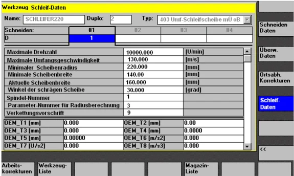
This display contains the following:
Top section:
- Tool name
- Duplo number
- Type
- Cutting edge navigation bar
as in the "Cutting edge data" display for tool details
(The data is only displayed and cannot be modified)
Middle section:
The data correspond to the system variables entered for grinding.
| Variable for | Unit | Name of identifier |
|---|---|---|
| Spindle number | - | $TC_TPG1 |
| Chaining rule | - | $TC_TPG2 |
| Minimum wheel radius | [mm, in] | $TC_TPG3 |
| Minimum wheel width | [mm, in] | $TC_TPG4 |
| Current wheel width | [mm, in] | $TC_TPG5 |
| Maximum speed | [rpm] | $TC_TPG6 |
| Maximum peripheral speed | [m/s, ft/s] | $TC_TPG7 |
5
Parameters operating area
5.3 Tool management
5
Angle of the inclined wheel [degrees] $TC_TPG8 Parameter number for radius - $TC_TPG9 calculation/compensation parameter for GWPS
Additional information
For information on NC variables, please refer to the Function Manual /FB/, W4 Grinding-specific tool offset and monitoring.
Bottom section: Tool OEM data are displayed as on the main screen for tool details. The tool OEM data can be edited on both the grinding parameters screen and the main tool details screen. The designation and the unit in the OEM data can be parameterized in the relevant language. The bottom section of the display is only available if tool OEM data are available on the NC.
Scroll bar A scroll bar appears next to the middle and bottom sections if the bottom section is displayed.
The grinding parameters screen and the softkeys are only displayed if the tool is a grinding tool (tool type between 400 and 499). Access rights are checked for grinding parameters. Default access is "All". All tool cutting edges are of the same type. The same applies to the dresser cutting edges of grinding tools.
Tool types The tool types for grinders are 4xy in accordance with /FB/, W4. They are available in displays/functions for:
- Tool cabinet
- Tool catalog
- Cutting edge parameters in tool details
- Lists (magazine list, tool list, working offset list)
Limitations
- The tool-specific grinding parameters cannot be displayed in the list displays.
- They are not saved in the tool cabinet/tool catalog.
- They are not transferred via code carrier/SINCOM.
- The extension is available in HMI Advanced Version 6.2 or later.

5 Parameters operating area 5.3 Tool management
5.3.5 Load
Function
You can load a tool in one of the following ways:
- You can enter the individual tool data directly in the list.
- You can import tool data from existing tools.
You can load a tool from the "Magazine list" or the "Tool list".
-
Loading a tool from the "Magazine list" To edit tool data directly in the list, you must first find a suitable empty location for the tool (use the softkeys). You can then enter the data directly in the list.
You can also load all existing tools into the magazine. You load the associated tool data: – From the master data catalog – From the tool cabinet – From the code carrier (if one exists) or – From the host computer (if one is connected). In this case, the system automatically tries to find a suitable empty location for the selected tool.
-
Loading a tool from the "Tool list" Tools for which data are already stored in the TO memory can be loaded into the magazine. The magazine location is selected either by searching for an empty location or by entering a magazine number and location number in the corresponding columns of the list.
5
Parameters operating area 5.3 Tool management
Additional information
In the lists, you can parameterize a filter for loading tools. A list display appears for which you can parameterize a filter for the tool ID, duplo number and tool type. The list then displays the tools in the tool cabinet that meet the filter criteria. By selecting it from the list, you accept the tool.
Sequence of operations (loading from the "Magazine list")
Tool managem. Press the "Tool management" softkey. The "Magazine list" is displayed. The horizontal and vertical softkey bars change.
Magazine list The "Magazine list" is selected. The appropriate magazine is selected.
Load Press the "Load" softkey. The vertical softkey bar changes again.
Manual data input (with search for empty location)
If you want to enter data directly in the table, you must first find a suitable empty location in the magazine.
There are four methods by which you can find an empty location for different tool sizes in combination with location types:
- Directly in the magazine list ("Manually").
- Via a user-defined location e.g., "oversize" (name configured by machine manufacturer)
- Via the "Find empty location" softkey
- Via the "To loading point" softkey
Additional information
Values are checked for validity when you enter a tool type in the lists. Only known tool types are permitted.
Searching directly in the magazine list
Position the cursor on the location of your choice in the magazine list.
Search via user-defined location (example)
The assignment of the softkeys is configured by the machine manufacturer.
5 Parameters operating area
5.3 Tool management
- "Normal" (name configured by machine manufacturer)
- "Large" (name configured by machine manufacturer)
- "Oversize" (name configured by machine manufacturer)
- "Normal and heavy" (name configured by machine manufacturer)
The system searches for a suitable empty location. The cursor bar is automatically positioned on the magazine location found in the "Magazine list".
Search via the "Find empty location" softkey
Enter the "Tool size" and "Location type" in the query window. If more than one loading point is configured, select the desired loading point from a query window. The system searches for the corresponding empty location. The cursor bar is automatically positioned on the magazine location found in the "Magazine list".
Search via the "To loading point" softkey
You have found an empty location in front of the current loading point. When you press "To loading point" the cursor is automatically positioned at this location.
Enter data
If the desired empty location is found after a search operation, the system switches to edit mode and the softkey bar changes. When you search for an empty location manually, the system switches to edit mode as soon as you start entering the data on the keyboard.
You can use the "Tool details" display to edit the data of the tool to be loaded (if necessary). If the tool has not yet been created, it is created automatically when you call the input screen.
Load/input mode is canceled. A tool created via "Tool details" or "Start" is deleted. You can search for another empty location.
The loading operation is initiated. If the tool has not yet been created, it is created automatically.
5 01/2008 Parameters operating area 5.3 Tool management 5
Import tool data
If data are still missing for loading, the tool details input screen appears. The missing data are initialized with default values and can be edited if necessary. Start the loading operation again afterwards. In addition to direct data entry, there are various ways of importing tool data belonging to tools which have already been defined and of subsequently loading these tools:
-
Read-in the data in from a code carrier (if one is installed) Data from CC
-
Read-in the data in from a host computer (if one is installed) Data from host
-
Select the "Tool from cabinet" menu. Select the tool in the tool cabinet. The tool data are read from there. Tool in cabinet
If not all of the softkeys are visible, change the display by pressing the appropriate key on the operator panel front.
When you have defined the source for loading, the system automatically tries to find a suitable empty location for the tool to be imported. The vertical softkey bar changes.
If no location is found, an error message is displayed.
You can use the "Tool details" display to edit the data of the tool to be loaded (if necessary). If the tool has not yet been created, it is created automatically when you call the input screen. Tool details
Load/input mode is canceled. A tool created via "Tool details" or "Start" is deleted. You can search for another empty location. Abort
The loading operation is initiated. If the tool has not yet been created, it is created automatically. Start
"Load directly to spindle" is possible if the cursor is positioned on the spindle buffer location.
5 Parameters operating area 01/2008 5.3 Tool management
Sequence of operations (loading from the "Tool list")
Tool list The "Tool list" is selected. The appropriate tool is selected.
Load Press the "Load" softkey. The vertical softkey bar changes.
Find empty location Search for an empty location for a tool which has already been created or enter the desired location and magazine number in the list.
The location found is entered under the magazine/location number.
Abort The loading operation is not initiated. The main screen appears.
Start The loading operation is initiated.
5.3.6 Unload
Function
This function allows you to unload a selected tool and to save its data.
Sequence of operations
Tool managem. Press the "Tool management" softkey. The "Magazine list" is displayed. The horizontal and vertical softkey bars change. You can unload a tool from the "Magazine list" or the "Tool list".
The sequence of operations is the same for both methods.
5
Parameters operating area 5.3 Tool management
5
Select the appropriate list via softkey:
- "Magazine list" A tool is to be physically removed from a magazine location. You can configure whether the corresponding NC block is also removed from the TO memory. Select the magazine and the tool to be unloaded (select the tool with the cursor).
or
- "Tool list" The NC block is to be unloaded from the memory. Select the tool to be unloaded (select the tool with the cursor).
Select the "Unload" softkey. The vertical softkey bar changes.
The tool data of the selected tool are stored in the tool cabinet on the hard disk. This allows you to load the tool with the same data again at a later point.
If a code carrier is installed, the tool data are automatically stored there. This allows you to load the tool with the same data again at a later point.
The selected tool is unloaded. The corresponding line is deleted from the magazine list. The entries in the magazine number and location number columns are removed from the tool list.
"Unload directly from spindle" is only possible if the buffer is selected and the cursor is positioned on the location of the spindle.
To exit the screen without unloading the tool, select another display in the vertical softkey bar before pressing "Start".
The tool data of the selected tool are deleted from the TO memory. If the tool is in a magazine location, it is unloaded and deleted.
If a host computer is connected, the data are transferred to the host computer each time a tool is deleted or unloaded.

5 Parameters operating area 5.3 Tool management
5.3.7 Relocating

Function
This function allows you to move a selected tool from one location to another.
Sequence of operations
Press the "Tool management" softkey. The "Magazine list" is displayed. The horizontal and vertical softkey bars change.
You can relocate a tool from the magazine list or the tool list. The sequence of operations is the same for both methods.
Select the appropriate list via softkey:
- "Magazine list" Select the magazine and the tool to be relocated (position the cursor on the magazine location containing the tool). or
- "Tool list" Select the tool to be relocated (position the cursor on the tool). This tool must already have been loaded (entry in the magazine number and location number columns).
When you select the "Relocate" key, the "Relocate tool" window opens.
There are 2 methods by which you can select the new location for the tool:
- Enter the magazine and location numbers in the "Relocate tool" window. or
- Press the "Find empty location" softkey and select the desired data in the window.

5
Parameters operating area 5.3 Tool management
5

The tool is not relocated.
Start
The tool is relocated to the new empty location.
Use magazine number 9998 to move a tool to or from a spindle location.
When relocating from the buffer, the previous location information is entered by default. This applies to fixed-location-coded and variable tools.
5.3.8 Tool master data in the tool catalog
Function
You can create tool master data in the tool catalog. A set of data can be created for every tool in use.
Advantage
Master data which apply to the tool, regardless of which cutting edge you use, do not have to be reentered for each tool, but can be copied from the tool catalog (in the tool cabinet) for each tool used.
Ideal tools
The tool catalog contains only "ideal" tools. "Ideal" tools are characterized by the relevant tool "master data" (i.e., with ideal tool dimensions, no wear, etc.). An "ideal" tool is uniquely defined by its "Tool name".
5 Parameters operating area
5.3 Tool management

Sequence of operations
Press the "Tool management" softkey. The horizontal and vertical softkey bars change.
The horizontal softkey bar is expanded.
Press the "Tool catalog" softkey. The vertical softkey bar changes again. The tool details of the tool catalog are displayed.
You can use the list fields to display the available standard tools and tools which have already been defined or to create new tools.
Create tool data
Proceed as follows to create the tool data:
- Select the desired technology in the appropriate list field (e.g., drilling tools, milling tools).
- Define the tool type in the second list field (e.g., twist drill).
- Activate this softkey to create a new tool. You can edit the field for the tool name.
- Enter a tool name.
- In the open window, "Tool details", define the tool properties (in "Tool size" you define the total number of tool half locations occupied by the tool).
- Select "Abort" to discard the settings. The tool is not created.
- Save your data with OK. The new tool is created.
Display /edit tool data
In addition to the tool master data already defined, you can enter default settings in the tool catalog for all the other tool data (e.g., cutting edge data, user data). You can edit this data later. Duplo number 0 is allocated to the tool.

5 01/2008 Parameters operating area 5.3 Tool management 5
i Tools in the tool catalog are used as a basis for real tools. It is recommended to define only data actually required in that exact form for several real tools. This helps to minimize the amount of changes required later.
Tool data are displayed and edited as follows:
-
Tool offset data (cutting edge data) Offsets The tool offset data window is displayed. The data of the first cutting edge are listed in a table. The vertical softkey bar changes. Enter the required settings.
The following functions are available for editing the cutting edge data:
Edge + The cutting edge data of the next defined cutting edge are displayed in a table.
Edge - The data of the previous cutting edge are listed.
New A new cutting edge is created for the tool.
Delete The current cutting edge and all the data defined for the cutting edge are deleted after a prompt.
Abort Select "Abort" to discard the changes. No new cutting edge is created.
OK Save the cutting edge data with "OK". A new cutting edge is created (if defined).
-
Cutting edge user data (if configured) Cut. edge user data Switches to the "Cutting edge user data" input screen. Up to 10 user-specific cutting edge data are displayed here. Enter the required settings in the table.
-
Tool user data (if configured) Tool user data Switches to the "Tool user data" input screen. Up to 10 user-specific tool data are displayed here. Enter the required settings in the table.
5 Parameters operating area 01/2008 5
5.3 Tool management
Additional functions
The following functions are also available in the tool catalog:
Copy The data of the tool are copied and a new tool is created with identical data. You are prompted to enter a name for the new tool.
Delete The currently selected tool is deleted after a prompt. All data relating to this tool are lost.
Additional information
The "Tool offset data", "Cutting edge user data" and "Tool user data" softkeys are always displayed when you edit the tool details. This allows you to toggle between the individual tables as required.
The tool data for tools of the catalog can be edited at any time.
5.3.9 Tool offset data in the tool cabinet

Function
You can create tool offset data in the tool cabinet. A set of data can be created for every tool in use. The "ideal" master data defined in the tool catalog can be copied to the tool cabinet.
Advantage Tools which have already been used can be stored in the tool cabinet before they are unloaded from the magazine. The current data, such as the remaining tool life, remain stored and can be accessed again the next time the tool is loaded. You can also enter the tool data of tools which you plan to use in future (like the tools in a real tool cabinet).
Real tools The tool cabinet contains "real" tools only. "Real" tools (i.e., real tool dimensions, with wear, etc.) are characterized by the relevant tool "offset data".
A "real" tool is uniquely defined by its "tool name" and the associated "Duplo number". It is the "Duplo number" that assigns actual data to a "real" tool.
5
Parameters operating area 5.3 Tool management
Sequence of operations
Press the "Tool management" softkey. The horizontal and vertical softkey bars change.
The horizontal softkey bar is expanded.
Press the "Tool cabinet" softkey. The vertical softkey bar changes again.
Create-tool offset data
In order to add a tool to the tool cabinet, it must first be created in the tool catalog. You create a real tool by defining a new Duplo number in the tool cabinet.
Please proceed as follows:
- Select the desired technology, tool type and tool successively in the appropriate list fields.
- Define the Duplo number. The tool master data are loaded into the tool cabinet. The editing functions are available.
- Use the vertical softkeys to make all the necessary changes to the cutting edge data and user data.
- Select "Abort" to discard the settings. The tool is not created.
- Select "OK" to save the changes. The tool is created with the current offset data.
The defined tool data can be edited at any time. You can overwrite the data for the current tool or allocate a new Duplo number to create a replacement tool.

5 Parameters operating area 01/2008
5.3 Tool management
Display/edit tool data
The vertical softkeys can be used to display and edit the data for tools already stored in the cabinet:
Offsets
- Tool offset data (cutting edge data) Enter the required offset values. The design of the vertical softkeys is identical to the tool catalog softkeys (see previous section under offsets).
A new cutting edge can be added to a tool at any time (even if the tool is already located in the magazine).
Cut. edge user data
- Cutting edge user data (if configured) Up to 10 user-specific cutting edge data entries are displayed here. Enter the required settings in the table.
Tool user data
- Tool user data (if configured) Up to 10 user-specific tool data entries are displayed here. Enter the required settings in the table.
Abort
- Select "Abort" to discard the settings. The data retain their old values.
OK
- Press "OK" to accept the changes. The data are updated.
Additional functions
The "Delete" function is also available in the tool cabinet. It is not possible to copy or create a new ideal tool here (only in the tool catalog).
Delete The currently selected tool is deleted from the tool cabinet after a prompt.
All data of the tool with this Duplo number are lost. The master data in the tool catalog are not affected (tool with Duplo number 0).
5
Parameters operating area 5.3 Tool management 5
Additional information
The "Tool offset data", "Cutting edge user data" and "Tool user data" softkeys are always displayed when you edit the tool details. This allows you to toggle between the individual tables as required.
A tool entered in the cabinet can be loaded to a magazine location via the "Tool from cabinet" softkey.
5.3.10 Job processing of tools

Function
Applications
The "Batch processing of tools" function allows the user to:
- Load and unload, delete and store tools in the cabinet in a single process for several tools.
- Monitor the progress of execution.
- Utilize the "Reactivate tools" function.
Parameterizable filters are used to select the tools. These enable you to create a snapshot of the tool data inventory of the NC containing all tools with the properties specified in the filter definition, e.g., all tools with particular tool status bits set, with a particular tool type, with a certain length, with particular OEM data, etc. The search is carried out exclusively in the NC.
Batch processing for tools can be initiated via the operator interface and monitored there. Loading, unloading and reactivation can take place in the background, even if the associated interface is not active. The filter definition and some of the interface settings are carried out in the paramtm.ini and patm_xx.ini files for tool management.
5 Parameters operating area 01/2008 5.3 Tool management
Application The machine operator can use the "Batch processing for tools" function to perform the following operations for sets of tools according to predefined filter criteria:
- Load
- Unload and
- Reactivate The function is available within the tool management. The parameters and other settings for the filter criteria are made in the paramtm.ini file without a separate operator interface.
Functional Description Operator interface: The "Batch processing for tools" function is selected via the "Filter lists" horizontal softkey from the basic states of the magazine and tool lists in the tool management. There are three states relating to "Batch processing for tools", which are represented by different screens:
- Filter selection
- Displays the hit list, enables tool selection and selection and start of batch processing in 2 screens: Load batch list and standard batch list.
- Batch execution Each TOA (data area for tool offsets) has a separate state. You can exit the "Filter lists" in these states and display different tool management screens or switch to other operating areas. The next time you press the "Filter lists" horizontal softkey, the screen for the noted state is displayed. The 2nd state "Hit list" stores the hit list and the tool selection as a snapshot. The 3rd state "Batch execution" stores the data for the selected tools and the batch type. You can exit the "Filter lists" during batch processing. After returning to the "Filter lists", the new status of batch processing is displayed. The status of the batch as a whole and the states of the individual batch elements are visible.
Paramtm.ini You can set the user rights for the softkeys involved in the paramtm.ini file (section [ACCESSLEVEL], entries "SKB...").
The filter lists are parameterized in the paramtm.ini file in the [BatchTools] section. Country-specific sections are parameterized in the "language\patm_xx.ini" file in the section [BatchTools],"xx" stands for the 2 letters of the country code.
5-214 © Siemens AG 2008 All rights reserved.