6
"Program" operating area
6.7 Free contour programming
6
Notice
Upon recompilation only the contour elements that were created with free contour programming are regenerated. In addition, only the texts that were added using the "Free text input" input field are recompiled. Any changes you made directly in the program text are lost. However, you can subsequently insert and edit user-defined texts, which will not be lost.
Sequence of operations
The input screen for the contour start point is displayed.
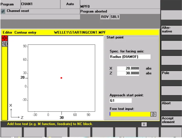
The input field with the input focus is indicated by the yellow background color. Once the input is acknowledged with "Accept element" or "Abort", you can navigate around the contour chain using the \uparrow \downarrow arrow keys. The current position in the chain is indicated in red.
Select the "Accept element" softkey to store the starting point. You can add the next element by selecting the appropriate softkey:
The approach motion to the starting point can be changed from G0 (rapid traverse) to G1 (linear interpolation) via the "Approach starting point" field. You can define a specific feedrate for G1 via the "Free text input" field,
e.g. G1 F0.3.
6 "Program" operating area 01/2008 6
6.7 Free contour programming
Alternative Position the cursor on the "Transverse axis dimension" field and click on the field using the "Alternative" softkey (or with the "Selection" key) repeatedly until the dimension you require is displayed.
1 0 ... Enter the values for the starting point.
Accept element The values you have entered are accepted when you select "Accept element" and you can then add the next element by selecting the appropriate softkey.
Sequence of operations
Define contour elements From the starting point enter the first contour element, e.g., straight line. Enter all of the data from the workpiece drawing: Length of straight lines, end position, transition to following element, angle of pitch, etc.
All parameters Select the "All parameters" softkey to display a selection list of all the parameters for the contour element.
If you leave any parameter input fields blank, the control assumes that you do not know the right values and attempts to calculate these from the settings of the other parameters.
The contour is always machined in the programmed direction.
 You can select an existing contour element with "INPUT". A new contour element is inserted after the cursor when you select one of the contour elements on the horizontal softkey bar; the input focus is then switched to the parameter input on the right of the graphic display.
You can navigate around the contour chain again after selecting "Accept element" or "Abort". The following contour elements (example for turning: G18) are available for the definition of contours.
Horizontal line Straight line in the horizontal direction. Enter the end point of the straight line (incremental/absolute can be selected with the "Alternative" softkey), program the transition to the following element and then press the "Accept element" softkey.
Vertical line Straight line in the X direction.
Str. line any directio Oblique line in the X/Z direction. Enter the end point of the line using coordinates or an angle.
Circle Arc with any direction of rotation
©Siemens AG 2008 All rights reserved.
6
"Program" operating area
6.7 Free contour programming
6
Sequence of operations
Contour transition elements A transition element can be used whenever there is a point of intersection between two neighboring elements; this can be calculated from the input values.
You can choose to insert either a radius RD or a chamfer FS as the transition element between any two contour elements. The transition is always appended to the end of a contour element. You select transition elements in the parameter input screen for the relevant contour element.
The undercut transition element is only offered in turning technology, see Chapter "Undercuts in turning technology".
Abort When you select "Abort", the contour element values are discarded and you return to the main screen. The input focus switches back to the contour chain.
Delete value The values for the element are deleted.
Radius or chamfer at the start or end of a turning contour.
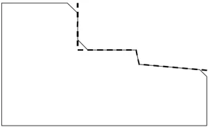
In simple turning contours a chamfer or radius should generally be appended at the start and end of the contour.
These form a closure to the axially parallel blank:

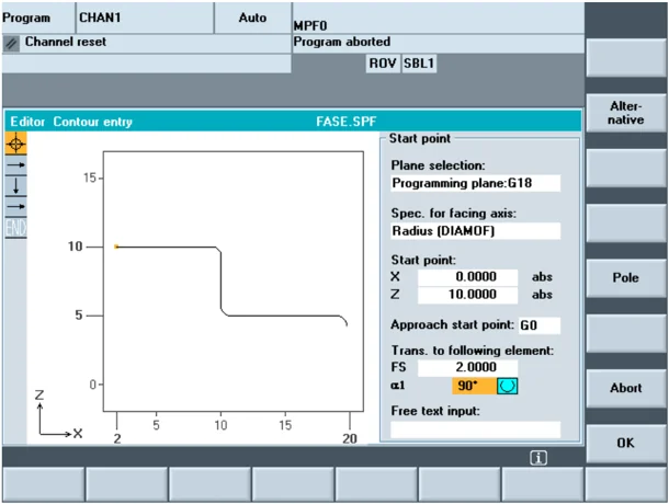
You select the direction of transition for the contour start in the starting point screen. You can choose between chamfer and radius. The value is defined in the same manner as for the transition elements.
In addition, four directions can be selected in a single selection field. You select the direction of the transition element for the contour end in the end screen. This selection is always listed, also if no transition was entered in the preceding elements.
6 "Program" operating area 01/2008 6
6.7 Free contour programming
Example
The selected transition chamfer on the contour start and its given value is displayed for clarity in an output field in the end screen next to the direction selection:
Symbolic representation of contour elements
The elements of the contour and pole, if applicable, are displayed next to the graphic window using symbols in the sequence in which they were programmed in a contour chain.
Parameter with gray background:
These parameters have been calculated by the control and cannot be altered.
When the programmable parameter input fields (white background) are altered, the control calculates new data, which are then immediately displayed in the input screen.
I nput value is already calculated
With some contours, the control may already have calculated an input value from other settings.
Problems may then arise if the control-calculated value does not tally with the workshop drawing. In this case, you must delete the settings from which the control has automatically calculated the input value. You can then enter the precise value from the workshop drawing.
©Siemens AG 2008 All rights reserved.
6
6.7 Free contour programming
"Program" operating area
6
Free text input
Under "Free text input" you can enter a comment that is inserted in the program at the end of the contour (e.g.,, specifying the technology, feedrate, M function).
Contour allowance
By selecting "Contour allowance", you can specify the allowance parallel to the contour and the side of the contour on which the allowance applies. It is displayed as an allowance in the graphics window.
It is possible to change the allowance and the parameters from the original contour. These changes are applied to subsequent machining operations in the part program, e.g., for grinding.
6.7.2 Undercuts for turning technology

Limitations
Function
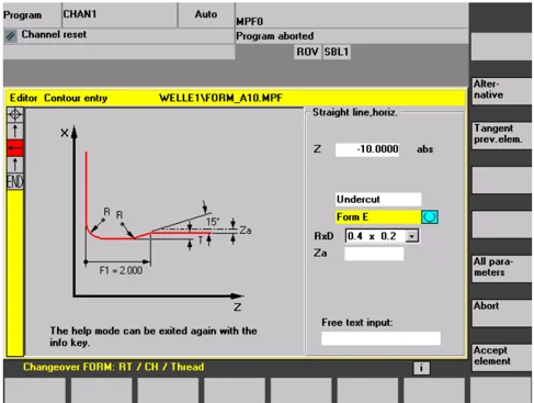
The form E and F undercut and form DIN 76 and general thread undercut functions are only activated when turning technology is enabled.
The display machine data 9020: TECHNOLOGY is evaluated to determine the technology.
Form E and F undercuts as well as thread undercuts are only available if level G18 is set. Undercuts are only permitted on contour edges of the rotational body, which run in the direction of the longitudinal axis (usually parallel to the Z axis). The longitudinal axis is identified by the machine data.
The machine data 20100: DIAMETER_AX_DEF for turning machines contains the name of the transverse axis (usually X). The other axis in G18 is the longitudinal axis (usually Z). If in MD 20100: DIAMETER_AX_DEF does not contain a name or contains a name that does not conform to G18, there are no undercuts.
Undercuts only appear on corners between horizontal and vertical straight lines, including any straight lines, which are at 0°, 90°, 180° or 270°. A tolerance of ±3° is required here, so that conical threads are also possible (these undercuts do not meet the standard in this case).
6 "Program" operating area
6.7 Free contour programming
01/2008 6
Operator focus When the operator focus is on "Trans. to next element", use the "Select key" or "Alternative" softkey to select Undercut.
When the focus is on the following field, the undercut form can be defined. The "Select key" or the "Alternative" softkey can be used to select the following options:
- Form E
- Form F
- DIN 76 thread
- Thread general
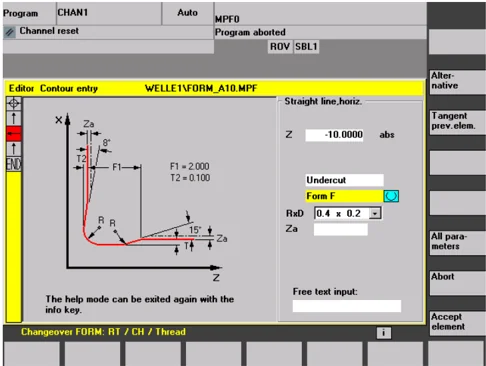
Operation If the undercut form is specified, the RxT field can be opened with the input key and the desired coordinates can be selected with the cursor keys. The desired coordinates can also be selected by repeatedly pressing the "Select key".
If the diameter is already known when selecting the undercut, the list box displays a suggested value.
Za is the machining allowance (grinding allowance) permitted according to DIN 509.
Form E

Form F
©Siemens AG 2008 All rights reserved.
6
6.7 Free contour programming
"Program" operating area
DIN thread
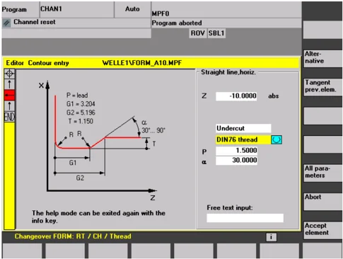
In the case of standard thread undercuts, the characteristic size of the thread pitch is P. The depth, length and transition radius of the undercut are calculated according to the DIN standard. The (metric) thread pitches specified in DIN 76 can be used. The arc-in angle can be freely selected in the 30°-90° range. If the diameter is known when selecting the undercut, an appropriate thread pitch is suggested. Forms DIN 76 A (external control) and DIN 76 C (internal control) are available. The program detects the two forms automatically using their geometry and topology.
Thread general
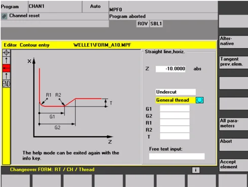
Based on the thread undercut according to DIN (see above) you can use the "General thread" undercut type to create specific undercuts, e.g., for inch threads. The following inputs can be made:
6 "Program" operating area
6.7 Free contour programming
6.7.3 Parameterizing contour elements
Function
In principle, input screens are handled according to the same procedure already described for handling contour elements STRAIGHT LINE, OBLIQUE LINE and CIRCLE.
To help you to program a contour, the following softkeys are also available:
Tangent to preceding element
The "Tangent preced. elem." softkey presets the angle \alpha2 to a value of 0. The contour element has a tangential transition to the preceding element, i.e. the angle to the preceding element (\alpha2) is set to 0 degrees.
Display additional parameters
If your drawing contains further data (dimensions) for a contour element, select the "All parameters" softkey to extend the range of input options for the element.
The "Alternative" softkey is displayed only in cases where the cursor is positioned on an input field with several switchover settings.
Select dialog
Some parameter configurations can produce several different contour characteristics. In such cases, you will be asked to select a dialog. By clicking the "Select dialog" softkey, you can display the available selection options in the graphic display area.
Select the "Select dialog" softkey to make the correct selection (black solid line) and confirm your choice with the "Accept dialog" softkey.
Changing a selected dialog
If you want to change an existing dialog selection, you must select the contour element in which the dialog was originally chosen. Both alternatives are displayed again when you select the "Change selection" softkey.
You can select another dialog.
Clear a parameter input field
You can delete the value in the selected parameter input field with the DEL key or "Delete value" softkey.
©Siemens AG 2008 All rights reserved.


6
6.7 Free contour programming
"Program" operating area 6
Save a contour element
If you have entered the available data for a contour element or selected the desired contour by means of the "Select dialog" softkey, select the "Accept element" softkey to store the contour element and return to the main screen. You can then program the next contour element.
Append contour element
Use the cursor keys to select the element in front of the end marker. Use the softkeys to select the contour element of your choice and enter the values you know in the input screen for that element. Confirm your inputs with the "Accept element" softkey.
Select contour element
 Position the cursor on the desired contour element in the contour chain, and select using the "Input" key. The parameters for the selected element will then be displayed. The name of the element appears at the top of the parameterization window.
If the contour element can be represented geometrically, it is highlighted accordingly in the graphic display area, i.e. the color of the contour element changes from black to red.
Modifying contour element
 You can use the cursor keys to select a programmed contour element in the contour chain. The "Input" key displays the parameter input fields. These can now be edited.
Insert a contour element . Use the cursor keys to select the contour element after which you wish to insert another element in the contour chain. Then select the contour element to be inserted from the softkey bar.
After you have configured the parameters for the new contour element, confirm the insert operation by selecting the "Accept element" softkey. Depending on the new status of the contour, the contour elements below are updated automatically or when the cursor arrow is hovered over them. Contour elements that appear after the insertion point and are not updated are displayed in green in the contour chain.
Delete contour element
Use the arrow keys to select the element you wish to delete. The selected contour symbol and associated contour element in the programming graphic are highlighted in red. Then press the "Delete element" softkey and confirm the query.
Undo an input
By selecting the "Abort" softkey you can return to the main screen, without transferring the last edited values to the system.
6 "Program" operating area 01/2008 6
6.7 Free contour programming
6.7.4 Graphically displaying the contour
Function
The graphics window displays the progress of the contour chain as you configure the parameters for the contour elements. The element you have selected is displayed in red in the graphics window. Navigation within the contour is described in "Program contour".
The created contour element can be displayed in various line types and colors depending on its status:
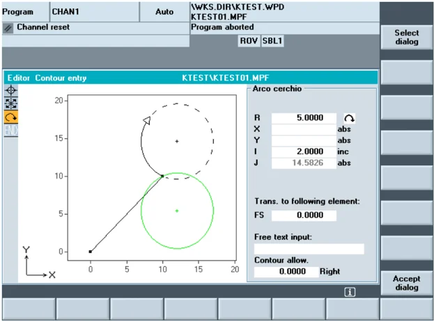
The contour is displayed to the extent it can be interpreted by the control on the basis of parameter inputs. If the contour is still not displayed in the programming graphic, further values must be entered. Check the contour elements you have already programmed, if required. You may have forgotten to enter all of the known data. The coordinate system scaling is automatically adapted to changes in the complete contour.
6
"Program" operating area 6.7 Free contour programming 6
The position of the coordinate system is displayed in the graphics window.
Contour allowance Here, you enter the complete description of the allowance parallel to the contour and the side of the contour on which the allowance applies.
6.7.5 Symmetrical contours with milling technology
Function Milling contours are often symmetrical. To exploit the symmetry of contours only the relevant parts of the contour are input, the remainder is created through replication.
Symmetries Closed symmetrical contours can be created through a combination of mirroring and turning repetitions:
-
Mirroring: The programmed contour can be mirrored in the starting or end point on any given straight line. In addition, a radius or chamfer can be entered in the mirroring point.
-
Repetition for closed contour: The mirrored contour can be closed to the left or to the right through repetition. In addition, a radius or chamfer can be input at the repetition corner points (similar to closing a contour from the end point to the starting point).
Example

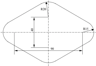
6 "Program" operating area 6.7 Free contour programming 01/2008 6
The relevant (non-symmetrical) part of the contour is described as standard:
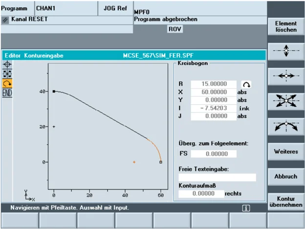
The finished contour is created through mirroring and repetition:
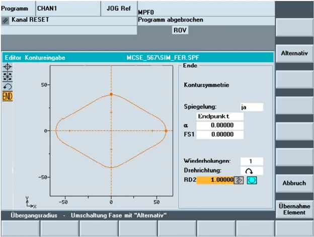
The lines of symmetry are displayed using a dashed line. The mid point of the created contour is marked with a cross. The symmetry is only visible on the end point.
©Siemens AG 2008 All rights reserved.
6 01/2008 "Program" operating area 6.7 Free contour programming 6
i Broken-line graphics In broken-line graphics, the contour is displayed with starting and end points. The cloned elements are marked without starting and end points. In addition, the lines of symmetry are displayed with dashed lines. In program overview, the entire contour is displayed without starting and end points and without lines of symmetry.
Chamfers and rounding When mirroring, the contour is reflected in the starting or end point. A chamfer or rounding can be added at this stage.
During repetition, the open contour is cloned to create a closed contour. The number N shows how many parts are required to create the closed contour. A chamfer or rounding can be added between these parts. The direction of rotation for closing can be freely selected.
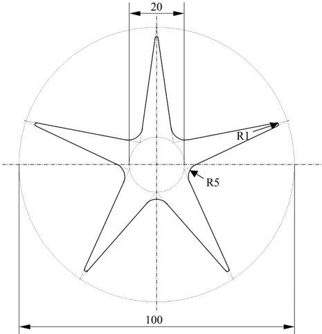
Example
Behavior of chamfers and rounding

Maximum contour size The maximum number of contour elements is limited to 250. Contour * Mirroring (1 or 2) * Repetition (N) ≤ 250 Elements
6 "Program" operating area 01/2008 6
6.7 Free contour programming
6.7.6 Specifying contour elements in polar coordinates, closing the contour
Function
The description given above of defining the coordinates of contour elements applies to the specification of positional data in the Cartesian coordinate system. Alternatively, you have the option to define positions using polar coordinates.
When programming contour definitions, you can define a pole at any time prior to using polar coordinates for the first time. Programmed polar coordinates subsequently refer to this pole. The pole is modal and can be re-defined at any time. It is always entered in absolute Cartesian coordinates. The contour calculator converts values entered as polar coordinates into Cartesian coordinates. Programming in polar coordinates is only available after entering a pole. The pole input does not generate a code for the NC program.
Pole
The polar coordinates are valid in the level selected with G17 to G19.
The pole is a contour element that can be edited, which itself does not contribute to the contour. It can be entered when the starting point of the contour is defined or anywhere within the contour. The pole cannot be created before the starting point of the contour.
Enter polar coordinates
Polar coordinates
More
The "More" softkey in the basic plane of the contour programming accesses the "Pole" subscreen and the "Close contour" softkey.
Pole
The pole can only be entered in absolute Cartesian coordinates. The "Pole" softkey is also present in the starting point screen. This enables the pole to be entered at the start of a contour, so that the first contour element can be entered in polar coordinates.
Close contour
The contour is closed by a straight line between the last entered contour point and the starting point.
©Siemens AG 2008 All rights reserved.
6 01/2008 "Program" operating area 6.7 Free contour programming 6
Additional information
If the straight line that was generated with close contour is linked to the start element of the contour with a radius or chamfer, the radius or chamfer must be specified explicitly as follows:
- Close contour, input key, enter radius/chamfer, accept element. The result then corresponds exactly to what would occur if the closing element were to be entered with the radius or chamfer.
- Close contour can only be used for entering contour elements in polar coordinates if the starting point of the contour was set to polar and the same pole is still valid at the closing point.
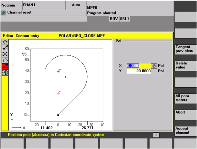
Input switchover: Cartesian/polar
Once a pole has been set – whether inserted at the starting point or subsequently – the contour elements can be entered as:
- Circular arcs
- Straight lines/(inclined) or as polar coordinates. To switch between Cartesian and polar coordinates additional toggle fields are displayed for "Straight line, any" and "Circular arc" in both the basic contour input view and the view with "All parameters". A toggle field is not displayed if no poles exist. Input fields and display fields are then only available for Cartesian values.
Absolute/incremental input Absolute and incremental polar coordinates can be input for "polar". The input fields and display fields are labeled inc and abs.
Absolute polar coordinates are defined by an absolute distance to the pole that is always positive and an angle in the range of 0° ... +/- 360°. When absolute dimensions are specified, the angular reference is based on a horizontal axis of the working plane, e.g., X axis with G17.
6 "Program" operating area
6.7 Free contour programming
The positive direction of rotation runs counter-clockwise. If there are several input poles, the definitive pole is the last pole before the input or edited element.
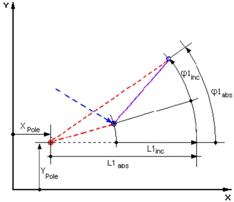
Incremental polar coordinates relate to both the definitive pole and the end point of the preceding element.
For an incremental input, the absolute distance to the pole is calculated using the absolute distance from the end point for the preceding element to the pole plus the length increment that was entered. The increment can be positive or negative.
The absolute angle is calculated accordingly using the absolute polar angle of the preceding element plus the angular increment. Here it is not necessary for the preceding element to have been entered as polar.
In contour programming, the contour calculator converts the Cartesian coordinates of the preceding end point using the definitive pole into polar coordinates. This also applies if the preceding element has been given in polar coordinates, since this could relate to another pole if a pole has been inserted in the meantime.